manuals.online logo
Brands
  1. Home
  2. •
  3. Brands
  4. •
  5. Turner Designs
  6. •
  7. Measuring Instrument
  8. •
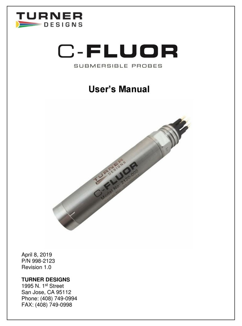
  9. Turner Designs C-FLUOR User manual

Turner Designs C-FLUOR User manual

www.turnerdesigns.com
998-2132
Revision A
Page 1 of 3
Digital C-FLUOR Quick Start Guide
“A”= PTSA“A”= PTSA
C
“C” = Chlorophyll
“A”= PTSA“A”= PTSA
C
“C” = Chlorophyll
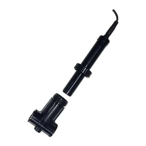
Congratulations on the purchase of your new Digital C-FLUOR Submersible Probe. We are committed to customer
satisfaction. If you need assistance, technical specialists are available to answer your questions at 408-749-0994 or
toll-free at 877-316-8049. This Quick Start Guide will help you set up your Digital C-FLUOR Submersible Probe and
describe how to take measurements so you can start collecting data as quickly as possible.
Your Digital C-FLUOR Probe is configured for the application that correlates with the identification letter stamped on
the 6-pin bulkhead connector (see list below). For Digital C-FLUOR Probes that do not have a connector, the
identification letter will be etched on the body next to the part number.
“C” = Chlorophyll “R” = Rhodamine WT
“F” = Fluorescein “P” = Phycocyanin
“E” = Phycoerythrin “U” = CDOM / fDOM
“O” = Crude Oil “B” = Optical Brighteners
“T” = Turbidity “D” = Red Excitation
Initial Connections
Note: Supply voltages greater than 15 VDC will damage the probe.
Use the wiring guide below to connect the Digital C-FLUOR to your data logger or third-party system.
NOTE: If you purchased the Programming Kit P/N 2120-900 and prefer to use software to set
up the Digital C-FLUOR, see Section 
Use the communication protocol below to set up communication with your DigitalC-FLUOR.
Baud Rate: 9600 (default)
NOTE: If the baud rate was manually changed, please use the manually set baud rate for
communication.
Data bits: 8
Parity: None
Stop bits: 1
Flow Control: None
After configuring the communication settings, supply power to the instrument and see Section .
C-FLUOR
Pins/Wires Pin
Number Function Connection
Red 1 Supply Voltage
3 –15 VDC PSU –Positive Connection
Black 2 Supply Ground, 0VDC PSU –Ground Connection
Orange 3 Receive Data RX
Green 4 Transmit Data TX
Blue 5 Digital Ground GND
Yellow 6 N/A -
www.turnerdesigns.com
998-2132
Revision A
Page 2 of 3
Digital C-FLUOR Quick Start Guide
Using Commands to Communicate with the Digital C-FLUOR
With the C-FLUOR connected and powered make the following functional tests:
1. Is the LED on?
Hold a piece of white paper about ½ an inch in front of the optical head to ensure the LED is ON.
Note: This test does not work for Turbidity probes because they use infrared which is not visible.
2. Using the S06! command, set the Streaming Output Rate to 1 reading per second. Do you see values
being streamed at once per second rate?
3. Does the output change?
Move the light source closer to the piece of paper and check if the output value being streamed increases.
Use commands from the command list below to program and set up your Digital C-FLUOR after successfully
passing all functional tests..
Use the list below to set Streaming Output Rate
Command Name Note
I! Sensor Information For Probe Information
C! Calibration Information For Calibration Values
Bxxxx! Set Baud Rate “xxxx” refers to baud rate
(9600, 14400, 19200, 38400, 57600)
Sxx! Streaming Output Rate Puts probe into streaming mode Use table
below to determine “xx”
P! Polling Mode Puts probe into polling mode
R! Read Command Only when in Polling mode
M! Report the Current Mode Returns S with rate or P
xx Readings per second Seconds between
readings
01 Not Available
02 16
03 8
04 4
05 2
06 1 1 (factory default)
07 2
08 5
09 10
10 15
11 30
12 60
13 120
14 300
15 600
16 1800
17 3600
www.turnerdesigns.com
998-2132
Revision A
Page 3 of 3
Digital C-FLUOR Quick Start Guide
Using Software to Communicate with the Digital C-FLUOR
With the C-FLUOR connected to your computer and power supply, and communicating with the software,
answer questions 1-3 to perform the following functional tests:
1. The LED is on?
Hold a piece of white paper about ½ an inch in front of the optical head to ensure the LED is ON.
Note: This test does not work for Turbidity probes because they use infrared which is not visible.
2. Is there output?
Click the “Get Datapoint” button; if a value is displayed in the box then the instrument’s output is working.
3. Does the output change?
Move the light source closer to the piece of paper and again click the “Get Datapoint” button; if the output
increases then the instrument’s detector is working.
If the instrument passed all functional tests, begin configuring your Digital C-FLUOR Probe using the software.
To program the Digital C-FLUOR Probe using software, connect the probe to your computer using the Digital C-
FLUOR RS-232 Programming Cable P/N 2120-160 and connect the 12 volt power supply P/N 7000-941 to the
Programming Cable’s power jack, then follow the instructions below:
1. Once USB drivers have automatically installed, download and install Digital C-FLUOR’s Software from
www.turnerdesigns.com.
2. After software has successfully installed, double-click the software’s icon which should have been
automatically added to your desktop.
3. Click “Communicate With C-FLUOR” and wait a few minutes for the software to detect the connected
probe.
4. When connected, C-FLUOR Communication Status radio button will change from red to green
12V Power Supply12V Power Supply
RS-232 ProgrammingCable

Other manuals for C-FLUOR

2

Other Turner Designs Measuring Instrument manuals
Turner Designs 10-AU Use and care manual

Turner Designs

Turner Designs 10-AU Use and care manual

Turner Designs 8000 Manual

Turner Designs

Turner Designs 8000 Manual

Turner Designs C-FLUOR User manual

Turner Designs

Turner Designs C-FLUOR User manual

Turner Designs Little Dipper 2 User manual

Turner Designs

Turner Designs Little Dipper 2 User manual

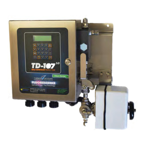
Turner Designs TD-107 5.0 User manual

Turner Designs

Turner Designs TD-107 5.0 User manual

Turner Designs Opti-Trace User manual

Turner Designs

Turner Designs Opti-Trace User manual

Turner Designs Ballast-Check 2 User manual

Turner Designs

Turner Designs Ballast-Check 2 User manual

Turner Designs TD-5100 ECA User manual

Turner Designs

Turner Designs TD-5100 ECA User manual

Turner Designs FluoroSense User manual

Turner Designs

Turner Designs FluoroSense User manual

Turner Designs Trilogy User manual

Turner Designs

Turner Designs Trilogy User manual

Turner Designs Ballast-Check 2 User manual

Turner Designs

Turner Designs Ballast-Check 2 User manual

Turner Designs 10-AU User manual

Turner Designs

Turner Designs 10-AU User manual

Turner Designs Enviro-T User manual

Turner Designs

Turner Designs Enviro-T User manual

Turner Designs C3 User manual

Turner Designs

Turner Designs C3 User manual

Turner Designs AquaFlash User manual

Turner Designs

Turner Designs AquaFlash User manual

Turner Designs AquaFluor User manual

Turner Designs

Turner Designs AquaFluor User manual

Turner Designs Ballast-Check 2 User manual

Turner Designs

Turner Designs Ballast-Check 2 User manual

Turner Designs C3 User manual

Turner Designs

Turner Designs C3 User manual

Turner Designs AquaFlash User manual

Turner Designs

Turner Designs AquaFlash User manual

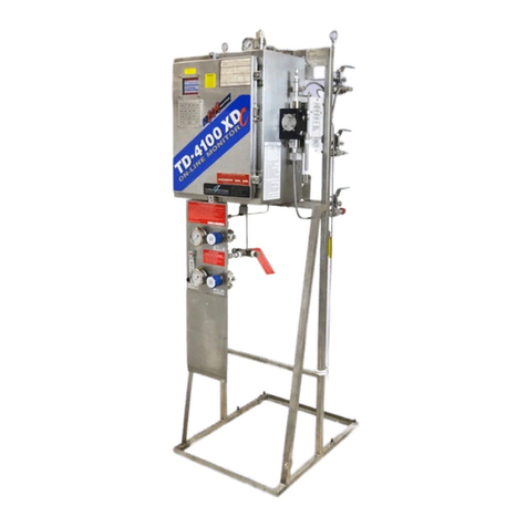
Turner Designs TD-4100XD E09 Installation and operating instructions

Turner Designs

Turner Designs TD-4100XD E09 Installation and operating instructions

Turner Designs Little Dipper User manual
Turner Designs

Turner Designs Little Dipper User manual

Turner Designs FluoroSense User manual

Turner Designs

Turner Designs FluoroSense User manual

Turner Designs Ballast-Check 2 User manual

Turner Designs

Turner Designs Ballast-Check 2 User manual

Turner Designs 10-AU Guide

Turner Designs

Turner Designs 10-AU Guide

Popular Measuring Instrument manuals by other brands

VOLTCRAFT UV-500 operating instructions

VOLTCRAFT

VOLTCRAFT UV-500 operating instructions

Reed Instruments R4700SD instruction manual

Reed Instruments

Reed Instruments R4700SD instruction manual

ETG ETG6900 User instruction manual

ETG

ETG ETG6900 User instruction manual

Cargo Data Boomerang 2 use instructions

Cargo Data

Cargo Data Boomerang 2 use instructions

dallmeier DMX 800 Smartix Configuration

dallmeier

dallmeier DMX 800 Smartix Configuration

Endress+Hauser Liquiline CA80FE Brief operating instructions

Endress+Hauser

Endress+Hauser Liquiline CA80FE Brief operating instructions

Etatron AG-Select B2 MENU

Etatron

Etatron AG-Select B2 MENU

DR. LANGE CADAS 100 LPG 185 Programming instructions

DR. LANGE

DR. LANGE CADAS 100 LPG 185 Programming instructions

Huato S380WS Series user manual

Huato

Huato S380WS Series user manual

ATAGO 4430 instruction manual

ATAGO

ATAGO 4430 instruction manual

Force 45371 quick start guide

Force

Force 45371 quick start guide

Aquaread LeveLine Series instruction manual

Aquaread

Aquaread LeveLine Series instruction manual

Horizon Educational DA-100 instruction manual

Horizon Educational

Horizon Educational DA-100 instruction manual

Rover Instruments MASTER STC user manual

Rover Instruments

Rover Instruments MASTER STC user manual

Sequoia LISST-100X user manual

Sequoia

Sequoia LISST-100X user manual

Huazheng HZX52AA manual

Huazheng

Huazheng HZX52AA manual

PreSens pH-10 mini instruction manual

PreSens

PreSens pH-10 mini instruction manual

Rayto RT-7600S user manual

Rayto

Rayto RT-7600S user manual

manuals.online logo
manuals.online logoBrands
  • About & Mission
  • Contact us
  • Privacy Policy
  • Terms and Conditions

Copyright 2025 Manuals.Online. All Rights Reserved.