HG E2000 User manual

User Manual HG E2000 HIGH TIP
HG Machines ApS hg-machines.com hello@hg-machines.com
Page 1
User manual
HG E2000 HIGH TIP

User Manual HG E2000 HIGH TIP
HG Machines ApS hg-machines.com hello@hg-machines.com
Page 2
Table of contents
1. Introduction............................................................................................................ 5
2. Definitions .............................................................................................................. 6
2.1 Abbreviations..................................................................................................... 6
2.2 Terms, concepts, and designations ....................................................................... 6
2.3 Icons/pictograms in this user manual.................................................................... 6
3. Signs/marks found on the machine............................................................................ 6
3.1 CE label/machine-type plate ................................................................................ 6
3.2 Safety signs....................................................................................................... 7
3.3 Other signs........................................................................................................ 8
4. Machine description ................................................................................................. 8
4.1 General machine design ...................................................................................... 9
4.1.1 Dimensional sketch ....................................................................................... 9
4.1.2 Main parts ................................................................................................. 11
4.1.3 Main components........................................................................................ 11
4.2 EU Declaration of Conformity ............................................................................. 13
4.3 Description of functionalities .............................................................................. 15
4.4 Technical specifications ..................................................................................... 16
4.6 Warranty......................................................................................................... 18
4.7 Machine use .................................................................................................... 19
4.7.1 User requirements and restrictions................................................................ 19
4.7.2 Intended use.............................................................................................. 19
4.7.3 Unintended use .......................................................................................... 19
4.8 Supplied equipment .......................................................................................... 20
5. 5. Residual hazard................................................................................................. 21
6. Transport, use, and operation of the machine ........................................................... 24
6.1 Machine transport/towing .................................................................................. 24
6.1.1 Transport................................................................................................... 24
6.1.2 Towing ...................................................................................................... 26
6.2 Operating space ............................................................................................... 26
6.3 Emergency stop –Use and location on the machine.............................................. 28
6.3.1 Scope of emergency stop............................................................................. 29
6.4 Information during operation ............................................................................. 29
6.4.1 Visual information/warnings ......................................................................... 29
6.4.2 Acoustic warnings ....................................................................................... 30

User Manual HG E2000 HIGH TIP
HG Machines ApS hg-machines.com hello@hg-machines.com
Page 3
6.5 Normal use...................................................................................................... 30
6.5.1 Electrical supply (supply separator)............................................................... 30
6.5.2 Filling up the container ................................................................................ 30
6.5.3 How to operate the machines functions ......................................................... 31
6.5.4 Unloading the container............................................................................... 35
6.5.5 Charging.................................................................................................... 46
6.5.6 Preparing for use ........................................................................................ 48
6.5.7 Tire pressure and maintenance..................................................................... 49
6.5.8 Driving ...................................................................................................... 49
6.6 Cleaning.......................................................................................................... 54
6.6.1 Safety steps while cleaning .......................................................................... 54
6.7 Safety while operating ...................................................................................... 54
6.7.1 Built-in functionality limitations .................................................................... 54
6.7.2 Other safety notes ...................................................................................... 55
6.7.3 Start-up after a regular stop ........................................................................ 56
6.7.4 Starting up after an emergency stop ............................................................. 56
6.7.5 Start-up after service/repair......................................................................... 57
6.7.6 Freeing a person in the event of an overrun or jam ......................................... 57
6.8 Troubleshooting/FAQ ........................................................................................ 57
7. Service, repair, and maintenance ............................................................................ 59
7.1 General ........................................................................................................... 59
7.1.1 Maintenance............................................................................................... 59
7.1.2 Spare parts ................................................................................................ 60
7.1.3 Safety during repair/maintenance ................................................................. 61
7.1.4 Disposal of replaced parts ............................................................................ 61
7.2 Lubricating moving parts and filling with hydraulic oil ........................................... 61
7.2.1 Lubrication of moving parts.......................................................................... 61
7.2.2 Filling up hydraulic oil.................................................................................. 62
7.2.3 Security regarding lubrication and filling ........................................................ 64
8. Storage & disposal................................................................................................. 64
8.1 Storage........................................................................................................... 64
8.2 Disposal .......................................................................................................... 67
9. Appendix.............................................................................................................. 68
9.1 Diagrams ........................................................................................................ 68
9.1.1 Electric diagram.......................................................................................... 68

User Manual HG E2000 HIGH TIP
HG Machines ApS hg-machines.com hello@hg-machines.com
Page 4
9.1.2 Hydraulic diagram....................................................................................... 69
9.2 Blueprints........................................................................................................ 69
9.2.1 Overview prints .......................................................................................... 69
9.2.2 Parts prints ................................................................................................ 69
9.3 Additional manuals ........................................................................................... 69
9.4 Third-party documentation ................................................................................ 69
9.5 Checklist for HG Machines HG E2000 and HG E2000 High Tip................................. 70

User Manual HG E2000 HIGH TIP
HG Machines ApS hg-machines.com hello@hg-machines.com
Page 5
1. Introduction
The 100% electric 2-ton dumper runs for an entire workday –it is easy and quick to charge.
The E2000 can carry up to 2 tons, while the lithium battery allows it to run for 12 hours –more than a full
working day. This makes it simple to use without worrying about emptying the battery. As a matter of fact, it
charges from 20-80% in just 2.5 hours.
It is made for urban construction sites for landscapers, contractors, demolition companies, and rental
companies.
HG E2000 is designed in Denmark and built at our factory.
•12 hours of effective driving time –more than enough for a full working day
•Fast charging –20 to 80% battery in 2 hours, 0-100% in 3.
•Charges with a simple car charger, 16A power, or 220v EU plug
•Lithium battery technology –LiFePO4
•Drive with one pedal for maximum comfort
•Significantly reduces noise levels
•Emission-free work environment
Fabrikant:
HG Poland Sp. Z. O. O. HG Machines ApS
+48 91 885 23 04 +45 75 89 12 44
Prosta 34 hello@hg-machines.com
72-100 Łozienica www.hg-machines.com
Poland Vejlevej 15, 8722 Hedensted
CVR-nr.: PL7010040430 Denmark

User Manual HG E2000 HIGH TIP
HG Machines ApS hg-machines.com hello@hg-machines.com
Page 6
2. Definitions
2.1 Abbreviations
Table 1: Abbreviations
Abbreviation
Terms
Explanation
OADC
On-Air Data Communication
Device to get live updates from the machine
(optional equipment).
EM break
Electromagnetic brake reduction
Built-in brake functionality
2.2 Terms, concepts, and designations
Table 2: Expressions
Terms
Explanation
Intended use
The function(s) the machine is designed and manufactured to perform.
Unintended use
Description of the improper and illegal use of the machine that can reasonably be
expected to occur.
Residual hazard
A hazard that cannot be eliminated through its own safe construction or functional
safety.
2.3 Icons/pictograms in this user manual
Table 3: Icons
Icon
Meaning
Explanation
General information
Information that should be read before using the
machine.
Safety regulation
Safety regulation that informs the operator to orient
himself when operating the machine.
3. Signs/marks found on the machine
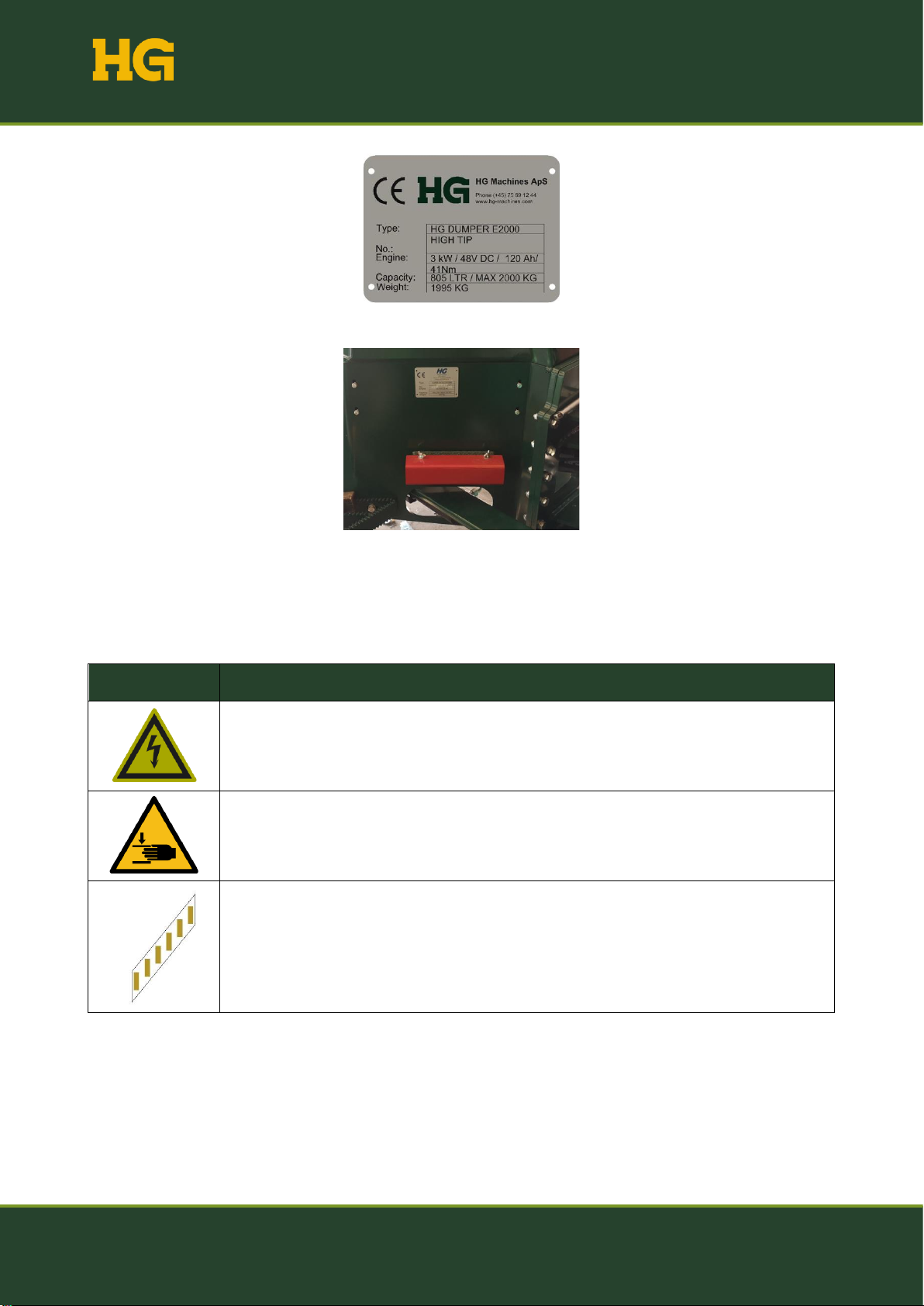
3.1 CE label/machine-type plate
The CE marking plate is on the machine's left side behind the swivel joint (see Figure 1). The nameplate must
not be removed or replaced if it is missing or is so damaged that it has become unreadable (see Figure 2).
User Manual HG E2000 HIGH TIP
HG Machines ApS hg-machines.com hello@hg-machines.com
Page 7
Figure 1: CE marking plate
Figure 2: Placement of CE marking plate
3.2 Safety signs
Safety-related labels and symbols attached to the machine and their mean.
Pictogram
Definition
Warning: Electrical voltage
Warning: Hand-crushing
Warning mark for swivel arms
User Manual HG E2000 HIGH TIP
HG Machines ApS hg-machines.com hello@hg-machines.com
Page 8
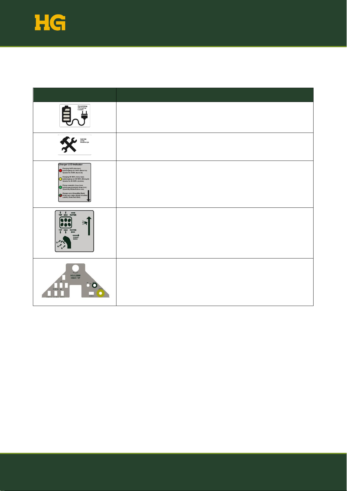
3.3 Other signs
The labels and signs attached to the machine and what they mean.
Pictogram
Definition
It shows where the charger is located on the machine.
Shows where tools can be stored on the machine.
Overview with meaning and explanation of battery diode color.
Overview of joystick functionalities.
Dashboard
4. Machine description
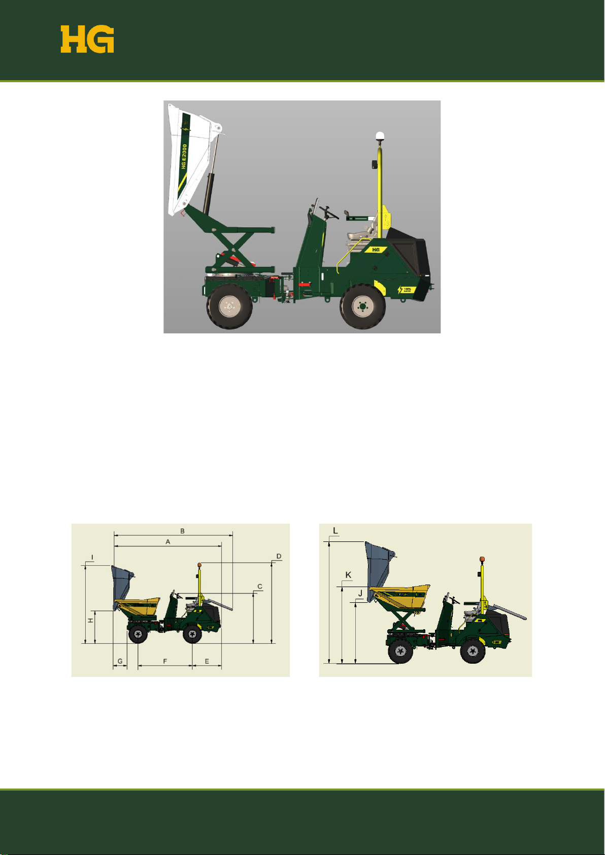
The HG E2000 High Tip is an emission-free dumper used to transport and load/unload various materials (see
Figure 3). It is a machine for professionals on, for example, construction sites, but it is also approved for driving
on public roads.
User Manual HG E2000 HIGH TIP
HG Machines ApS hg-machines.com hello@hg-machines.com
Page 9
Figure 3: HG E2000 High Tip
The central part of the HG E2000 is a hydraulically driven container that can be rotated and tipped. For this,
the machine has hydraulically operated swivel arms that allow the container to be raised and lowered. The
machine is equipped with a swivel joint that connects the front and rear, making the machine maneuverable.
Each wheel is driven by an electric motor with built-in brake functionality (EM brake). This construction gives
the machine four-wheel drive.
4.1 General machine design
4.1.1 Dimensional sketch

User Manual HG E2000 HIGH TIP
HG Machines ApS hg-machines.com hello@hg-machines.com
Page 10
Figure 4: Machine measurement
Symbol
(mm)
Symbol
(mm)
A
3975
K
2145
B
4390
L
3405
C
1860
M
280
D
2989
N
1480
E
1082
O
764
F
2010
P
452
G
517
Q
396
H
1205
R
1475
I
2890
S
310
J
1705
T
211

User Manual HG E2000 HIGH TIP
HG Machines ApS hg-machines.com hello@hg-machines.com
Page 11
4.1.2 Main parts
Figure 5: E2000 main parts
1: Front
2: Back
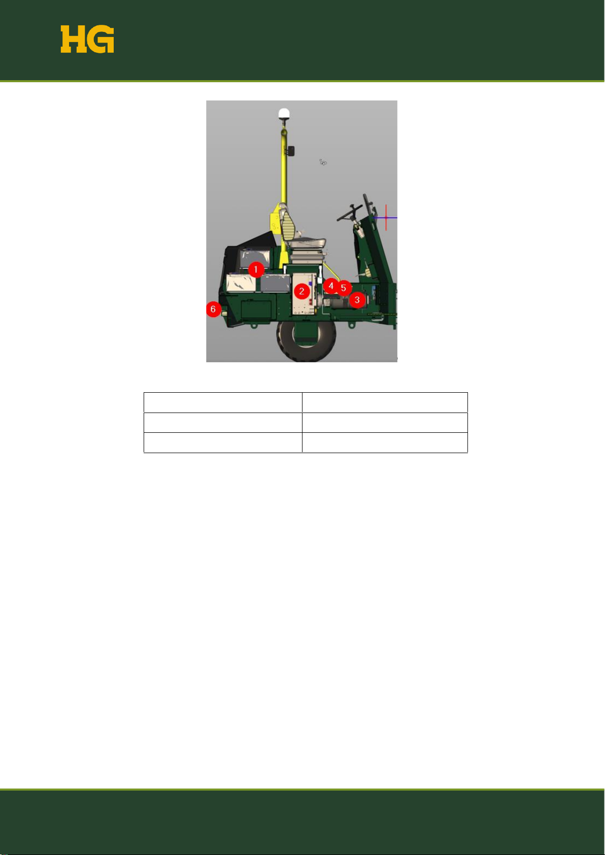
4.1.3 Main components
Figure 6: Main components - front
1: Container
2: Tip cylinder
3: Swivel arm
4: Lifting cylinder (h+v)
5: Top frame
6: Bottom frame
7: Turntable
8: Turning cylinder (h+v)
User Manual HG E2000 HIGH TIP
HG Machines ApS hg-machines.com hello@hg-machines.com
Page 12
Figure 7: Main components - back
1: Battery pack
2: Fast charger
3: Hydraulic pump and tank
4: Main controllers (left side)
5: Slave controllers (right side)
6: Tow

User Manual HG E2000 HIGH TIP
HG Machines ApS hg-machines.com hello@hg-machines.com
Page 13
4.2 EU Declaration of Conformity

User Manual HG E2000 HIGH TIP
HG Machines ApS hg-machines.com hello@hg-machines.com
Page 14
User Manual HG E2000 HIGH TIP
HG Machines ApS hg-machines.com hello@hg-machines.com
Page 15
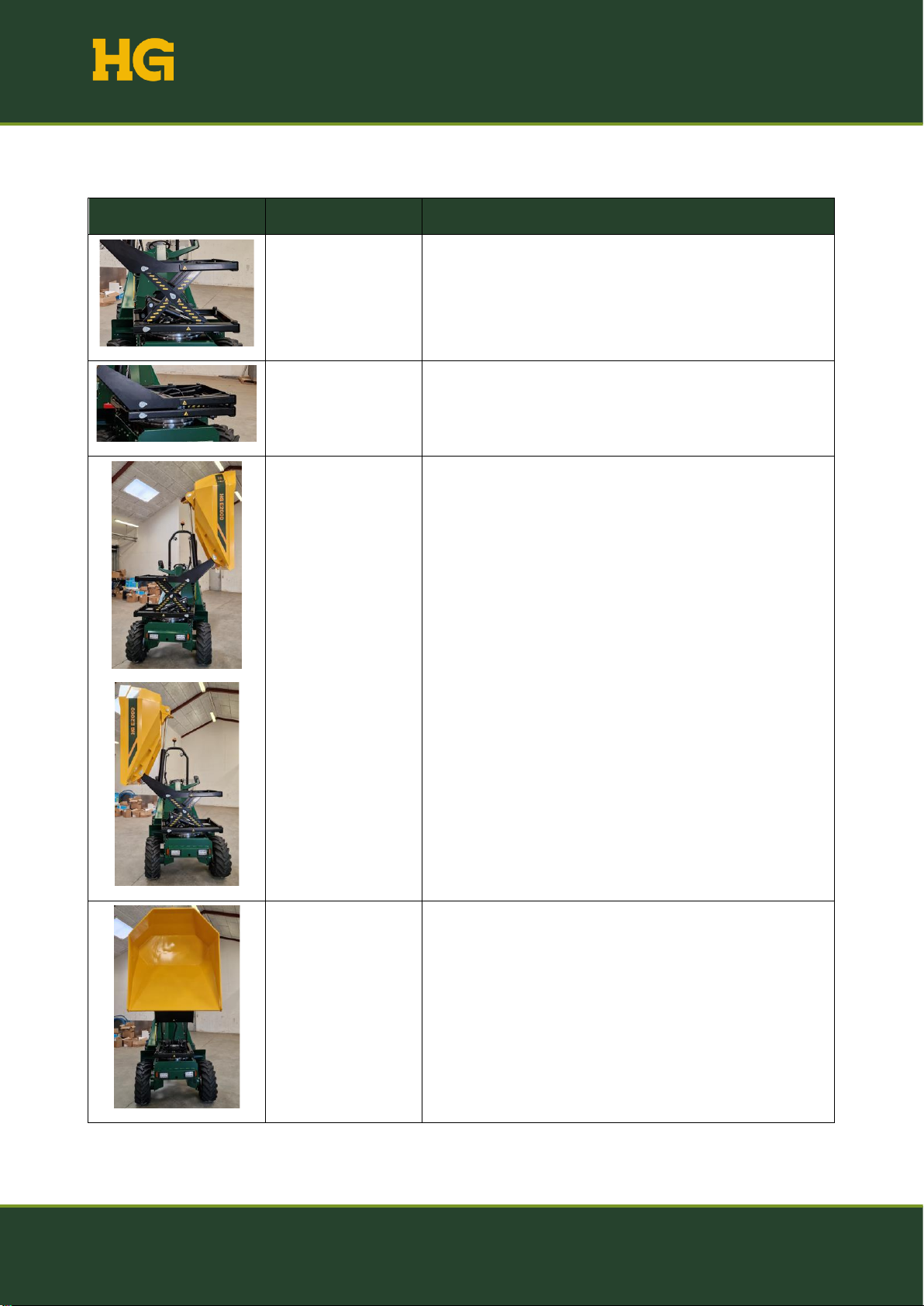
4.3 Description of functionalities
Image
Function
Description
Raising
Hydraulically driven raising function.
Lowering
Hydraulically driven lowering function.
Turning
A hydraulically driven turntable can turn the container 90
degrees to the left and right.
Tipping
A hydraulically driven tip function.

User Manual HG E2000 HIGH TIP
HG Machines ApS hg-machines.com hello@hg-machines.com
Page 16
4.4 Technical specifications
The overall technical specifications of the machine are given in Table 4.
4.5 Table 4: Technical specifications
Specifications
Width
1480 mm
Length
3979 mm
Height (Operating mode, roll
bar up)
2989 mm
Height (Transportation mode)
1910 mm
Own weight
2150 kg
Content in liters
892 L
Content in kg
2000 kg
Unloading height (Low)
1210 mm
Unloading height (High)
1715 mm
Driving speed (Hare)
0-20 km/h
Driving speed (Turtle)
0-10 km/h
Reverse speed
0-20 km/h
Battery
Lithium
360 Ah
Voltage
48V
Run time
12 hours
Temperature, charge
0°C to +55°C
Temperature, in use
-10°C to +60°C
Temperature, long-term
storage
+15°C
Protection class (IPXX)
IP 54
Charger 1 –Fast charge –160 A
Plug
CEE 5P 16A
0-100% charging time
4,1 hours
20-80% charging time
2,6 hours
Integrated charger
10000 W

User Manual HG E2000 HIGH TIP
HG Machines ApS hg-machines.com hello@hg-machines.com
Page 17
Charger 1 - Adapter type 2 car charger –160 A
Plug
CEE 5P 16A for type 2 car charger
0-100% charging time
4,1 hours
20-80% charging time
2,6 hours
Integrated charger
10000 W
Charger 2 –35A
Plug
230V plug standard EU
0-100% charging time
16 hours
20-80% charging time
10 hours
Integrated charger
1000 W
Motor
Electric
PMAC three-phase electric motor 48V
Performance
3000 W
Moment (Rated)
9,5 Nm
Moment (Peak)
19,5 Nm
Moment (Instant)
41 Nm
Pulling wheels
Dimensions
11.0/65x12/8 TL AS-504
Inches
12
Diameter
700
Width
273
Bar
4.0
Load/Kg
1400
Rim
8.50x12
Rolling circumference
2072
Other
Container function
Hydraulic tip. Tip cylinder, double-acting
High tip
Hydraulic tip. 2x Tip cylinder, double-acting
Container rotation
Hydraulic tip. 2x Tip cylinder, double-acting
Hydraulic tank
10-liter Handel 46
Sound pressure
Lpa, eq max = 81 dB(A)
Vibrations
Weighted arm/hand level max - 2.5 m/s2

User Manual HG E2000 HIGH TIP
HG Machines ApS hg-machines.com hello@hg-machines.com
Page 18
4.6 Warranty
Warranty period
HG Danmark APS provides a guarantee for 12 months. The warranty period begins on the date of delivery.
The warranty includes:
•Components that must be replaced or repaired due to material or manufacturing defects.
•The warranty does not cover wear and consumable parts such as:
oTires and hydraulic oil
The manufacturer's warranty expires if:
•The machine is misused.
•The machine is used without following the user manual and safety regulations.
•The machine is not maintained according to the instructions, or outdated spare parts are used.
•The machine is used after a fault has been detected, resulting in a more expensive repair than the
original fault.
The owner's insurance should cover:
•Fire, burglary, theft, and vandalism.
•Water and frost damage.
•Damage caused by wind and weather.
The manufacturer's warranty does not apply in such cases.
Approval of compensation claims:
The manufacturer's approval of a compensation claim requires that the defective part be shown to the
manufacturer or its representative within two weeks after the damage. Ownership of the damaged part(s) is
transferred to the supplier of the new parts.
According to the warranty, it only replaces components. It, therefore, does not cover the following:
•Shipping costs.
•Costs related to waiting time, the machine owner's working time, and travel costs.
•Operating losses and other subsequent costs.
Other
Before repair under warranty, the manufacturer must be contacted to agree on the procedure. It is too late to
claim the warranty if the repair has been initiated or completed. These warranty provisions can only be changed
through a separate agreement.

User Manual HG E2000 HIGH TIP
HG Machines ApS hg-machines.com hello@hg-machines.com
Page 19
4.7 Machine use
4.7.1 User requirements and restrictions
The operator of the HG E2000 must meet the following requirements and restrictions:
•The instructions must be read carefully. The operator must know all the machine's functions and
their correct use, as well as knowledge of controls, switches, etc.
•The operator must be at least 18 years old and have a normal state of mind and ability to use the
dumper. Please note that the legislation in the individual country may specify a different age limit for
persons who may use the dumper in given situations.
•The operator is responsible for accidents or any dangerous situations that may occur to other people
and their property.
•The operator must have adequate instructions on the use of the dumper. These instructions should
emphasize the following:
oThe importance of being careful and concentrated when working with self-propelled
machines.
oThe operator must have a good overview of the machine's surroundings - especially where
other people may be walking.
4.7.2 Intended use
The machine will be used to transport building materials and waste. The machine is operated by a seated
operator who must meet the requirements mentioned in section 4.6.1, User Requirements and Restrictions.
It is permitted to drive the machine on construction sites, areas without road surfaces, and public roads (see
section 6.5.8.1 Requirements for driving on public roads).
4.7.3 Unintended use
The machine may not be used for the following:
•It may not be operated by persons who do not know the machine's functions or are below 18 years
old.
•Do not transport with a raised container.
•Do not use it to tow other vehicles.
•Do not use it in case of insufficient ceiling height.
•Do not use in ATEX areas.
•It must not be used to lift people in the container
•It must not be used to transport people other than the operator
•May not be used for underground work (e.g., mining)
•Do not use in areas where there is insufficient lighting or daylight.
•It may not be used to transport materials weighing more than 2,000 kg.
User Manual HG E2000 HIGH TIP
HG Machines ApS hg-machines.com hello@hg-machines.com
Page 20
•Do not use it if the machine is damaged (Reduced functionality or apparent damage).
•Do not drive on uneven or steep surfaces that exceed the design limitations.
•Must not be used if all applicable regulations (cf. applicable legislation) and regulations on building
sites are not observed.
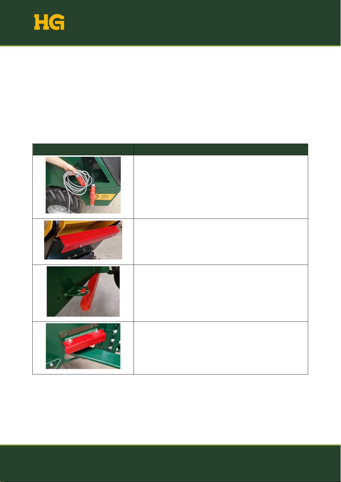
4.8 Supplied equipment
Table 5 contains an overview of the equipment delivered with the HG E2000.
Table 5: Overview of supplied equipment
Picture
Equpment
Charging cable with extension for charger (CEE type)
Safety bracket for tipping cylinder on container
Safety bracket for the swivels
Safety bracket for swivel cylinders on swivel joints (1 on each side
of the machine)
This manual suits for next models
1
Table of contents
Other HG Farm Equipment manuals


Popular Farm Equipment manuals by other brands


Pottinger
Pottinger Original inside NOVACAT 3007 T ED Operator's manual

Fransgard
Fransgard DM-3250 manual

Agria
Agria Bison 5900 Series Translation of the original operating instructions

abi
abi ARENA RASCAL PRO Setup guide

breviglieri
breviglieri b25f Series Operating and maintenance manual

Boumatic
Boumatic HD2 Rapid Exit Operator's manual


