HHV SOLAR HSTXY24xxxZ Series User manual

HHV Solar
Technologies Pvt. Ltd. No.31-
34 & 37, K ADB ndustrial Area, Phase
Ph : +91-80-
22633700; Fax : +91
Solar
Module nstallation Manual
Ref No.SIMGEN01.011113.Rev:0.
34 & 37, K ADB ndustrial Area, Phase
-1, Dabaspet, Bangalore Rural Dist-
562
22633700; Fax : +91
-80-22633811; E-mail : info@hhvsolar.com; Web:
www.hhvsolar.com
Module nstallation Manual
562
111, Karnataka, ND A.
www.hhvsolar.com
Module nstallation Manual
Solar Module Installation Manual
•
•
•
•
NEVER
STAND OR STEP
NEVER CARRY THE MODULES REST NG ON HEAD
ALWAYS MODULES SHOULD BE HANDLED BY 2 PERSONS
DO NOT CONNECT OR D
WARN NG
STAND OR STEP
ON THE MODULES
NEVER CARRY THE MODULES REST NG ON HEAD
ALWAYS MODULES SHOULD BE HANDLED BY 2 PERSONS
DO NOT CONNECT OR D
SCONNECT THE MODULES UNDER
LOAD
1
LOAD
Solar Module Installation Manual
2
Thank You
for selecting HHV SOLAR Photovoltaic Modules. Please read and comprehend
this manual completely before installing the Solar PV Modules.
In order to obtain a trouble free operation it is necessary to follow the instructions
described in this manual.
A. L M TAT ON OF L AB L TY
HHV Solar shall not be held responsible for damages of any kind, including without
limitation bodily harm, injury and property damage, relating to module handling, system
installation or compliance or non compliance with the instructions set forth in this manual.
B. SAFETY PRECAUT ONS
Warning: All instructions should be read and understood before attempting to open the box
and install, wire, operate and/or maintain the module. Module interconnects pass direct
current (DC) when exposed to sunlight or other light sources. Contact with electrically active
parts of the module, such as terminals, can result in injury or death, whether the module is
connected or disconnected.
The details described in this manual are applicable for the photovoltaic modules of family
type:
HSTXY24xxxZ (with 72 cells, 6”, xxx = 240 325 in 5W Steps)
HSTXY24xxxZ (with 66 cells, 6”, xxx = 230 280 in 5W Steps)
HSTXY24xxxZ (with 60 cells, 6”, xxx = 200 270 in 5W Steps)
HSTXY12xxxZ (with 54 cells, 6”, xxx = 180 245 in 5W Steps)
HSTXY12xxxZ (with 48 cells, 6”, xxx = 160 215 in 5W Steps)
HSTXY12xxxZ (with 36 cells, 6”, xxx = 120 165 in 5W Steps)
The families mentioned above are having the following codification,
Ex : HSTXY24280Z
X= Cell Supplier
Y= Cell Size (Full/Cut cell)
Z= Cell type (Mono/Multi)
H S T X Y 24 280 Z
HHV Solar Technologies Cell
Supplier
Cell
Size
Battery
Charging
Voltage
Wattage
Cell
type
Note: The information provided in this manual is subject to revision without prior notice for continual improvement.
Solar Module Installation Manual
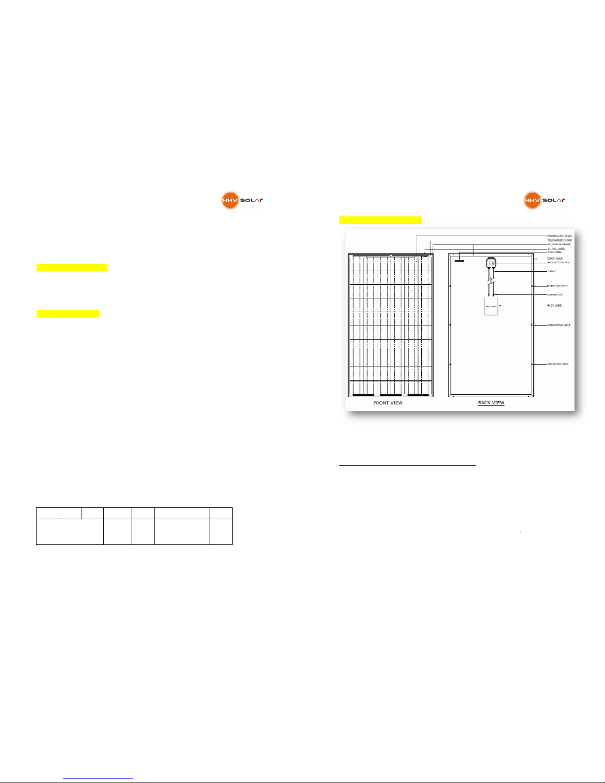
C. Components of a Solar
Module
The Modules are
classified for the application C
•
Hazardous voltage (IEC61730: higher than 50V C ; EN 61730: higher than 120V),
hazardous power applications (higher than 240W) where general contact access is
anticipated ( modules
application class are considered to meet the requirements for safety class II )
•
The objective of this manual is to provide the customer(s) clear instructions on how to
mount
the PV modules to
requirements.
•
Further, please also consult the local authorities
before taking up or mounting of the PV modules and ensure that the mounting
instructions described in
Module
classified for the application C
lass –A :
Hazardous voltage (IEC61730: higher than 50V C ; EN 61730: higher than 120V),
hazardous power applications (higher than 240W) where general contact access is
anticipated ( modules
qualified for safety thorough EN IEC 61730-
1 and
application class are considered to meet the requirements for safety class II )
The objective of this manual is to provide the customer(s) clear instructions on how to
the PV modules to
ensure compliance with certification and regulatory
Further, please also consult the local authorities
(if there any statutory requirement)
before taking up or mounting of the PV modules and ensure that the mounting
instructions described in
this manual meet their requirements.
3
Hazardous voltage (IEC61730: higher than 50V C ; EN 61730: higher than 120V),
hazardous power applications (higher than 240W) where general contact access is
1 and
-2 within this
application class are considered to meet the requirements for safety class II )
The objective of this manual is to provide the customer(s) clear instructions on how to
ensure compliance with certification and regulatory
(if there any statutory requirement)
before taking up or mounting of the PV modules and ensure that the mounting
Solar Module Installation Manual
4
D. ELECTR CAL SPEC F CAT ONS
•
The module electrical ratings are measured under Standard Test Conditions (STC) of
1 KW/M2 irradiance with an AM1.5 spectrum, and cell temperature of 25°C. Main
electrical characteristics at STC appear on each module back label. The maximum
system voltage for module is 1000V.
•
This photovoltaic module produces electricity when exposed to sunlight or other
light source. The STC Ratings are not the maximum or optimal values. The PV
modules may generate electrical voltage and current more than the STC ratings
under certain conditions. While connecting PV modules to other equipments (like
Battery/Inverter etc.) This variation must be taken into account. The voltage (Voc)
and Short Circuit Current (Isc) marked on the name plate of the module must be
multiplied by 1.25 When determine component voltage ratings, conductor current
ratings, fuse sizes and size of connectors, controls connected to the PV output.
E. GENERAL SAFETY
•
All installations must be performed in compliance with all applicable regional and
local codes or other national or international electrical standards.
•
Wear suitable protection (non slip gloves, clothes, etc.) to prevent direct contact
with 30VDC or greater, and to protect your hands from sharp edges during the
installation.
•
Use electrical insulated tools to reduce the risk of electric shock.
•
Remove all metallic jewelry prior to installation to reduce the chance of accidental
exposure to live circuits.
•
Cover the front of the modules in the PV array with an opaque material to halt
production of electricity when installing or working with a module or wiring.
•
Do not install or handle the modules when they are wet or during periods of high
wind.
•
Do not use or install broken modules.
•
If the front glass is broken or the back sheet is torn, contact with any module surface
or the frame can cause electric shock.
•
There’re no serviceable parts within the PV module. Do not attempt to repair any
part of the module.
•
Keep the junction box cover closed at all times.
•
Do not disassemble a module or remove any module part.
•
Do not artificially concentrate sunlight on a module.
•
Do not connect or disconnect modules when current from the modules or an
external source is present.
Solar Module Installation Manual
F.
UNPACK NG AND STORAGE
Precautions and General Safety
•
Store modules in a dry and ventilated room.
•
Do not allow children and unauthorized persons near the installation site or storage
area of modules.
•
Unpacking module pallet with care and
pallet. Be careful when unpacking, transporting and storing the modules.
•
Do not carry a module by its wires or junction box. Carry a module by its frame with
two or more people.
•
Do not place modules on top of each
•
Do not place excessive loads on the module or twist the module frame.
•
Do not stand, step, walk and/or jump on the module.
•
Do not carry the module on head.
•
Do not drop or place objects on the modules (such as tools.)
•
Do not mark the modules with shar
taken to avoid module back
scratches may directly affect product safety.
•
Do not leave a module unsupported or unsecured.
•
Do not change the wiring of bypass diodes.
•
Keep all electrical contacts clean and dry.
G. MODULE NSTALLAT ON
Precautions and General Safety
•
When installing modules, please ensure the
resistant roof covering rated
as Class C according to UL790 standard.
CAUT ON:
n any
circumstances
the modules, as localized high loads may induce
severe micro
may compromise module reliability. Failure to comply with
caution will void HHV Solar warranty.
Environmental conditions
•
Do not install modules near naked flames or flammable materials.
•
Do not expose modules to artificially concentra
UNPACK NG AND STORAGE
Precautions and General Safety
Store modules in a dry and ventilated room.
Do not allow children and unauthorized persons near the installation site or storage
Unpacking module pallet with care and
follow the unpacking steps marked on the
pallet. Be careful when unpacking, transporting and storing the modules.
Do not carry a module by its wires or junction box. Carry a module by its frame with
Do not place modules on top of each
other.
Do not place excessive loads on the module or twist the module frame.
Do not stand, step, walk and/or jump on the module.
Do not carry the module on head.
Do not drop or place objects on the modules (such as tools.)
Do not mark the modules with shar
p instrument. Particular attention should be
taken to avoid module back
sheet to come in contact with sharp objects, as
scratches may directly affect product safety.
Do not leave a module unsupported or unsecured.
Do not change the wiring of bypass diodes.
Keep all electrical contacts clean and dry.
Precautions and General Safety
When installing modules, please ensure the
assembly is mounted over a fire
resistant roof covering rated
for the application. HHV Solar
modules have been
as Class C according to UL790 standard.
circumstances
DO NOT STAND OR STEP on
the modules, as localized high loads may induce
severe micro
-cracks in the cells
, which in turn
may compromise module reliability. Failure to comply with
this
caution will void HHV Solar warranty.
Do not install modules near naked flames or flammable materials.
Do not expose modules to artificially concentra
ted light sources.
5
Do not allow children and unauthorized persons near the installation site or storage
follow the unpacking steps marked on the
pallet. Be careful when unpacking, transporting and storing the modules.
Do not carry a module by its wires or junction box. Carry a module by its frame with
Do not place excessive loads on the module or twist the module frame.
p instrument. Particular attention should be
sheet to come in contact with sharp objects, as
assembly is mounted over a fire
modules have been
listed
DO NOT STAND OR STEP on
the modules, as localized high loads may induce
, which in turn
this
Solar Module Installation Manual
6
•
Do not immerse modules in water or constantly expose modules to water (either
fresh or salt) (i.e. from fountains, sea spray).
•
Exposing modules to salt (i.e. marine environments) and sulfur (i.e. sulfur sources,
volcanoes) risks module corrosion.
H. REQU REMENTS FOR NSTALLAT ON
•
Connect the quantity of modules that match the voltage specifications of the
inverters used in the system. Modules must not be connected together to create a
voltage higher than the permitted maximum system voltage, even under the worst
local temperature conditions.
•
A maximum of two strings can be connected in parallel without using over current
protection device (fuses…) incorporated in series within each string. Three of more
strings can be connected in parallel only if an appropriate and certified over current
protection device is installed in series with each string.
•
Modules with similar electrical performance should be connected in same series to
avoid or minimize mismatch effects in arrays.
•
Cover the module surface (glass side) with an opaque material so that no light shines on
the glass surface and ensure that there is no electricity production from the module
before making any electrical connections.
•
Be sure to disconnect Photovoltaic module from any other electrical sources like
batteries, inverters, electrical grid etc before working on the module.
•
Ensure that only people qualified in handling electrical equipments are installing these
modules.
•
Broken glass on the module is electrical safety hazard. Please replace the module
immediately in case you discover a broken module.
•
Under some conditions the photovoltaic module produces electrical current /voltage
more than specified on the rating plate. Please take appropriate measures to size the
other equipments you intent to connect to this module.
•
Please note there are no user serviceable parts inside the module and it is advised not
to disassemble the module.
•
The front surface of the module is made from high transmission tempered/toughened
glass but also could break easily if it is not handled properly. The special textured
structure on the glass ensures high light absorption at low incidence angle. Please
protect this glass surface during transportation and handling.
•
Please store the module in such a way that it does not fall off or come under falling
objects.
Solar Module Installation Manual
7
•
Please do not allow children and unauthorized persons near the installation site.
•
Do not install broken or damaged module(s).
•
Before installing the modules on the building or any other structure make sure that
the installation meets the requirements of the local building codes and regulations.
•
Be sure that the construction of the structure (Roof, facade etc.) where the modules
are being installed has enough strength.
•
A special construction may be required for the modules mounted on roof to help
proper installation.
•
Both roof construction and module installation should have effective fire resistant
materials.
•
In order to cool the modules, a minimum clearance of about 100 mm must be
provided between the back of the modules and the roof.
Optimum orientation and tilt
•
Find out the optimum orientation and tilt of the PV modules for your region to
achieve the maximum annual yield. Generation of maximum power occurs when
sunlight shines perpendicularly onto the PV modules.
Reliable ventilation
•
Sufficient clearance (at least 10 cm) between the module frame and the mounting
surface is required to allow for cooling air to circulate around the back of the
module. This also allows for condensation or moisture to dissipate.
Correct connection of plug connectors
•
Make sure that the connection is safe and tight. The plug connector should not
receive outer stress. The connector should only be used to connect the circuit. It
should never be used to turn the circuit on and off.
Use of suitable materials
•
Use special solar cable and suitable plugs only (wiring should be placed in conduit
that is sunlight resistant or, if exposed, should be sunlight resistant) in accordance
with local fire, building and electrical code. Ensure that they are in perfect electrical
and mechanical condition.
•
The permitted type of solar cable is single conductor, 4.0 10 mm
2
(8 12 AWG), 90°C
wet rated, with proper insulation to Withstand the maximum possible system
open circuit voltage (such as TUV 2PfG1169 approved). The conductor material
should be copper only. Select a suitable conductor gauge to minimize voltage drop.

Solar Module Installation Manual
8
No Shading on module
•
Utmost care to be taken while designing the modules’ layout to avoid slightest of partial
shading on the module in any point of the day in the whole year cycle.
Lightning Arrestor
•
Any installation should be supported by a properly designed appropriate Lightning
Protection System and Surge protection Device.
. F RE SAFETY
•
The devices of on roof systems can affect the fire safety of the building, improper
installations can result in a hazard in case of fire.
•
Roof mounted PV modules to be mounted over fire resistant roof.
•
Improper installation may contribute to fire hazards. Additional devices such as
ground fault indicator, fuses etc., may be required.
•
The PV module is declared as non explosion protected equipment and must not be
installed near open flames, flammable materials and vapors.
J. JUNCT ON BOX
•
HHV Solar modules of type HSTXY12xxxZ & HSTXY24xxxZ are factory fitted with
Tyco/ Cixi Renhe/ Huber & Suhner made junction boxes with approved UV
resistant cables of size 4.0 mm2 and terminated with the press fit type
connectors, fitted as per the instructions of Tyco/ Cixi Renhe/ H&S. Please do
not open the junction box as there are no user serviceable parts inside.
Table 1: Details of Junction Box used in different family of modules
Module Type Junction
Box Brand
Manufacturer
Junction Box Cable Connector
HSTXY24xxxZ –
HSTXY12xxxZ
Tyco Tyco Electronics
Studer/Tyco MC4 type
Cixi Renhe Cixi Renhe Taiyo MC4 type
H&S H&S H&S HA3
•
The module wiring MUST NOT be opened under load. Any connection and
disconnection must be made only when the current is not flowing in the module.
Solar Module Installation Manual
9
•
The cables are of equal lengths which are appropriate for series connection of the
modules. The cables are marked on them (+) and ( ) for easy identification of the
terminals.
K. BYPASS D ODES
The bypass diodes are factory fitted inside the junction box. Please do not remove these
bypass diodes. These diodes help in by passing the shaded strings of the cells and thereby
preventing the modules from heating.
Table 2: Details of Diodes used in Junction Box in different family of modules
Junction Box
Brand Diode Type V
(Volt)
(Amp) Configuration
Tyco Electronics SCHOTTKY
SL1515 40 13 4 terminals & 3 diodes
Cixi Renhe SCHOTTKY
PVS105 45 15 4 terminals & 3 diodes
H&S SCHOTTKY
PVS105 45 15 4 terminals & 2x3 diodes
L. SER ES FUSE
In order to protect the module from short circuits it is recommended to install a series fuse of
15 A. A maximum of two strings can be connected in parallel without using over current
protection device (fuses…) incorporated in series within each string. Three of more strings
can be connected in parallel if an appropriate and certified over current protection device is
installed in series with each string.
M. MODULE MOUNT NG
HHV Solar modules can be mounted on the rails using 4 mounting holes which are located at
the back of the module frame. The mounting rails must be positioned perpendicular to the
length of the module. The rails must be strong enough to support the weight of the module
and forces generated by the high wind load. The modules have to be secured using the 4
mounting holes and 6 mm stainless steel bolts and nuts. Locking washers must be included
between the frame and the bolt as shown in the Figure1.

Solar Module Installation Manual
10
Table 3: Bolting Method
Table 4: Clamping Method
MODULE TYPE H1 RANGE (mm) H2 RANGE (mm)
72 cell structure 320 420 200 – 245
60 cell structure 250 350 200 245
Load < 2400 Pa
Bolting
on long
side
frame
Mounting rails should run perpendicularly to the
long side frame
Fig.1
Solar Module Installation Manual
11
N. MECHAN CAL LOAD NG
•
The module must be mounted on secure and rigid Aluminium frames as shown in the
fig 1. This mounting will ensure that the modules are able to withstand a minimum
static load of 2400 N/mm
2
.
O. ARRAY W R NG
•
Several PV modules can be connected in series or parallel combination to get the
desired voltage and current. The maximum system voltage is 1000VDC. By connecting
the modules in series, the maximum system voltage of 1000V must not be exceeded.
•
When the modules are connected in parallel, ensure that the current not exceeding
the maximum fuse rating
•
For installation, the required extra wire for connecting the arrays, inverters etc, it is
recommended to use USE 2 or PV Wire rated for min. 90˚C, UV resistant, Copper only,
10 12 AWG.
•
Please note that the interconnecting of more than two strings requires the
installation of string fuses (15A). The maximum series fuse rating has been rated to
15 A, if more than two strings are connected in parallel, this value might be
exceeded if there is a fault.
•
It is strongly recommended to use copper wire that has a very good insulation and
resistant to sunlight. The wire diameter and insulation must be suitable for maximum
possible system voltage.
P. MAX MUM SYSTEM VOLTAGE
•
The modules of the type described in this manual are designed for a Maximum system
voltage of 1000 VDC. Please note that the module open circuit (Voc) increases with
decrease in temperature and therefore allowable maximum system voltage must take
into account the lowest temperature that is attainable in the area where the module is
intended to be used.
Q. GROUND NG
All modules have to be electrically grounded as per the National Electrical Code (USA) or in
accordance with CSA C22.1, Safety Standard for Electrical Installations, Canadian Electrical
Code, Part 1. Modules are provided with grounding holes at the back of the module frames
and the below symbol also been printed/marked near the hole for identification.
Please ensure that the modules are earthed/grounded properly as per the
local requirements. The grounding wire can be attached to the modules
using stainless steel bolts (M3) & washers. Also ensure that the grounding
wire is secured tightly to the module frame. The grounding wire size and
earthing method must be in accordance to the local requirements. In order to achieve proper

Solar Module Installation Manual
12
grounding, the star washers must go through the anodized surface of the frame to create a
conductive connection and the modules frames must be connected using a copper or copper
alloy conductor which in turn has to be connected to the earth ground electrode.
Please see the drawing below for one of the correct grounding method:
Note : The star washer shown above must go through the anodized surface of the frame
to create a conductive path.
Proper grounding can also be achieved by using
self tapping screw with a stainless steel washer to
hold the wire under the washer very firmly. It is
highly recommended to use at least two self
tapping screws per module in order to get
adequate grounding contact. Stain steel bolts
and nuts, washer only to be used to corrosion.
The screw of diameter 4.17 mm can be used and
it should at least have two full turn of threads
embedded into Aluminium frame.
Figure 2 (Grounding using stainless steel
hardware with star washers)
MPORTANT
It is always important to ensure that the grounding hardware used must not corrode itself or
induce corrosion (Galvanic effect) in the parent material.
The standard hole provided in the module frame is 4 mm. However if there is a need to drill
additional holes, the diameters specified in the table 3 can be used :
Table 5. Grounding Hole Hardware Diameters
Rated current(A) Minimum nominal thread
diameter(mm)
Pillar type
Screw type
Up to and including 10 A 3 3.5
Over 10 A including 16 A 3.5 4
Over 16 A up to and including 25 A 4 5
Over 25 A up to and including 32 A 4 5
Over 32 up to and including 40 A 5 5
Solar Module Installation Manual
13
R. CLEAN NG / MA NTENANCE
All solar modules of the types described in this manual are designed to operate in the outdoor
conditions for long periods. However it is recommended to follow the basic procedures that
are described below to get the best performance from the solar photovoltaic modules;
•
Regular maintenance is required to keep modules clear of dust, bird droppings,
seeds, pollen, leaves, branches, dirt spots and snow.
•
When there is a noticeable buildup of soiling deposits on the module surface, wash
the PV array with water and a gentle cleaning implement (a sponge) during the cool
part of the day. Dirt must never be scraped or rubbed away when dry, as this will
cause micro scratches.
•
The power output from the module is strongly influenced by the transparency of the
Cover/front glass. Over a period of time dust could accumulate on the glass and reduce
the solar light passing through the glass which in turn reduces the performance of the
module. In order to restore the module performance, clean the glass with plain water.
In most cases plain water clean is just adequate. However if there are any hard stains
they could be easily removed by gentle wiping/mopping with soft cotton/sponge.
•
Check the hardness/TDS of water; preferably it should be below 150; more than 250
to be avoided;
•
When under load, modules to be cleaned either in the early morning or after Sunset.
•
Aluminium frames could get discolored due to bird droppings. It is recommended to
use mild soap or detergent to clean the Aluminium surface. Wear gloves while
cleaning, as sharp edges on the Aluminium module can cause injury.
•
While cleaning be careful not to drop any objects on the module surface. The module
surface is made from glass and could get easily damaged. The damaged module
increases the risk of electrical shock. The damaged module must be immediately
replaced with a new module.
•
Periodic inspection of the mounting structure and electrical connections must be
carried out and any loose connections must be corrected immediately.
MPORTANT
All cleaning and maintenance operations are to be done by a trained person only. f the
modules are mounted on high roof or on an area which is at a height from the ground level,
person involved in cleaning operations must wear appropriate safety harness.
S. D SPOSAL
If the modules need to be disposed off, kindly contact the manufacturer or can be done in
accordance with the local law of land; in either case, customer is requested to intimate the
manufacturer.

Solar Module Installation Manual
14
for further information please contact:
HHV Solar
Technologies Pvt. Ltd.
No.31-34 & 37, K ADB ndustrial Area,
Phase-1, Dabaspet, Nelamangala Taluk,
Bangalore Rural Dist. - 562111, Karnataka, ND A.
Ph : +91-80-22633700; Fax : +91-80-22633811
E-mail : info@hhvsolar.com ; Web: www.hhvsolar.com
This manual suits for next models
1
Table of contents
Popular Control Unit manuals by other brands

Grundfos
Grundfos IO 111 Installation and operating instructions

Aventics
Aventics TC08 Operation/Assembly/Exchange/Expansion

HD FIRE PROTECT
HD FIRE PROTECT H3 manual

National Instruments
National Instruments SCC-TC Series user guide

Spohn & Burkhardt
Spohn & Burkhardt ESS160 installation instructions

Auta
Auta 2H ALPHANUMERIC manual


DNF Controls
DNF Controls 2034CL-Q user manual

Allen-Bradley
Allen-Bradley 1734-IB8S user manual

FALCOM
FALCOM A2 Series User manual and command reference

turck
turck excom I/O System Integration manual

Mouser Electronics
Mouser Electronics TMS320C5515 Quick start installation guide

INOXPA
INOXPA INNOVA J Installation, service & maintenance manual