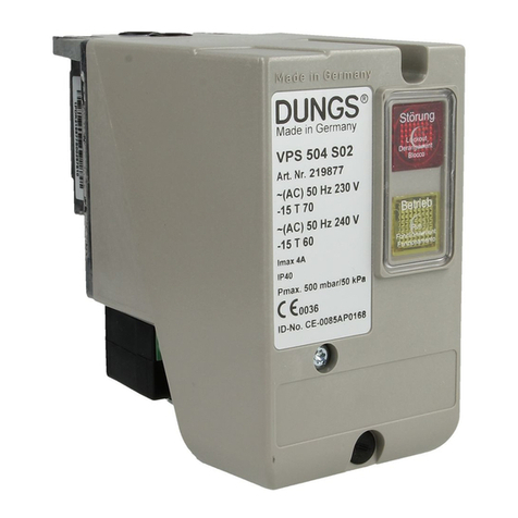
Spohn & Burkhardt ESS160 User manual

DRAFT
Spohn & Burkhardt GmbH & Co. KG, Mauergasse 5 89143, Blaubeuren Germany, Web: www.spobu.de, Mail: [email protected]
Installationshinweise – USB-Modul ESS160
1500
USB 2.0
10 Ø 4,5
11
73
56
63
73
(2)
(1)
(3)
(2)
X2.1
X2.2
X2.3
X2.4
X2.5
X2.6
X2.7
X2.8
X2.9
X2.10
X2.11
X2.12
X2.13
X2.14
X2.15
X2.16
X2.17
X2.18
X2.19
X2.20
DI 1
DI 2
DI 3
DI 4
DI 5
DI 6
DI 7
DI 8
DI 9
DI 10
DI 11
DI 12
DI 13
DI 14
DI 15
DI 16
DI 17
DI 18
DI 19
GND
X2
(digital in)
X1.1
X1.2
X1.3
X1.4
X1.5
X1.6
X1.7
X1.8
X1.9
X1.10
X1.11
X1.12
DC 5 V
GND
AI 1
AI 2
DC 5 V
GND
AI 3
AI 4
n. c.
n. c.
n. c.
n. c.
X1
(analog in)
1. Sicherheit
Das USB-Modul ESS160 (1) wird als Teil einer Gesamtanlage oder
Maschine eingesetzt. Es liegt in der Verantwortung des Betreibers,
die sichere und fehlerfreie Gesamtfunktion sicherzustellen.
Für Schäden aus einer nicht bestimmungsgemäßen Verwendung
sowie eigenmächtigen Veränderungen am Gerät, die zu Personen-
oder Sachschäden führen, übernimmt der Hersteller keine Haf-
tung.
Alle beschriebenen Arbeiten dürfen ausschließlich von ausgebil-
detem und vom Anlagenbetreiber autorisiertem und geschultem
Fachpersonal durchgeführt werden.
Als Fachpersonal darf nur berechtigt werden, wer aufgrund seiner
Ausbildung und Kenntnisse in der Lage ist, die erforderlichen Tätig-
keiten auszuführen.
2. Beschreibung
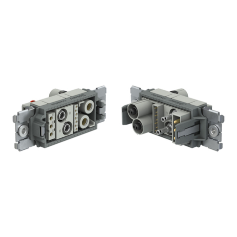
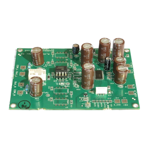
Das USB-Modul ESS160 (1) ist ein kompaktes, vergossenes USB-
Modul für die einfache Anbindung von digitalen und analogen
Signalen (z.B., von Joysticks, Befehlsgeräten,…) an ein PC-Betriebs-
system. Zu den Einsatzbereichen gehören Joysticks, Befehlsgeräte
in Fernsteuerständen, Simulatoren und Kamerasteuerungen. Das
USB-Modul ESS160 (1) verfügt über eine Doppelstockstiftleiste X1
für 4 analoge Eingänge und eine Doppelstockstiftleiste X2 für 19
digitale Eingänge. Der Anschluss an den PC erfolgt mit einer 1,5m
langen Anschlussleitung mit USB-A Stecker.
3. Technische Daten
Versorgung über USB 4,5V … 5,5V DC
Temperaturbereich -15°C bis +75°C
IP-Schutz Gehäuse wasserdicht vergossen,
Doppelstockstiftleiste IP 00
EMV EN 61000-6-2, EN 61000-6-3
Belastung gesamt
Digital Eingänge (X2)
Analog Eingänge (X1)
max. 30mA
max. 50mA
Systemvoraussetzungen Windows 7, Windows 10, Linux
X1 4 x analog IN
X2 19 x digital IN
4. Anschlussbelegung
siehe Abbildung 2 „Anschlussbelegung“
5. Mechanische Montage
1. Positionieren Sie das USB-Modul ESS160 (1) am Einbauort
und befestigen Sie das USB-Modul ESS160 (1) mit geeigneten
Schrauben durch die Befestigungslaschen (2).
6. Elektrischer Anschluss
1. Schließen Sie das Gerät (Joystick/Befehlsgerät) an den An-
schlüssen X1 und X2 an, siehe Abbildung 2 „Anschlussbelegung“.
2. Schließen Sie das USB-Modul ESS160 (1) mit der USB-An-
schlussleitung (3) an einen PC an.
7. Inbetriebnahme
Das USB-Modul ESS 160 (1) ist nach dem Anschluss an den PC ein-
satzbereit. Das USB-Modul ESS160 (1) wird automatisch erkannt
und meldet sich am PC mit„USB-Modul SpoBu“ an.
Für die nach folgenden Schritte siehe auch Abbildung 3 „Inbetriebnah-
me“
1. Geben Sie im Textfeld der Windows-Suchfunktion„USB“ ein.
2. Wählen Sie„USB-Gamecontroller einrichten“.
3. Wählen Sie im nachfolgenden Fenster „USB-Modul SPOBU“ in
der Liste aus und klicken auf„Eigenschaften“.
4. Im nachfolgenden Fenster stehen Ihnen jetzt folgende Funk-
tionen zu Verfügung:
a. „Testen“
Hier können sie die Funktionen der digitalen- und analogen
Eingänge testen.
b. „Einstellungen“
Hier können Sie die analogen Eingänge kalibrieren. Wählen
Sie„Kalibrieren“ und folgen Sie den Anweisungen.
5. Jetzt können Sie die Funktion des Gerätes testen.
8. Wartung
Das USB-Modul ESS160 (1) ist wartungsfrei.
9. Reparatur
Eine Reparatur durch den Betreiber ist nicht vorgesehen. Defekte
Geräte senden Sie bitte an Spohn & Burkhardt GmbH & Co. KG.
10. Demontage
Elektrische Anschlüsse lösen
Beachten Sie die Abschaltbedingungen der Gesamtanlage!
1. Trennen Sie die USB-Anschlussleitung (3) vom PC .
2. Trennen Sie die Leitungen von den Anschlüssen X1 und X2.
Mechanische Demontage
3. Lösen Sie die 2 Befestigungsschrauben aus den Befestigungs-
laschen (2) und nehmen Sie das USB-Modul ESS160 (1) aus
dem Einbauraum.
11. Entsorgung
Das Gerät ist gemäß den nationalen und internationalen Gesetzen
und Vorschriften zu entsorgen.
12. Mitgeltende Dokumente
Konformitätserklärung
Original – DE – 01/2020
Abbildung 1. Übersicht/Maßbild (Maße in mm) Abbildung 2. Anschlussbelegung Abbildung 3. Inbetriebnahme

DRAFT
Spohn & Burkhardt GmbH & Co. KG, Mauergasse 5 89143, Blaubeuren Germany, Web: www.spobu.de, Mail: [email protected]
Installation instructions – USB-Module ESS160
1500
USB 2.0
10 Ø 4,5
11
73
56
63
73
(2)
(1)
(3)
(2)
X2.1
X2.2
X2.3
X2.4
X2.5
X2.6
X2.7
X2.8
X2.9
X2.10
X2.11
X2.12
X2.13
X2.14
X2.15
X2.16
X2.17
X2.18
X2.19
X2.20
DI 1
DI 2
DI 3
DI 4
DI 5
DI 6
DI 7
DI 8
DI 9
DI 10
DI 11
DI 12
DI 13
DI 14
DI 15
DI 16
DI 17
DI 18
DI 19
GND
X2
(digital in)
X1.1
X1.2
X1.3
X1.4
X1.5
X1.6
X1.7
X1.8
X1.9
X1.10
X1.11
X1.12
DC 5 V
GND
AI 1
AI 2
DC 5 V
GND
AI 3
AI 4
n. c.
n. c.
n. c.
n. c.
X1
(analog in)
1. Safety
The USB module ESS160 (1) is used as part of an overall system or
machine. It is the responsibility of the operating organization to en-
sure safe, correct overall function.
The manufacturer will not accept any liability for damage due to
abnormal use, or unauthorized modications to the device that
cause injuries or damage.
All tasks on the device, as well as the integration of the device into
systems and machines, are only allowed to be undertaken by trai-
ned specialist personnel authorized and trained by the operating
organization.
Only specialist personnel who, due to their training and knowledge,
are able to undertake the necessary tasks are allowed to be autho-
rized.
2. Description
The USB module ESS160 (1) is a compact, encapsulated USB modu-
le for the simple connection of digital and analog signals (e.g. from
joysticks, command devices, …) to a PC operating system. Areas of
application include joysticks, command devices in remote control
stands, simulators and camera controls. The USB module ESS160 (1)
has a double-deck pin header X1 for 4 analog Inputs and a double-
deck pin header X2 for 19 digital inputs. The connection to the PC
is made with a 1.5m long connecting cable with USB-A connector.
3. Technical data
Supply via USB 4,5V … 5,5V DC
Temperature range -15°C to +75°C
Degree of protection IP Housing waterproof encapsulated,
double-deck pin header IP 00
EMC EN 61000-6-2, EN 61000-6-3
Electrical load in total
Digital IN (X2)
Analog IN (X1)
max. 30mA
max. 50mA
System requirements Windows 7, Windows 10, Linux
X1 4 x analog IN
X2 19 x digital IN
4. Pin assignment
see Figure 2. „Pin assignment“
5. Mechanical installation
1. Position the USB module ESS160 (1)in the installation location
and fasten the USB module ESS160 (1) using 2 suitable screws
through the fastening aps (2).
6. Electrical installation
1. Connect the device (joystick/command device) to connec-
tions X1 and X2, see Figure 2. „Pin assignment“.
2. Connect the USB module ESS160 (1) with the USB connecting
cable (3) to a PC.
7. Set up
The USB module ESS160 (1) is ready for use after connection to the
PC.
The USB module ESS160 (1) is automatically detected and logs on
to the PC with “USB module SpoBu“.
For the following steps see also Figure 3„Set up“.
1. Enter„USB“ in the text eld of the Windows search function.
2. Select „Set Up USB Game Controller“.
3. In the following window, select „USB module SPOBU“ in the
list and click on„Properties“.
4. The following functions are now available in the following
window:
a. „Testing“
Here you can test the functions of the digital and analog
inputs.
b. „Settings“
Here you can calibrate the analog inputs. Select „Calibrate“
and follow the instructions.
5. Now you can test the function of the device.
8. Servicing
The USB module ESS160 (1) is maintenance-free.
9. Repair
Repair by the operating organization is not intended. Please send
faulty devices to Spohn & Burkhardt GmbH & Co. KG .
10. Removal
Disconnect electrical connections
Note the shutdown conditions for the overall system!
1. Disconnect the USB connection cable (3) from the PC.
2. Disconnect the cables from connections X1 and X2.
Mechanical removal
3. Undo the 2 fastening screws from the fastening aps (2) and
remove the USB module ESS160 (1) out of the installation
space.
11. Disposal
The USB module ESS160 is to be disposed of as per the national and
international laws and regulations.
12. Reference documents
Declaration of conformity
Translation of the german original – 01/2020
Figure 1. Overview/Dimension drawing (Dimensions in mm) Figure 2. Pin assignment Figure 3. Set up
Table of contents
Languages:
