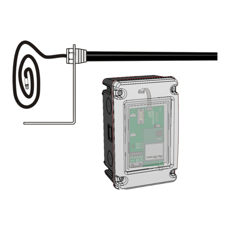
Skov DOL 530 Manual

2018.06.06 • 604066
DOL 530/DOL 630
Extension Box
Technical User Guide
English: For other language variants of this document we refer to:
Español: Para otras variantes del idioma de este documento, visite:
Français: Pour les versions dans d'autres langues de ce document veuillez consulter:
http://docs.skov.com/1174


Technical User Guide 3
DOL 530/DOL 630 Extension Box
Product and documentation changes
SKOV A/S reserve the right to change this document and the product herein described without further notice.
In case of doubt, please contact SKOV A/S.
Date of change appears from the front and the back page.
Note
•All rights reserved SKOV A/S. No part of this manual may be reproduced in any manner whatsoever
without the express written permission from SKOV A/S.
•SKOV A/S have made all reasonable efforts to ensure the accuracy of the information contained in this
manual. Should any mistakes or imprecise information occur in spite of this, SKOV A/S would
appreciate being notified thereof.
•Irrespective of the above, SKOV A/S shall not accept any liability with regard to loss or damage caused
or alleged to be caused by reliance on any information contained herein.
•Copyright 2018 by SKOV A/S.

4 Technical User Guide
DOL 530/DOL 630 Extension Box
1PRODUCT DESCRIPTION...............................................................................5
2MOUNTING GUIDE ..........................................................................................5
2.1 Checking parts......................................................................................................... 5
2.2 Mounting of extension box ..................................................................................... 6
3ELECTRICAL CONNECTION ..........................................................................7
3.1 Extension box with two I/O modules (136471) ...................................................... 7
3.2 Extension box with one I/O module (136470)........................................................ 8
4TECHNICAL DATA...........................................................................................9
4.1 Dimensioned sketch................................................................................................ 9

Technical User Guide 5
DOL 530/DOL 630 Extension Box
1 Product description
This manual deal with installation and connection of
•136470 DOL 530/630 extension box, Small 10RL with one IO type 15, 10RL 8AI 8AO
•136471 DOL 530/630 extension box, Small 20RL with two IO type 15, 10RL 8AI 8AO
The layout of the manual follows the work routines required. By following the instructions of the manual, you
will go through all steps in the correct order.
The DOL 530/630 extension box can be connected to SKOV A/S house controllers.
2 Mounting guide
2.1 Checking parts
Figure
Number of
Description
1
DOL 530/630 extension box with one or two
I/O modules.
2
Rubber sleeve for controller cabinet
4
Chipboard screw 5x80 pan TX25 A2
4
Rawlplug 8 mm
4
Technical user guide

6 Technical User Guide
DOL 530/DOL 630 Extension Box
2.2 Mounting of extension box
NOTE The extension box must be installed where it is not exposed to frost or bright sunlight.
Mount the extension box to the left or the right of the house controller.
1) Knock out knock-out pieces in the sides of the box (A) and in the side of the house controller.
2) Knock out the required number of knock-out pieces (B) at the bottom of the cabinet and mount the
plastic glands (C).
3) Prick/drill holes for the four screws (D) in the bottom section of the cabinet.
4) Correct the box to horizontal. Hold the cabinet base against the wall and mark out for the four screws.
5) Drill four 8mm holes.
6) Mount the box using the enclosed wall dowels and screws.
7) Place one or more washer(s) under one of the bottom feet if the wall is not level and the cabinet base
moves.
8) Mount the rubber sleeves (E).
House controller
Extension box right
Extension box left
House controller

Technical User Guide 7
DOL 530/DOL 630 Extension Box
3 Electrical connection
Qualified personnel must perform installation, service and fault-finding of all electrical
equipment in accordance with the applicable national and international standard EN 60204-1 and
any other EU standards that are applicable in Europe.
The installation of a power supply isolator is required for each motor and power supply to
facilitate voltage-free work on the electrical equipment. SKOV A/S does not supply the power
supply isolator.
3.1 Extension box with two I/O modules (136471)
1) Connect flat cable plug from I/O module 1 in house controller to I/O module 2 in the extension
box (A).
2) Connect flat cable plug from I/O module 2 to I/O module 3 in the extension box (B).
3) Set jumper OFF/ON (C) on the I/O module 1 of the house controller to OFF.
4) Set jumper OFF/ON (D) on the I/O module 2 of the extension box to OFF.
5) Set jumper OFF/ON (E) on the I/O module 3 of the extension box to ON.
6) Set the I/O-modules address switch (Rotary Switch) as follows:
I/O module 1 Adresse = 1
I/O module 2 Adresse = 2
I/O module 3 Adresse = 3
7) Connect the earthing contact of the extension box (F) to the earthing contact of the house controller
(G).
8) Run the earth cable through the lower rubber sleeve (H).
9) Set CAN protocol jumper (I) according to the setting on the main module. If jumper does not exist
on the main module, set CAN protocol jumper on the I/O module to Classic.
0
2
1
3
4
5
6
7
8
9
A
B
C
D
E
F
House controller
Extension box

8 Technical User Guide
DOL 530/DOL 630 Extension Box
3.2 Extension box with one I/O module (136470)
1) Connect flat cable plug from I/O module 1 in house controller to I/O module 2 in the extension
box (A).
2) Set jumper OFF/ON (C) on the I/O module 1 of the house controller to OFF.
3) Set jumper OFF/ON (D) on the I/O module 2 of the extension box to ON.
4) Set the I/O-modules address switch (Rotary Switch) as follows:
I/O module 1 Address = 1
I/O module 2 Address = 2
5) Connect the earthing contact of the extension box (F) to the earthing contact of the house controller
(G).
6) Run the earth cable through the lower rubber sleeve (H).
7) Set CAN protocol jumper (I) according to the setting on the main module. If jumper does not exist
on the main module, set CAN protocol jumper on the I/O module to Classic.
0
2
1
3
4
5
6
7
8
9
A
B
C
D
E
F
Extension box
House controller

Technical User Guide 9
DOL 530/DOL 630 Extension Box
4 Technical data
DOL 530/630 extension box
Electrical Setup
Supply voltage
230/240 V ± 10 %
Supply frequency
50/60 Hz
Power consumption
Max. 13 W
IO type 15, 10RL 8AI 8AO
8 pcs, 0–10 V DC inputs. Input impedance 2.1 MOhm
8 pcs, 0–10 V DC Outputs. Output impedance 10 Ohm*
10 relays NO/NC potential free
Max. Voltage/current with resistive load: 250Vac/5Aac
Max. Voltage/current with inductive load: 250Vac/2Aac
1 motor supply 24 V DC +/-20%, 0.4 A
Mechanical Design
Cable knock-out pieces
Twenty Ø25.5 mm for M25 screwed cable joint
Two Ø40 mm in each side for the socket
Environment
Ambient temperature, operation
(-10 to +45 °C, +14 to 113 °F)
Ambient temperature, storage
(-25 to +60 °C, -13 to +140 °F)
Ambient humidity, operation
0-80% RH
Protection class **
Splash proof IP 54
**It is assumed that the base is level, i.e. ≤ 1.5 mm difference of height and that the screws of
the cover are tightened with min. 200 Ncm.
Shipping
Dimensions
H × W × D: 120 × 380 × 400 mm
Dimensions when packed
H x W x D:206 x 395 x 595 mm
Shipping weight
3500 g
* Examples:
•I/O module output impedance = 10 ohm so the load’s input impedance must be greater than 1 kOhm = 1,000 ohm
for max. 1% error. E.g. DA 74’s AI 0-10 V input impedance = 100 kOhm: 0 => 100,000/1,000 = 100 x DA 74
inputs can be connected in parallel with one I/O output.
4.1 Dimensioned sketch

10 Technical User Guide
DOL 530/DOL 630 Extension Box

Other manuals for DOL 530
1
This manual suits for next models
1
Table of contents
Other Skov Control Unit manuals
Popular Control Unit manuals by other brands

Dewetron
Dewetron EPAD2 Series Technical reference manual

Opengear
Opengear IP Power 9258 Quick start user manual

Festo
Festo HSP AE Series manual

Thundercomm
Thundercomm TurboX D845 manual

Tektronix
Tektronix 80C14 user manual

Technische Alternative
Technische Alternative RSM610-MB Installation instructions and user manual