manuals.online logo
Brands
  1. Home
  2. •
  3. Brands
  4. •
  5. Hi-Force
  6. •
  7. Water Pump
  8. •
  9. Hi-Force AHP10 User manual

Hi-Force AHP10 User manual

INSTRUCTION MANUAL –AIR DRIVEN HYDROTEST PUMPS:
Model Series: AHP10.AHP26, AHP36, AHP58, AHP107, AHP187, AHP275, AHP425,
AHP2-036, AHP2-060, AHP2-097, AHP2-144, AHP2-237, AHP3-040, AHP3-060, AHP3-100, ATDP63 ATDP125,
ATDP216,
Hi-Force Limited –Prospect Way –Daventry –Northants NN11 8PL –United Kingdom
Tel: +44(0) 1327 301000: Fax: +44(0) 1327 706555: Website: www.hi-force.com
1.0 Inspection of the product upon receipt:
On receipt of the product, visually inspect the
item for any evidence of shipping damage.
Please note shipping damage is not covered
by warranty. If shipping damage is found notify
the carrier immediately and refrain from putting
the product into service. The carrier is
responsible for repair and replacement costs
resulting from damage in transit shipment.
2.0 Safety Precautions:
Read and follow all the instructions and safety
warnings carefully prior to use of the equipment.
Failure to do so could result in equipment
damage or failure of the equipment or personal
injury. Hi-Force will not be held responsible for
any damage to the equipment or personal
injury resulting from unsafe use of the product,
lack of maintenance or incorrect operation. If in
doubt on the correct usage of any Hi-Force
equipment, contact your nearest Hi-Force office
or distributor. If the operator has not been
trained on high pressure hydraulic equipment
and its safe use consult your local Hi-Force sales
office who can offer you training courses for
operators.
All operators should ensure that all necessary
personal protective equipment as specified by
their employer is worn when operating any
hydraulic equipment. Safety shoes, safety
glasses/ visor and protective gloves should be
worn at all times. All relevant risk assessments
should be completed prior to use of the
equipment.
Warning: All ancillary equipment to be
used with these ranges of Hydrotest
pumps MUST be rated for use at the same
operating pressure as the pump model to be
used:
Sufficient time should be allocated to
planning your hydraulic system. Make
sure that all the components are fit for the
intended use
DO NOT exceed the rated pressure of the
pump or the rated capacity of the
system to be used.
AHP SERIES –Hydrotest Pumps:
1.0 General Description:
The Hi-Force AHP range of Hydrotest pumps are
supplied from a range of 8 models with output
pressures ranging from 6 bar(87psi) to 2931bar
(42,500psi) and are suitable for use with various
fluids including water.
2.0 Before operating your Hi-Force Hydraulic
Power Pack please ensure that the following
instructions are carried out.
1. Check that there is sufficient fluid in the
reservoir. If not, top up with mains
water or suitable hydraulic oil.
2. Check that the “Pressure Let-Down
Valve” is in the open position (Turn anti-
clockwise).
3. Close off the “Air Stop Valve”. (Turn
anti-clockwise).
4. Turn the “Air pressure Regulator” anti-
clockwise until the handle becomes
free and easy.
5. Connect a suitable air supply to the
“Air Supply connection” (3/8” BSP
Female).
Please note that the maximum air
pressure supplied to the Power Pack
should never exceed 100 PSI.
6. Connect a suitable hydraulic hose
(rigid piping with screwed and coned
connections in case of very high
pressure Power Packs) to the outlet
connection. Please note that the
hydraulic hose or piping together with
adapters and couplings should have a
rated working pressure equal to the
maximum output pressure of the Power
Pack.
Hoses are available from Hi-Force Ltd or your Hi-
Force Distributor suitable for working pressures
up to 30,000 PSI. Above this pressure, stainless
steel piping together with high-pressure fittings
should be used. These are also available from
Hi-Force.
INSTRUCTION MANUAL –AIR DRIVEN HYDROTEST PUMPS:
Model Series: AHP10.AHP26, AHP36, AHP58, AHP107, AHP187, AHP275, AHP425,
AHP2-036, AHP2-060, AHP2-097, AHP2-144, AHP2-237, AHP3-040, AHP3-060, AHP3-100, ATDP63 ATDP125,
ATDP216,
Hi-Force Limited –Prospect Way –Daventry –Northants NN11 8PL –United Kingdom
Tel: +44(0) 1327 301000: Fax: +44(0) 1327 706555: Website: www.hi-force.com
Once the above instructions have been
completed the Power Pack is ready for use and
the following operating procedure can be
followed:-
1. Open the Air Stop Valve (2) (turn
clockwise) SEE FIGURE 1.
2. Turn the Air Pressure Regulator (1)
slowly clockwise until the pump begins
to reciprocate. The pump should start
on 10 to 15 PSI of air under normal
conditions.
3. Turn the Air Pressure Regulator (1)
clockwise further until 25 to 30 PSI is
reached on the Air Pressure Gauge (4),
and then allow the pump to run until all
air has been purged from the circuit.
Please note that when pressure testing
large vessels and pipes, care should be
taken to bleed off any air within the
object being tested.
4. Turn the Air Pressure Regulator (1) anti-
clockwise until zero pressure is reached
on the Air Pressure Gauge (4).
5. Close the Pressure Let-Down Valve (3)
(Turn clockwise).
6. Close any further “Air Vent” valves,
external to the Power Pack once all air
has been purged from the total system.
7. Turn the Air Pressure Regulator (1) slowly
clockwise until the desired hydraulic
pressure is reached on the High Pressure
Gauge (5)
Note
If the object being tested is large it will take a
while before the pressure builds up in the system
and registers on the high pressure gauge. Care
should be taken not to set the air driving pressure
too high whilst being unattended as this may
lead to the object under test being over
pressurised.
The air drive pressure can be pre-set if desired by
closing off the air stop valve prior to use and
winding the air pressure regulating valve
clockwise until the required air pressure is
registered on the air pressure gauge.
The air pressure should ideally be set slightly
below that desired so that it can be raised to the
correct amount once the output pressure has
built up and the pump has stalled out.
The pump can then be started and stopped by
using the air stop valve only if preferred.
Once set the pump will maintain the set pressure
indefinitely and make up any fluid losses within
the hydraulic system automatically.
To let down pressure
1. Close off the Air Stop Valve (2) (Turn
anti-clockwise).
2. Turn the Air Pressure Regulator (1) anti-
clockwise until the Air Pressure Gauge
(4) is reading zero pressure.
3. Open slowly the Pressure Let-Down
Valve (3) (Turn anti-clockwise) until the
high-pressure gauge reads zero.
4. Disconnect the hydraulic hose from the
high-pressure outlet connection.
5. Disconnect the air supply from the “Air
Supply Connection”.
Figure 1
AHP2 SERIES –Hydrotest Pumps:
1.0 General Description:
The Hi-Force AHP2 range of Hydrotest pumps
are supplied from a range of 5 models with
output pressures ranging from 17 bar(246psi) to
1634bar (23700psi) and are suitable for use with
various fluids including water.
2.0 Before operating your Hi-Force Hydraulic
Power Pack please ensure that the following
instructions are carried out.
1. Check that there is sufficient fluid in the
reservoir. If not, top up with mains
water or suitable hydraulic oil.
2. Check that the “Pressure Let-Down
Valve” is in the open position (Turn anti-
clockwise).
INSTRUCTION MANUAL –AIR DRIVEN HYDROTEST PUMPS:
Model Series: AHP10.AHP26, AHP36, AHP58, AHP107, AHP187, AHP275, AHP425,
AHP2-036, AHP2-060, AHP2-097, AHP2-144, AHP2-237, AHP3-040, AHP3-060, AHP3-100, ATDP63 ATDP125,
ATDP216,
Hi-Force Limited –Prospect Way –Daventry –Northants NN11 8PL –United Kingdom
Tel: +44(0) 1327 301000: Fax: +44(0) 1327 706555: Website: www.hi-force.com
3. Close off the “Air Stop Valve”. (Turn
anti-clockwise).
4. Turn the “Air pressure Regulator” anti-
clockwise until the handle becomes
free and easy.
5. Connect a suitable air supply to the
“Air Supply connection” (3/8” BSP
Female).
Please note that the maximum air
pressure supplied to the Power Pack
should never exceed 100 PSI.
6. Connect a suitable hydraulic hose
(rigid piping with screwed and coned
connections in case of very high
pressure Power Packs) to the outlet
connection. Please note that the
hydraulic hose or piping together with
adapters and couplings should have a
rated working pressure equal to the
maximum output pressure of the Power
Pack.
Hoses are available from Hi-Force Ltd or your Hi-
Force Distributor suitable for working pressures
up to 30,000 PSI. Above this pressure, stainless
steel piping together with high-pressure fittings
should be used. These are also available from
Hi-Force.
Once the above instructions have been
completed the Power Pack is ready for use and
the following operating procedure can be
followed:-
1. Open the Air Stop Valve (2) (turn
clockwise) SEE FIGURE 1.
2. Turn the Air Pressure Regulator (1)
slowly clockwise until the pump begins
to reciprocate. The pump should start
on 10 to 15 PSI of air under normal
conditions.
3. Turn the Air Pressure Regulator (1)
clockwise further until 25 to 30 PSI is
reached on the Air Pressure Gauge (4),
and then allow the pump to run until all
air has been purged from the circuit.
Please note that when pressure testing
large vessels and pipes, care should be
taken to bleed off any air within the
object being tested.
4. Turn the Air Pressure Regulator (1) anti-
clockwise until zero pressure is reached
on the Air Pressure Gauge (4).
5. Close the Pressure Let-Down Valve (3)
(Turn clockwise).
6. Close any further “Air Vent” valves,
external to the Power Pack once all air
has been purged from the total system.
7. Turn the Air Pressure Regulator (1) slowly
clockwise until the desired hydraulic
pressure is reached on the High Pressure
Gauge (5)
Note
If the object being tested is large it will take a
while before the pressure builds up in the system
and registers on the high pressure gauge. Care
should be taken not to set the air driving pressure
too high whilst being unattended as this may
lead to the object under test being over
pressurised.
The air drive pressure can be pre-set if desired by
closing off the air stop valve prior to use and
winding the air pressure regulating valve
clockwise until the required air pressure is
registered on the air pressure gauge.
The air pressure should ideally be set slightly
below that desired so that it can be raised to the
correct amount once the output pressure has
built up and the pump has stalled out.
The pump can then be started and stopped by
using the air stop valve only if preferred.
Once set the pump will maintain the set pressure
indefinitely and make up any fluid losses within
the hydraulic system automatically.
To let down pressure
1. Close off the Air Stop Valve (2) (Turn
anti-clockwise).
2. Turn the Air Pressure Regulator (1) anti-
clockwise until the Air Pressure Gauge (4) is
reading zero pressure.
3. Open slowly the Pressure Let-Down
Valve (3) (Turn anti-clockwise) until the
high-pressure gauge reads zero.
4. Disconnect the hydraulic hose from the
high-pressure outlet connection.
5. Disconnect the air supply from the “Air
Supply Connection”.
Figure 1
INSTRUCTION MANUAL –AIR DRIVEN HYDROTEST PUMPS:
Model Series: AHP10.AHP26, AHP36, AHP58, AHP107, AHP187, AHP275, AHP425,
AHP2-036, AHP2-060, AHP2-097, AHP2-144, AHP2-237, AHP3-040, AHP3-060, AHP3-100, ATDP63 ATDP125,
ATDP216,
Hi-Force Limited –Prospect Way –Daventry –Northants NN11 8PL –United Kingdom
Tel: +44(0) 1327 301000: Fax: +44(0) 1327 706555: Website: www.hi-force.com
AHP3 SERIES –Hydrotest Pumps:
1.0 General Description
The Hi-Force AHP3 range of Hydrotest pumps
are supplied in a range of 3 models with output
pressures ranging from 42 bar(609psi) to 700bar
(10000psi) and are suitable for use with various
fluids including water.
2.0 Before operating your Hi-Force Hydraulic
Power Pack please ensure that the following
instructions are carried out.
1. Connect the liquid supply to the pump
inlet port (1 ¼” NPT.) This is normally from a
reservoir tank.
2. Ensure that the liquid is filtered before
reaching the pump unit liquid inlet port.
3. Hydraulic oil (ISO 10 or 32) or water
can be used. When using water, a Glycol
additive to the water will reduce seal wear in
the unit.
4. Check the air lubricator bottle is filled
(use any light grade lubricating oil –SAE 15). To
top up undo the screw on top of the bottle and
top up.
(Important Safety note: Ensure the air supply is
disconnected when filling the bottle.)
5. The lubricator is factory set to deliver 1
drop every 25 strokes of the pump. The red
knob is used to affect this setting.
6. Connect the air supply line to the
pump inlet (1/2” BSP) Min recommended pipe
size ½ bore. Air requirement is 70-100psi, 56
S.C.F.M. Ensure the air on/off valve is closed.
7. The item requiring hydraulic pressure
connection may now be connected to the
outlet block. ½” NPTF
NB use only fittings and tubing, suitable for the
maximum pressure performance of the pump.
Once the above instructions have been
completed the Power Pack is ready for use and
the following operating procedure can be
followed:-
1. Make sure the Isolator valve and
pressure let down valve is open and
the air pressure regulator is turned fully
anticlockwise. Direct the drain hose
into a suitable location as fluid will be
discharged from this once the pump
starts.
2. Open the air on/off valve and turn the
regulator clockwise until the pump
starts to cycle. Increase the air pressure
until the pump is running at around 100
cycles per minute. Allow the pump to
cycle for approximately two minutes,
this will purge the pump of any air.
3. NB: This will not normally purge air from
the item under test. Additional vent
points (or other precautions) will be
required to ensure the item under test is
completely filled with liquid before
pressurisation otherwise a dangerous
situation may occur.
4. Stop the pump by closing the air on/off
valve. Should any black oil be visible
around the pump air motor exhaust,
this should not give rise to concern, as
lubricated air is fed to the pump, and
excess oil will be discarded via the
exhaust.
To apply hydraulic pressure:-
5. Close the pressure let down valve.
6. Make sure the isolation valve is open.
7. Turn the air pressure regulator valve
fully anticlockwise.
8. Open the air ON/OFF valve and
gradually increase air pressure by
turning the pressure-regulator
clockwise until the pump starts to
cycle. This will deliver liquid to the item
under test and (once all vent ports are
closed) allow hydraulic pressure to
build up. The pressure may build up
very slowly depending on the size of
the item under test. This pressure will be
indicated on the large pressure gauge.
9. The hydraulic output pressure is directly
proportional to the air inlet pressure.
The pump will stall when the hydraulic
pressure reaches a balance point
directly related to the air pressure
setting. To increase the hydraulic
pressure further, the air pressure must
be increased.
10. This feature can be used to maintain
pressure in a vessel over a period of
time. The pump will cycle occasionally
to keep the pressure topped up
against slight leakage loss.
INSTRUCTION MANUAL –AIR DRIVEN HYDROTEST PUMPS:
Model Series: AHP10.AHP26, AHP36, AHP58, AHP107, AHP187, AHP275, AHP425,
AHP2-036, AHP2-060, AHP2-097, AHP2-144, AHP2-237, AHP3-040, AHP3-060, AHP3-100, ATDP63 ATDP125,
ATDP216,
Hi-Force Limited –Prospect Way –Daventry –Northants NN11 8PL –United Kingdom
Tel: +44(0) 1327 301000: Fax: +44(0) 1327 706555: Website: www.hi-force.com
11. The Isolation valve may be closed if
desired to maintain pressure in the item
under test, but it must be remembered
that if this is done, the pump will not
automatically keep the pressure
topped up.
To release hydraulic pressure:
Make sure the drain hose is directed into a
suitable container or back to the reservoir and
open the pressure let down valve. Liquid will be
discharged along the drain hose.
When releasing hydraulic pressure, it is
important to do so slowly to prevent possible
damage to the hydraulic pressure gauge.
TROUBLE SHOOTING GUIDE ALL AHP MODELS.
Pump will not start:
Check the mains air supply.
Check the regulated air pressure is
available via the air pressure gauge,
mounted on the air regulator.
Check the air valve is turned ON.
If the pump will still not actuate it will
require inspection.
Pump will not build up pressure:
Insufficient air pressure causing the
pump to stall.
Pressure release valve, not closed.
Close to build up pressure.
Insufficient hydraulic fluid, available
from the reservoir.
Tube connections loose in system,
check and rectify.
Strainer in pump suction blocked,
check and clean if necessary.
Loss of pressure may also be caused by
one of two reasons, the hydraulic
check valves have developed a leak,
or the fluid is bleeding past the seals in
the hydraulic cylinder. Get the unit
serviced or repaired.
Pump not running properly:
If the pump appears to be short
stroking and running too fast without
pumping properly, it usually indicates
that the air check assembly is not
working as it should be. Get the unit
repaired/serviced.
Should the pump commence to run
erratically and in a jerky manner after a
period of time it is usually an indication
that a seizing action is taking place in
the hydraulic piston/cylinder assembly.
Foreign matter such as dirt, grit or
chemicals that do not have sufficient
lubrication qualities being present in
the fluid supply usually causes this. If
the hydraulic piston and cylinder have
not been damaged a thorough
cleaning will normally solve this. The
unit may require service or repair.
For maximum volume of flow, make
sure that a sufficient flow of air is
supplied to the pump. Using a smaller
pipe than the “Air In” port of the pump
will not allow it to run at its full rated
capacity. Long runs of relatively small
pipe supplying air to the pump will
have the same effect.
If an excessive amount of oil or water is
coming through the pump air exhaust,
check the following.
A) The lubricating unit on the air supply
is delivering too much oil. Adjust to
about one drop of oil for every 20
strokes of the pump.
B) The filtering unit in the air supply is
not functioning correctly. The bowl
should be cleaned periodically to
ensure delivery of clean air to the
pump.
C) The fluid being pumped may be
leaking past the seals in the hydraulic
cylinder into the air motor. The unit will
require inspection and repair.
SERVICING
The pack is designed for long and trouble free
service, in a rugged environment with a
minimum of servicing. Regular servicing is
confined to:
Topping up the air lubricator.
Regular draining of the air filter bowl.
Occasional cleaning of the air filter
bowl using warm soapy water only.
WARNING: shut off the air supply before
removing the air filter bowl.
General Arrangement of Pump unit:
INSTRUCTION MANUAL –AIR DRIVEN HYDROTEST PUMPS:
Model Series: AHP10.AHP26, AHP36, AHP58, AHP107, AHP187, AHP275, AHP425,
AHP2-036, AHP2-060, AHP2-097, AHP2-144, AHP2-237, AHP3-040, AHP3-060, AHP3-100, ATDP63 ATDP125,
ATDP216,
Hi-Force Limited –Prospect Way –Daventry –Northants NN11 8PL –United Kingdom
Tel: +44(0) 1327 301000: Fax: +44(0) 1327 706555: Website: www.hi-force.com
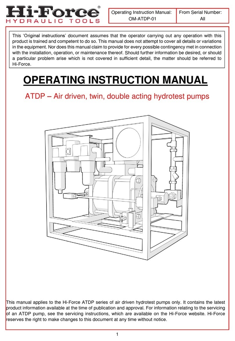
ATDP SERIES –Hydrotest Pumps:
1.0 General Description
The Hi-Force ADTP range of Hydrotest pumps
are supplied in a range of 3 models with output
pressures ranging from 87 bar(1260psi) to
1489bar (21600psi) and are suitable for use with
various fluids.
The ADTP air driven liquid pump range work on
an automatic reciprocating differential area
piston principle that uses large area air drive
pistons connected to smaller area hydraulic
pistons to convert compressed air power into
hydraulic power.
The ADTP pump range has a double acting
motion incorporating two hydraulic cylinder and
piston assemblies, as liquid is introduced into one
hydraulic cylinder on the pump suction stroke,
liquid is automatically delivered from the
second high pressure cylinder at the same time
on the pump delivery stroke and vice versa.
When the pump reaches the end of its stroke the
spool valve in the air change over valve motor
automatically shifts, reversing the pump
direction; hence delivery flow is relatively
smooth with only a small interruption in flow
(dwell) as the pump air pistons change
direction.
The units consist of a robust framework painted
to Hi-Force standard colour, fitted with an air
driven hydraulic pump and complete with all
necessary hydraulic accessories i.e. a 150mm
diameter hydraulic pressure gauge, a hydraulic
pressure release valve and all interconnecting
pipe-work fittings and adaptors, terminating at
a single high pressure outlet connection port.
Pneumatic accessories include an air filter, air
pressure regulating valve, oil lubricator, air
gauge and air on/off valve.
A fluid inlet connection is provided and a Y
type fluid strainer and fluid relief valve set at
approximately 10 bar is fitted between this
connection and the pump inlet check valves.
Provision is provided for fluid drainage via a
nylon hose connected to the hydraulic pressure
release valve.
The ATDP63 has a maximum recommended
working pressure of 434Bar (6,295psi) on the
hydraulic pressure circuit.
The hydraulic pressure to be generated by the
air driven pump is dependent upon the air
pressure applied i.e.
Pump ratio 63/1: 1psig air drive pressure
applied can generate 63psig hydraulic
pressure.
The ATDP125 has a maximum recommended
working pressure of 862Bar (12502psi) on the
hydraulic pressure circuit.
The hydraulic pressure to be generated by the
air driven pump is dependent upon the air
pressure applied i.e.
Pump ratio 125/1: 1psig air drive pressure
applied can generate 125psig hydraulic
pressure.
The ATDP216 has a maximum recommended
working pressure of 1489Bar (21596psi) on the
hydraulic pressure circuit.
INSTRUCTION MANUAL –AIR DRIVEN HYDROTEST PUMPS:
Model Series: AHP10.AHP26, AHP36, AHP58, AHP107, AHP187, AHP275, AHP425,
AHP2-036, AHP2-060, AHP2-097, AHP2-144, AHP2-237, AHP3-040, AHP3-060, AHP3-100, ATDP63 ATDP125,
ATDP216,
Hi-Force Limited –Prospect Way –Daventry –Northants NN11 8PL –United Kingdom
Tel: +44(0) 1327 301000: Fax: +44(0) 1327 706555: Website: www.hi-force.com
The hydraulic pressure to be generated by the
air driven pump is dependent upon the air
pressure applied i.e.
Pump ratio 216/1: 1psig air drive pressure
applied can generate 216psig hydraulic
pressure.
PREPARATION FOR USE.
It is recommended to use good quality clean &
dry air (without moisture content) to drive the air
driven pump unit. As the air pressure drops at the
pump exhaust ports, the air will cool and any
water droplets in the air can freeze prematurely
due to temperature variation. For this reason we
include and recommend the use of ‘Killfrost’ at
all times to be placed in the installed pump oil
lubrication bottle. The lubricator bottle drop
feed rate is advised at 1 drop per 20 pump
strokes.
If for any reason the lubricator is not used, the air
motor should be disassembled, inspected and
repacked with suitable compound grease every
1 million strokes. Silicone type grease is prone to
stiffening when not in use, at a minimum the
grease should be changed after a 6month idle
period and every 12 months in a scheduled
routine service interval at a minimum.
Connect the hydraulic pressure outlet port to
the equipment to be pressurised via a flexible
hose assembly or via a rigid pipe-work system.
Ensure that all attached hose, pipe-work and
fittings are rated suitably to match, at a
minimum, or exceed the maximum working
pressure rating of the pump unit.
Direct the provided drain hose into a suitable
container or drain.
Connect a 1” bore air supply hose to the power
pack air inlet port. Use appropriately pressure
rated air hose and fittings for this purpose, these
components must be rated at a higher working
pressure than the maximum supply air pressure
that can be applied to the power pack. (1/2”
bore air supply tubing is the smallest size that will
allow the pump to operate).
Ensure that the air on/off valve on the pump is in
the closed before switching on the air supply.
(Note: To achieve the potential maximum
working pressure and output flow capability,
ensure an air supply of 7 bar (100psi) is available
with a flow rate of 212 SCFM (6M³/min). The use
of a smaller bore air hose or a smaller SCFM
volume supply is acceptable but will diminish the
maximum potential flow-rate from the pump.
Make connections to the fluid inlet port using
suitably rated hose, pipe-work and fittings and a
fluid isolation valve. The fluid inlet hose and
fittings bore is recommended to be not less than
1” bore.
(Once the pump has raised hydraulic pressure
DO NOT close the fluid inlet isolation valve).
Ensure the water supply is sufficient and only at
7 bar maximum pressure. It is advisable to ensure
clean water (fluid) is used as this prevents any
possible chance of debris contaminating the
pump check valves (Y type strainer filter built in
pump unit water line).
If fluid is being supplied from a tank ensure the
tank is sited close to the fluid inlet port on the
power pack or sited above the level of the fluid
inlet port (positive head/displacement pump).
Reducing the fluid supply inlet hose/pipe bore or
supplying water from a tank at a lower level
than the pump inlet port may cause pump
cavitation’s and potential damage, so should
always be avoided. DO NOT run the pump dry,
as this will damage the hydraulic components.
PRINCIPLE STEPS OF OPERATION
1) Check that the pump on/off air valve is
closed, and that the hydraulic pressure release
valve is in the open position.
2) Adjust the pump air pressure-regulating valve
anticlockwise until it is fully wound out. Switch
on the air supply to the pump by external
means.
3) Plug the hydraulic outlet connection.
4) Turn on the water supply to the pump. As long
as the water supply is above approximately
0.7bar (10 psi) the water will flow through the
pump and through the drain hose attached to
the pressure release valve, bleeding the system.
If not (flowing water) turn the pump air pressure-
regulating valve slowly clockwise until 15-20 psi is
shown on the air pressure regulators own air
pressure gauge, the pump will operate pumping
the inlet water supply to drain.
5) Turn the pump air on/off valve to the off
position and close the hydraulic pressure release
valve once any air bubbles, seen in the nylon
drain hose, have disappeared and the system is
bled properly.
6) To use the pump:
Open the pump air on/off valve.
INSTRUCTION MANUAL –AIR DRIVEN HYDROTEST PUMPS:
Model Series: AHP10.AHP26, AHP36, AHP58, AHP107, AHP187, AHP275, AHP425,
AHP2-036, AHP2-060, AHP2-097, AHP2-144, AHP2-237, AHP3-040, AHP3-060, AHP3-100, ATDP63 ATDP125,
ATDP216,
Hi-Force Limited –Prospect Way –Daventry –Northants NN11 8PL –United Kingdom
Tel: +44(0) 1327 301000: Fax: +44(0) 1327 706555: Website: www.hi-force.com
Slowly adjust the pump air pressure-regulating
valve clockwise, the pump will reciprocate and
start to displace fluid into the system and build
up pressure, the pressure generated can be
viewed on the hydraulic pressure gauge.
The maximum pressure achievable at various
air pressures can be seen on the ATDP
brochure page under the heading “Max-
output pressure at airline input pressure” e.g.
ATDP63 if 80 psi air pressure is applied then the
maximum pressure the pump can generate is
approximately 80psi x the pump ratio 63/1 =
5,040psi (347bar). ATDP125 if 80 psi air pressure is
applied then the maximum pressure the pump
can generate is approximately 80psi x the
pump ratio 125/1 = 10,000psi (700bar). ATDP216
if 80 psi air pressure is applied then the
maximum pressure the pump can generate is
approximately 80psi x the pump ratio 216/1 =
17280psi (1191bar).
If a slower pump cycle rate is required the drive
air pressure can be reduced by turning the air
pressure regulating valve anticlockwise and/or
by partially closing the pump air on /off valve
The pump can operate as a transfer pump filling
the vessel under test with liquid.
The pump will gradually and naturally start to
cycle at a slower rate as the pressure in the
vessel under test increases until it stops (stalls)
when a balance of forces is reached i.e. when
the air drive pressure x air drive piston area = stall
pressure x driven hydraulic piston area.
The pump will hold pressure indefinitely unless a
leak occurs, at which time the pump will
automatically cut in once the leak rate reaches
a certain level to try to maintain the pressure in
the system.
If the air supply is turned to the OFF position the
hydraulic pressure generated will hold on the
pumps integral check valves (in small volume
systems the hydraulic pressure may fall slightly
and then stop whilst the check valve balls
reseat, this is normal).
The pump will continuously stroke if the circuit is
open (flushing mode).
Close the air start/stop valve to stop the pump
at any point, if required.
Once the test is completed to release hydraulic
system pressure:
Turn the air on/off valve to the off position
Turn the air pressure- regulating valve
anticlockwise until it fully is wound out
Slowly open the pressure release valve and fluid
will return via the drain hose to drain until zero
pressure is indicated on the pump hydraulic
pressure gauge.
It is possible to pre-set the pump so it stalls
automatically at the desired pressure. This can
be done by plugging the pressure outlet port
and operating the pump. Adjust the air pressure
regulator gradually upwards such that the
pump stalls at the correct pressure. Release the
pressure by opening the pressure release valve.
Close the pressure release valve once more to
check the set pressure. Provided that no
adjustments are made the pump will repeat this
set pressure when connected to a pressure
vessel.
FAULT FINDING
ALL NORMAL RECOMMENDED SAFETY
PRECAUTIONS SHOULD BE TAKEN WHEN
PERFORMING MAINTENANCE ON HYDRAULIC
AND PNEUMATIC EQUIPMENT.
1. PUMP NOT RUNNING PROPERLY OR
ERRATICALLY OR STOPS OPERATING
(a) Pump mufflers beginning to block
with ice or iced up.
(b) Pump fluid supply starved causing
cavitations or irregular pumping
action
(c) Pump air changeover valve sticking
or pump external air pilot switches
not engaging properly
(d) Insufficient lubrication
(e) Air supply starved
(f) Dirty air supply
.
2. LOSS OF HYDRAULIC PRESSURE
(a) Insufficient fluid supply
(b) Hydraulic check valves in pump
leaking
(c) Hydraulic fluid leaking past seals in
pump (Fluid can be seen leaking
from the vent hole under one or
each hydraulic cylinder).
(d) Leak from pipe- work
(e) Hydraulic pressure release valve
leaking back to drain or left partially
open accidentally
INSTRUCTION MANUAL –AIR DRIVEN HYDROTEST PUMPS:
Model Series: AHP10.AHP26, AHP36, AHP58, AHP107, AHP187, AHP275, AHP425,
AHP2-036, AHP2-060, AHP2-097, AHP2-144, AHP2-237, AHP3-040, AHP3-060, AHP3-100, ATDP63 ATDP125,
ATDP216,
Hi-Force Limited –Prospect Way –Daventry –Northants NN11 8PL –United Kingdom
Tel: +44(0) 1327 301000: Fax: +44(0) 1327 706555: Website: www.hi-force.com
General Arrangement of ATDP Pump Range.

This manual suits for next models

18

Other Hi-Force Water Pump manuals

Hi-Force MHP100 User manual

Hi-Force

Hi-Force MHP100 User manual

Hi-Force HEP2 Instruction Manual

Hi-Force

Hi-Force HEP2 Instruction Manual

Hi-Force HPF Series Instruction Manual

Hi-Force

Hi-Force HPF Series Instruction Manual

Hi-Force Premium TPA-A Series Instruction Manual

Hi-Force

Hi-Force Premium TPA-A Series Instruction Manual

Hi-Force HEP3 User manual

Hi-Force

Hi-Force HEP3 User manual

Hi-Force HP110 User manual

Hi-Force

Hi-Force HP110 User manual

Hi-Force BPP107 User manual

Hi-Force

Hi-Force BPP107 User manual

Hi-Force HP110 Instruction Manual

Hi-Force

Hi-Force HP110 Instruction Manual

Hi-Force HP227D Manual

Hi-Force

Hi-Force HP227D Manual

Hi-Force AHP1120б Series User manual

Hi-Force

Hi-Force AHP1120б Series User manual

Hi-Force AHP-BTU Series Instruction Manual

Hi-Force

Hi-Force AHP-BTU Series Instruction Manual

Hi-Force TPE-A Series Instruction Manual

Hi-Force

Hi-Force TPE-A Series Instruction Manual

Hi-Force HPX2800 User manual

Hi-Force

Hi-Force HPX2800 User manual

Hi-Force AHP1120 Series User manual

Hi-Force

Hi-Force AHP1120 Series User manual

Hi-Force ALUMINIUM HP211 Instruction Manual

Hi-Force

Hi-Force ALUMINIUM HP211 Instruction Manual

Hi-Force HEP4 Series Instruction Manual

Hi-Force

Hi-Force HEP4 Series Instruction Manual

Hi-Force ATDP63 Instruction Manual

Hi-Force

Hi-Force ATDP63 Instruction Manual

Hi-Force HTWP Series Instruction Manual

Hi-Force

Hi-Force HTWP Series Instruction Manual

Hi-Force HPP Series Instruction Manual

Hi-Force

Hi-Force HPP Series Instruction Manual

Popular Water Pump manuals by other brands

DAB FK Instruction for installation and maintenance

DAB

DAB FK Instruction for installation and maintenance

Master 540094 owner's manual

Master

Master 540094 owner's manual

EHEIM Compact+ 2000 manual

EHEIM

EHEIM Compact+ 2000 manual

Pentair HYDROMATIC NSPG 200 Installation and service manual

Pentair

Pentair HYDROMATIC NSPG 200 Installation and service manual

Conrad 57 01 00 operating instructions

Conrad

Conrad 57 01 00 operating instructions

Ismatec MasterFlex Reglo ICC operating manual

Ismatec

Ismatec MasterFlex Reglo ICC operating manual

PondMAX Ultra CW750 instruction manual

PondMAX

PondMAX Ultra CW750 instruction manual

Saci VSD magnus Installation and maintenance manual

Saci

Saci VSD magnus Installation and maintenance manual

DAB MULTI INOX instruction manual

DAB

DAB MULTI INOX instruction manual

RIDGID DP-13 operating instructions

RIDGID

RIDGID DP-13 operating instructions

Beckett M60A instructions

Beckett

Beckett M60A instructions

Grundfos SMART Digital XL DDA Installation and operating instructions

Grundfos

Grundfos SMART Digital XL DDA Installation and operating instructions

EasyPro EP120 Instructions for Operation, Safety, Warranty

EasyPro

EasyPro EP120 Instructions for Operation, Safety, Warranty

FILL-RITE FR300V Series Installation and operation manual

FILL-RITE

FILL-RITE FR300V Series Installation and operation manual

battioni Pagani ELBA Instruction manual for use and maintenance

battioni Pagani

battioni Pagani ELBA Instruction manual for use and maintenance

MSA 488543 Operation and maintenance

MSA

MSA 488543 Operation and maintenance

Grundfos CR 95 Installation and operating instructions

Grundfos

Grundfos CR 95 Installation and operating instructions

Tecnosystemi TSC100023 user manual

Tecnosystemi

Tecnosystemi TSC100023 user manual

manuals.online logo
manuals.online logoBrands
  • About & Mission
  • Contact us
  • Privacy Policy
  • Terms and Conditions

Copyright 2025 Manuals.Online. All Rights Reserved.