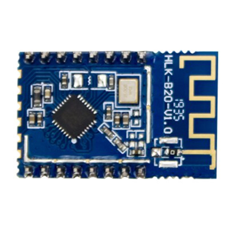
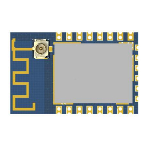
Hi-Link HLK-B36 User manual

Shenzhen Hi-Link Electronic Co., Ltd.
HLK-B36 User Manual
Version:V1.00 Revised date:08/12/2021 Reserved ©Shenzhen Hi-Link Electronic Co., Ltd

CONTENTS
1. Product Introduction...................................................................................................................1
1.1. Brief introduction............................................................................................................ 1
1.2. Product feature................................................................................................................ 1
1.3. Technical specifications...................................................................................................2
1.4. Pin introduction............................................................................................................... 3
1.5. Product packaging........................................................................................................... 5
1.6. Block diagram................................................................................................................. 5
1.7. Test board description......................................................................................................6
1.8. Power requirements.........................................................................................................6
1.9. WIFI Transmission power consumption......................................................................... 6
1.10. WIFI Receive power consumption................................................................................7
1.11. Power consumption in each working mode of WIFI.....................................................7
1.12. Output power in each mode of WIFI.............................................................................7
1.13. Receiving sensitivity in each mode of WIFI................................................................. 8
2. Function description................................................................................................................... 8
2.1. Description of wifi indicator flashing............................................................................. 8
2.2. One-key distribution mode..............................................................................................9
2.3. Serial port to WIFI STA................................................................................................ 10
2.4. Serial port to WIFI AP...................................................................................................11
2.5. Serial port working status conversion........................................................................... 11
2.6. Serial-to-network data conversion.................................................................................12
2.6.1. Module as TCP Server........................................................................................12
2.6.2. Module as TCP Client........................................................................................ 12
2.6.3. Module as UDP Server.......................................................................................13
2.6.4. Module as UDP Client........................................................................................13
2.7. Application field............................................................................................................ 14
3. AT command instructions.........................................................................................................14
3.1. Query the current module version: at+ver.....................................................................14

3.2. Local port operation:at+CLport.................................................................................. 15
3.3. Set up the serial port:at+uart......................................................................................... 15
3.4. Set DHCP:at+dhcpc...................................................................................................... 15
3.5. Set wifi connection mode:at+netmode................................................................... 16
3.6. Set tcp connection mode:at+mode................................................................................ 16
3.7. Set the remote IP when the module is used as a client:at+remoteip............................. 16
3.8. Set the remote port when the module is used as a client:at+remoteport....................... 17
3.9. Set parameter submission:at+net_commit.................................................................... 17
3.10. System restart/exit at command mode:at+reconn....................................................... 17
3.11. Set the ssid and password of the module:at+wifi_conf............................................... 18
3.12. Set the socket connection protocol:at+remotepro....................................................... 18
3.13. Set network connection parameters:at+net_ip......................................................... 18
3.14. Query STA mode network connection status:at+wifi_ConState.............................. 19
3.15. Query module MAC address:at+Get_MAC................................................................19
3.16. Set the framing length:at+uartpacklen..................................................................... 19
3.17. Set framing time:at+uartpacktimeout.......................................................................20
3.18. Set Bluetooth name:at+ble_name.............................................................................20
4. AT command control code routine........................................................................................... 20
4.1. Query configuration information...................................................................................20
4.2. Serial port to wifi client (static ip address)....................................................................22
4.3. Serial port to wifi server (dynamic ip address)............................................................. 23
4.4. Reset.............................................................................................................................. 24
4.5. Configuration software instructions.............................................................................. 25
5. Restore factory settings method............................................................................................... 26
6. Bluetooth data transparent transmission...................................................................................26
7. Bluetooth distribution network.................................................................................................27
8. Electrical characteristics...........................................................................................................28
8.1. Electrical parameters.................................................................................................28
8.2. Current waveform...................................................................................................... 29
8.2.1. AP mode............................................................................................................. 29

8.2.2. WIFI+BLE Bluetooth.........................................................................................29
8.2.3. STA mode........................................................................................................... 30
8.2.4. Default mode...................................................................................................... 30
9. Appendix A Document revision history................................................................................... 31

第1页 共 34 页
1.1. Product Introduction
HLK-B36 is a low-cost embedded UART-WIFI (serial port-wireless network) module launched
by Hi-link Electronics.
This product is based on an embedded module conforming to the network standard through a
serial interface, with a built-in TCP/IP protocol stack, which can realize the conversion between the
user's serial port and the wireless network (WIFI/BLE).
Through the HLK-B36 module, the traditional serial device can transmit its own data through
the Internet network without changing any configuration, providing a complete and fast solution for
the user's serial device to transmit data through the network.
1.2. Product Features
Support 802.11b/g/n standard, integrate ARM9, WLAN MAC/Baseband/BLE 4.2 in one
Main frequency support 120MHz
Built-in 256KB RAM/ 2MB FLASH
Working voltage 3.0-3.6V
2.4G/1T1R wifi, BLE 4.2
Support BLE fast configurate network
Support Station, Soft AP,
Support SmartConfig,support WPA/WPA2 security mode,wupport STA/AP working mode
Support 802.11b/g/n standard,HT-40
Support AP,STA and BLE mix mode
Rich peripheral interfaces, 1*SPI, 2*UART, 6*PWM, 19*GPIO
Widely used in IOT
Support multiple encryption methods WEP64/128, TKIP, AES, WPA, WPA2, WAPI

第2页 共 34 页
1.3. Technical Specifications
Table 1 Product Techinical Specification
Module
Model HLK-B36
Package In-line
Wifi
parameters
Wireless standard IEEE 802.11 b/g/n bluetooth standard:BLE 4.2
Frequency Range Wifi:2.412GHz-2.462GHz BT:2.402GHz-2.408GHz
Average power
802.11b: 16.66(@11Mbps)
802.11g: 14.82dBm (@54Mbps)
802.11n: 13.85dBm (@HT20), 10.87dBm (HT40- MCS7)
Receiving
sensitivity
802.11b: -88.4 dBm (@11Mbps ,CCK)
802.11g: -75.7dBm (@54Mbps, OFDM)
802.11n: -73.6dBm (@HT20, MCS7)
Antenna form
External: I-PEX connector
Built-in: Built-in PCB antenna
Hardware
parameters
Hardware
interface
UART,IIC,PWM,GPIO, SPI
Operating Voltage 3.3V
GPIO drive
capability
Max:16ma
Working current
Send continuously =>
Average value: ~130mA, peak value: 400mA
In normal mode =>
Average: ~130mA, Peak: 400mA
Operating
temperature
-40℃~80℃
Storage
environment
Temperature:-40~40℃,Relative humidity:10%~90%R.H.

第3页 共 34 页
Serial port
transparent
transmission
Transmission rate
110-921600bps
TCP Client
1个
Software
parameters
Wireless network
type
STA/AP
Security
Mechanism
WEP/WPA-PSK/WPA2-PSK
Encryption type
WEP64/WEP128/TKIP/AES
Firmware upgrade
Firmware upgrade
Network protocol
IPv4, TCP/UDP
User configuration
AT+ command set, one-key intelligent configuration of
network distribution
1.4. Pin introduction
Table 2 Module pin interface
Pin
Network name
Type
Directions
1
CEN
I
Chip enable, high effective
2
P26_PWM5
I/O
Bluetooth connection status indicator
pin
1: Bluetooth is connected
0: Bluetooth is disconnected
3
P24_PWM4
I/O
P24,PWM4
4
P23_TDO_F_S0
I/O
P23,ADC3
5
P22_TDI_F_SI
I/O
ES0, enter at command mode/restore
factory settings, please pull up if not used,
same as P28

第4页 共 34 页
6
P21_TMS_F_CS
I/O
P21
7
P20_TCK_F_SC
I/O
P20
8
VBAT
P
3.3V power
9
P28
I/O
Enter at command mode/restore factory
settings, please pull up if you don’t use it,
same as P22
10
P16
I/O
P16
11
P17
I/O
P17
12
P14
I/O
P14
13
P15
I/O
P15
14
P6_PWM0
I/O
P6,PWM0
15
GND
P
GND
16
P7_PWM1
I/O
Wifi indicator
17
P8_PWM2
I/O
Wifi connection status indicator
1: connected
0: Disconnected
18
P9_PWM3
I/O
Socket connection status indicator
1: connected
0: Disconnected
19
P1_URAT2_RXD
I/O
P1,UART2
20
P0_UART2_TXD
I/O
P0,UART2
21
P10_UART1_RXD
I/O
P10, UART1, used for upgrade, command
setting and transparent transmission
22
P11_UART1_TXD
I/O
P11, UART1, used for upgrade, command
setting and transparent transmission

第5页 共 34 页
1.5. Product packaging
Figure 1 HLK-B36 package size
1.6. Block diagram
Figure 2. HLK-B36 Module architecture diagram
UART
GPIO
PWM
SPI
3.3V
26MHz
HLK-B36
FLASH(2MB)
1 IPEX Connector

第6页 共 34 页
1.7. Testboard description
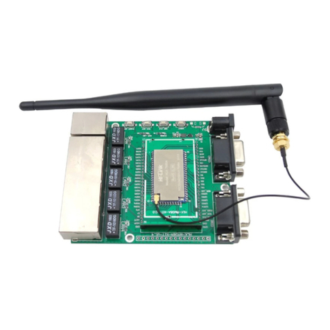
Figure 3 Test board description diagram
1.8. Power requirements
Power requirements
Power input voltage
DC:3.3±0.3V
No-load running current
130±50mA
Supply current requirements
≥800mA
1.9. WIFI transmission power consumption
WIFI transmission power consumption
Mode
Speed
Transmission power
consumption
Current(ma)
11b
11Mbps
17.5dbm
280
11g
54Mbps
11dbm
150
11n
MCS7
10dbm
130

第7页 共 34 页
1.10. WIFI receiving power consumption
Mode
Speed
Current(ma)
11b
11Mbps
100
11g
54Mbps
100
11n
MCS7
100.5
1.11. Power consumption in each working mode of WIFI
State
Description
Average current
(3v3)
Maximum current(3v3)
Unit
wifi
initialization
Turn off the radio, the
MCU is at full speed
45.2
46.3
ma
Keep wifi
connection
Keep connected to the
router
101
342
ma
Udp sending
After connecting to the AP,
send packets at full speed
through UDP
93
363
ma
SoftAP
SoftAP networking status
100.5
193.7
ma
SmartConfig
Module distribution
network status
100.8
129.5
ma
1.12. Output power in each mode of WIFI
Paremeters
Minimum
Typical value
Maximum
Unit
RF average output power,802.11b cck Mode
11m
-
17.5
-
dBm
RF average output powe,802.11g OFDM Mode
-
15
-
dBm

第8页 共 34 页
54m
RF average output power,802.11n OFDM Mode
MCS7
-
13
-
dBm
Frequency error
-10
-
10
ppm
1.13. Receiving sensitivity in each mode of WIFI
Paremeters
Minimum
Typical value
Maximum
Unit
RF average output power,802.11b cck Mode
11m
-
-91
-
dBm
RF average output power,802.11g OFDM Mode
54m
-
-74
-
dBm
RF average output power,802.11n OFDM Mode
MCS7
-
-70
-
dBm
2. Function description
HLK-B36 supports serial port to WIFI STA, serial port to WIFI AP and serial port to BLE
mode.
2.1. wifi indicator flashing description
Through the blinking mode of the LED indicator, we can quickly know the running status of the
module. The WiFi indicator of the module mainly has the following states:
1).The wifi indicator flashes periodically twice: it means that the module is in one-key
configuration mode
2). The wifi indicator flashes three times periodically: it means that the module is in STA mode
and has not been connected to the target AP hotspot
3). The wifi indicator flashes four times periodically: it means that the module is in 2.4g AP
mode, but it cannot indicate whether there is a STA client device connected

第9页 共 34 页
4). The wifi indicator flashes quickly: it means that the module is in a STA mode and connected
to the wifi hotspot. When there is data transmission, the module LED will flash quickly
2.2. One-key configuration mode
For the IOT wifi module, based on cost and performance considerations, there is no touch
screen interactive interface like a mobile phone. The user can see the ap list on the mobile phone and
click to enter the password to connect to the network. What should I do? One-key configuration is
when the wifi module is in promiscuous mode (can capture all 802.11 frames in the air), the APP
sends the SSID and password to the wifi module through UDP broadcast or multicast through a
certain encoding rule, the module parses it out, and then connects to the router. Install the Android
app HLK-TCPdemo, then select the configuration network, select the airkiss mode, enter the
password, and click to start the configuration to start the configuration. When the network
connection is successful, the module will change from double flashing to fast flashing, indicating
successful networking.
Figure 4 one-key configuration diagram

第10 页 共 34 页
When the module is in one-key network configuration status, the module needs to be set to
one-key network configuration mode. You can use the serial port configuration tool to set the module
to one-key network configuration mode.
Figure 5 setting as one key configuration
2.3. Serial port to WIFI STA
Figure 6 Moduel as STA

第11 页 共 34 页
The module converts the serial port data of the device into wifi data to achieve the purpose of
networking the device.
2.4. Serial port to WIFI AP
Figure 7 Module as ap
In AP mode, mobile phones, PCs or other wifi devices can be connected to the B36 module
through wifi, and serial devices can transmit data through the B36 module and other wifi devices
2.5. Serial port working status conversion
After the HLK-B36 is powered on, the default is the transparent transmission mode. By pulling
down the pin ES0 (PIN5) for more than 50ms and less than 2s to enter the at command mode, the
module will treat the received data as an at command and send the at comand to makes the module
enter the transparent transmission mode. After the network connection, the data received by the serial
port will be transmitted as transparent transmission data.
Figure 8 Serial port working status conversion
AT command mode
Power-on
Transparent transmission mode
transmission mode
Pull down pin for50ms
50ms
Send at command

第12 页 共 34 页
2.6. Serial-to-network data conversion
2.6.1. Module as TCP Server
Figure 9 TCP Server
In this mode, the module monitors the specified port and waits for the TCP Client to connect.
After connection, all TCP data is sent directly to the serial port, and the data from the serial port is
sent to all TCP Clients. When the module is used as a TCP Server, it supports up to 5 A TCP Client
connects to the TCP Server
2.6.2. Module as TCP Client
Figure 10 TCP Client
In this mode, the module will actively connect to the specified IP and port. All data sent from
the TCP Server will be sent directly to the serial port, and the data from the serial port will be sent to
TCP Server
TCP Client
TCP Client
TCP Client
TCP Client
TCP Server

第13 页 共 34 页
the TCP Server. Abnormal network disconnection will cause the module to reconnect actively.
2.6.3. Module as UDP Server
Figure 11 UDP Server
In this mode, the module opens the local designated port. Once the data sent to this port is
received, the module will send the data to the serial port and record the remote ip and port. The
module will only record the remote information of the last connection, and the data sent by the serial
port will be sent directly to the recorded remote ip and port.
2.6.4. Module as UDP Client
Figure 12 UDP Client
In this mode, the module directly sends serial port data to the specified ip and port, and the data
UDP Server
UDP Client
UDP Client
UDP Server

第14 页 共 34 页
returned from the server will be sent to the serial port.
2.7. Application field
Smart home;
Instrumentation;
Wi-Fi remote monitoring/control;
Toy field;
Color LED control;
Intelligent integrated management of fire protection and security;
Smart card terminals, wireless POS machines, handheld devices, etc.。
3. ATAT command instructions
Command format: In the AT command mode, the system can be configured through the AT
command of the serial port. The command format is as follows:
at+[command]=[value],[value],[value]......
All commands start with "at" and end with "\r". If the command is not encapsulated in this
format, it will not be processed, and the module will return different return values according to
different commands.
For example: "at+ver=?"
The module will return: HLK-B36 (b.1.00.120191206180224)
Query command format:
at+[command]=?
3.1. Query the current module version:at+ver
Grammar rules:
Command
type
Grammar
Return and description
Excuting an
order
at+ver=?
at+ver=HLK-B36(b.1.00.120191206180224):current
version

第15 页 共 34 页
3.2. Local port operation:at+CLport
Command
type
Grammar
Return and description
Set
instruction
at+CLport=8080
at+CLport=8080
Ok
Note: When the module is set to tcpclient, the local port of
the module is set to port 8080. When the module is set to
tcpserver, it is invalid. Range: (1-65535)
at+CLport=?
at+CLport=?
8080
Note:Query local port
3.3. Set up the serial port:at+uart
Command type
Grammar
Return and description
Set instruction
at+uart=115200,8,n,1
Ok
Note:Set serial port parameters
Query
instruction
at+uart=?
at+uart=?
115200,8,n,1
Note:Query serial port parameters
3.4. SET DHCP:at+dhcpc
Command
type
Grammar
Return and description
Set
instruction
at+dhcpc=1
at+dhcpc=1
ok

第16 页 共 34 页
Query
instruction
at+dhcpc=?
at+dhcpc=?
1
Note:1:dhcp mode,0:static ip
3.5. Set wifi connection mode:at+netmode
Command
type
Grammar
Return and description
Set
instruction
at+netmode=3
at+netmode=3
Ok
Note:Set the module to ap mode
Query
instruction
at+netmode=?
at+netmode=?
3
Note:1:smartconfig 2:sta mode,3:2.4G ap mode
3.6. Set TCP connection mode:at+mode
Command
type
Grammar
Return and description
Set
instruction
at+mode=client
at+mode=client
Ok
Note:Set the module to client mode
Query
instruction
at+mode=?
at+mode=?
client
Note:client:the module as the client
server:the module as the server
3.7. Set the remote IP when the module is used as a client:at+remoteip
Command
type
Grammar
Return and description
Set
instruction
at+remoteip=192.168.11.102
ok
Note:Set the remote ip of module
Table of contents
Other Hi-Link Control Unit manuals

Hi-Link
Hi-Link HLK-LD2420 User manual

Hi-Link
Hi-Link HLK-LD2410B User manual

Hi-Link
Hi-Link HLK-7628D User manual

Hi-Link
Hi-Link HLK-RM08K User manual

Hi-Link
Hi-Link HLK-LD2410 User manual

Hi-Link
Hi-Link HLK-LD015-5G User manual

Hi-Link
Hi-Link HLK-7628N User manual

Hi-Link
Hi-Link HLK-SW16 User manual

Hi-Link
Hi-Link HLK-7688A User manual

Hi-Link
Hi-Link HLK-RM08S User manual
Popular Control Unit manuals by other brands

Bticino
Bticino AM4027CWI manual

Texas Instruments
Texas Instruments CDCM9102EVM user guide

Allen-Bradley
Allen-Bradley 2711P-RDT12H installation instructions

Pfeiffer
Pfeiffer Series 6a Repair instructions

MOGAS
MOGAS ISOLATOR 2.0 Installation, operation and maintenance manual

GIESSE
GIESSE VARIA 230V UNI instructions