Hi-Link HLK-7628D User manual

Shenzhen Hi-Link Electronic Co., Ltd.
HLK-7628D User Manual
Version: V1.0 Revised Date: 2019-6-19 Copr by Hi-link Electronic Co., Ltd.

Contents
1. PRODUCT DESCRIPTION.....................................................................................................................................1
1.1. BASIC PARAMETERS........................................................................................................................................ 1
1.2. MODULE PHYSICAL MAP................................................................................................................................ 2
2. BLOCK DIAGRAM.................................................................................................................................................2
2.1. TYPICAL APPLICATION.................................................................................................................................... 3
2.2. SPECIFICATION.................................................................................................................................................. 4
2.3. INTERFACE..........................................................................................................................................................4
3. ELECTRICAL CHARACTERISTICS..................................................................................................................... 5
3.1. POWER SUPPLY REQUIREMENTS.................................................................................................................. 5
3.2. RADIO FREQUENCY CHARACTERISTICS.....................................................................................................5
4. MODULE PIN DEFINITION.................................................................................................................................. 7
4.1. PIN DEFINITION DIAGRAM............................................................................................................................. 7
4.2. DEFAULT PIN FUNCTION (SERIAL PASSTHROUGH FIRMWARE).......................................................... 8
5. MODULE DIMENSION........................................................................................................................................ 11
6. REFLOW SOLDERING TEMPERATURE CURVE............................................................................................ 12

Shenzhen Hi-Link Electronic Co., Ltd. Manual
page 1 / 15
HLK-7628D
1. Product description
HLK-7628D module from Hi-Link is a low-cost, low-power IoT module based on MediaTek's MT7628DN.
This module introduces all interfaces of MT7628DN, supports Linux and OpenWrt operating system and custom
development, has rich interface and powerful processor, can be widely used in smart devices or cloud service
applications as well as freely second-developed.
1.1. Basic parameters
Super data processing capability, MCU frequency up to 580MHz
150M wireless rate
Support 802.11b/g/nmode
20/40 channel bandwidth
Support 802.11v
Support AP, STA and AP, STA mixed mode
5 10/100M adaptive network ports
1 USB2.0 host interface
Multiple interfaces SPI/SD-XC/eMMC
Rich peripheral interface, SPI, I2C, I2S, PCM, UART, JTAG, GPIO
Widely used in the Internet of Things
Built-in powerful PMU
Support 16 Multiple BSSIDs
Support multiple encryption methods WEP64/128, TKIP, AES, WPA, WPA2, WAPI
Support QoS, WMM, WMM-PS
Support multiple systems, Linux 2.6.36 SDK, OpenWrt 3.10

Shenzhen Hi-Link Electronic Co., Ltd. Manual
page 2 / 15
HLK-7628D
1.2. Module physical map
HLK-7628D Front and Back surface
2. Block diagram
HLK-7628D Module architecture diagram
EINT
Ethernet
UART
GPIO
PWM
USB_HOST
SPI
SPIS
I2C
I2S
JTAG
SDXC
MT7628DN
3.3V
40MHz
DDR2(64MB)
SPI Flash(16/32MB)
IPEX Connector

Shenzhen Hi-Link Electronic Co., Ltd. Manual
page 3 / 15
HLK-7628D
2.1. Typical application
HLK-7628D Typical peripheral interface diagram
HLK-7628D

Shenzhen Hi-Link Electronic Co., Ltd. Manual
page 4 / 15
HLK-7628D
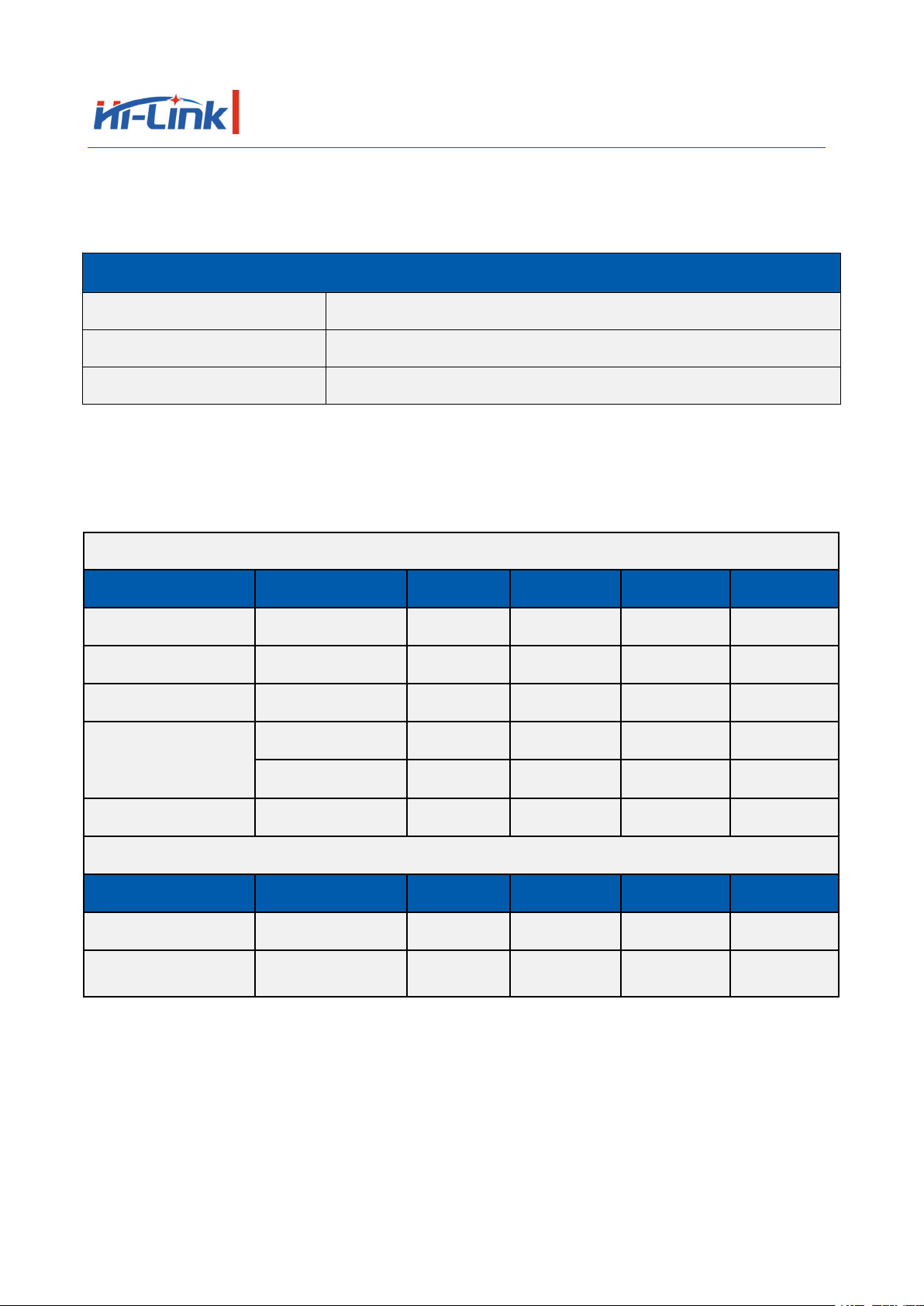
2.2. Specification
Items
Parameter
Remarks
Module type
HLK-7628D
Version V1.2
Chip
MT7628DN
Kernel
MIPS24KEc
Frequency
580MHz
Storage
DDR2 64MB
Flash
16MB
Customized 32MB/8MB
Temperature
Ambient temperature:-40℃~85℃
Humidity
Use: 10~95% (non-condensing)
Storage: 5~95% (non-condensing)
Dimension
18mm×32.8mm×2.8mm
2.3. Interface
Interface
Module interface
Factory default firmware supported interface
WiFi standard
IEEE 802.11b/g/n
Support
Ethernet interface
5 10M/100M adaptive
1 WAN and 4 LAN
UART
3 way
2-way UART with transparent transmission
SDIO
1 way
Unavailable
SPI
1 way
Unavailable
I2C
1 way
Unavailable
I2S
1 way
Unavailable
PWM
1 way
Unavailable
GPIO
Above 8 way
Defined function
Remarks:
1. The module factory default development firmware is written by our company based on Linux; the Ethernet,
WiFi, UART0 and UART1 of the firmware have transparent transmission function.
2. You can rewrite the OPENWRT program or the MTK original Linux program according to the actual use.
Shenzhen Hi-Link Electronic Co., Ltd. Manual
page 5 / 15
HLK-7628D
3. Electrical characteristics
3.1. Power supply requirements
Power supply requirements
Power input voltage
DC:3.3±0.2V
No-load operating current
170±50mA
Supply current requirement
≥800mA
3.2. Radio frequency characteristics
3.2.1. 802.11b 11M
802.11b Transmit (Conductive)
Item
Condition
Min.
Typ.
Max.
Unit
Frequency Range
Channel 1
Channel 13
Tx Power Level
DQPSK
18
20
22
dBm
Frequency Tolerance
-15
0
15
ppm
Spectral Mask
11MHz→22MHz
40
dBr
>22MHz
53
dBr
Modulation Accuracy
All Data Rate
15
%
802.11b Receiver (Conductive)
Item
Condition
Min.
Typ.
Max.
Unit
Frequency Range
Channel 1
Channel 13
Min. Input
11Mbps PER<8%
-91.5
-89.5
-87.5
dBm

Shenzhen Hi-Link Electronic Co., Ltd. Manual
page 6 / 15
HLK-7628D
3.2.2. 802.11g 54M
802.11g Transmit (Conductive)
Item
Condition
Min.
Typ.
Max.
Unit
Frequency Range
Channel 1
Channel 13
Tx Power Level
OFDM
15
17
19
dBm
Frequency Tolerance
-15
0
15
ppm
Modulation Accuracy
All Data Rate
-31
-28
%
802.11g Receiver (Conductive)
Item
Condition
Min.
Typ.
Max.
Unit
Frequency Range
Channel 1
Channel 13
Min. Input
54Mbps PER<10%
-78.0
-76.0
-74.0
dBm
3.2.3. 802.11n MCS7(HT20)
802.11n_HT20 Transmit (Conductive)
Item
Condition
Min.
Typ.
Max.
Unit
Frequency Range
Channel 1
Channel 13
Tx Power Level
OFDM
15
17
19
dBm
Frequency Tolerance
-15
0
15
ppm
Modulation Accuracy
All Data Rate
-31
-28
dB
802.11n_HT20 Receiver (Conductive)
Item
Condition
Min.
Typ.
Max.
Unit
Frequency Range
Channel 1
Channel 13
Min. Input
MCS7 PER<10%
-76.5
-74.5
-72.5
dBm

Shenzhen Hi-Link Electronic Co., Ltd. Manual
page 7 / 15
HLK-7628D
3.2.4. 802.11n_MCS7(HT40)
802.11n_HT40 Transmit (Conductive)
Item
Condition
Min.
Typ.
Max.
Unit
Frequency Range
Channel 1
Channel 13
Tx Power Level
OFDM
15.0
17.0
19.0
dBm
Frequency Tolerance
-15
0
15
ppm
Modulation Accuracy
All Data Rate
-31
-28
dB
802.11n_HT40 Receiver (Conductive)
Item
Condition
Min.
Typ.
Max.
Unit
Frequency Range
Channel 1
Channel 13
Min. Input
MCS7 PER<10%
-76.5
-74.5
-72.5
dBm
4. Module pin definition
4.1. Pin Definition Diagram
HLK-7628D Default pin definition diagram

Shenzhen Hi-Link Electronic Co., Ltd. Manual
page 8 / 15
HLK-7628D
4.2. Default pin function (serial passthrough firmware)
No.
Network name
Type
Function Description
Default features
1
PORST_N
I/O
Module reset (restart), active low
Can't be used to restore the default
settings, hang up without using
2
PERST_N
I/O
PCIe device reset output
Undefined, please hang up, cannot be
pulled up and down
3
REF_CLK0
I/O
Reference clock output
Undefined, please hang up
4
WDT_RST_N
I/O
Watchdog timeout reset
Pull down for 1s and enter the WeChat
AirKiss function;
Pull down for 3s, the serial port exits
transparent transmission and enters AT
mode;
Pull down for 6s, the module restores the
default settings;
5
EPHY_LED4
I/O
PORT4 LED, Active low
LAN4 network port light
6
EPHY_LED3
I/O
PORT3 LED, Active low
LAN3 network port light
7
EPHY_LED2
I/O
PORT2 LED, Active low
LAN2 network port light
8
EPHY_LED1
I/O
PORT1 LED, Active low
LAN1 network port light
9
EPHY_LED0
I/O
PORT0 LED, Active low
WAN network port light
10
WLED_N
I/O
WiFi LED, Active low
WIFI LED flashes when there is a WiFi
signal, can be left floating
11
UART_TXD1
O
Serial port 1 data transmission
Serial port 1 output, hang up without using
12
UART_RXD1
I
Serial port 1 data reception
Serial port 1 input, hang up without using
13
GND
P
Ground
Ground
14
ANT
RF
On-board antenna RF interface,
default external antenna, this pin is
not connected
If you need to connect the foot, you need
to remove the antenna base and replace it
with a 0 ohm resistor.
15
I2S_SDI
I/O
I2S Data input
Undefined, please hang up
16
I2S_SDO
I/O
I2S Data output
Undefined, please hang up, cannot be
pulled up and down
17
I2S_WS
I/O
I2S channel selection,
0: left; 1: right
Undefined, please hang up

Shenzhen Hi-Link Electronic Co., Ltd. Manual
page 9 / 15
HLK-7628D
18
I2S_CLK
I/O
I2S data bit clock
Undefined, please hang up
19
I2C_SCLK
I/O
I2C bus clock
Undefined, please hang up
20
I2C_SD
I/O
I2C bus data
Undefined, please hang up
21
SPI_CS1
I/O
SPI bus chip select signal 1
Undefined, please hang up, cannot be
pulled up and down
22
SPI_CLK
I/O
SPI bus clock signal
Undefined, please hang up, cannot be
pulled up and down
23
SPI_MISO
I/O
SPI bus data master in and slave out
Undefined, please hang up
24
SPI_MOSI
I/O
SPI bus data master out and slave in
Undefined, please hang up, cannot be
pulled up and down
25
SPI_CS0
I/O
SPI bus chip select signal 0
Undefined, please hang up
26
GPIO0
I/O
Universal input and output interface
Undefined, please hang up
27
UART_TXD0
O
Serial port 0 data output
Serial port 0 output, hang up without
using, cannot be pulled up and down
28
UART_RXD0
I
Serial port 0 data input
Serial port 0 input, hang up without using
29
ANT1
RF
On-board antenna RF interface,
default external antenna, this pin is
not connected
If you need to connect the foot, you need
to remove the antenna base and replace it
with a 0 ohm resistor.
30
GND
P
Ground
Ground
31
MDI_RP_P0
I/O
PORT0 Network signal reception
positive
WAN port, hang up without using
32
MDI_RN_P0
I/O
PORT0 Network signal reception
negative
33
MDI_TP_P0
I/O
PORT0 Network signal
transmission positive
34
MDI_TN_P0
I/O
PORT0 Network signal
transmission negative
35
MDI_TP_P1
I/O
PORT1 Network signal
transmission positive
LAN1port, hang up without using
36
MDI_TN_P1
I/O
PORT1 Network signal
transmission negative
37
MDI_RP_P1
I/O
PORT1 Network signal reception
positive

Shenzhen Hi-Link Electronic Co., Ltd. Manual
page 10 / 15
HLK-7628D
38
MDI_RN_P1
I/O
PORT1 Network signal reception
negative
39
MDI_RP_P2
I/O
PORT2 Network signal reception
positive
LAN2 port, hang up without using
40
MDI_RN_P2
I/O
PORT2 Network signal reception
negative
41
MDI_TP_P2
I/O
PORT2 Network signal
transmission positive
42
MDI_TN_P2
I/O
PORT2 Network signal
transmission negative
43
MDI_TP_P3
I/O
PORT3 Network signal
transmission positive
LAN3 port, hang up without using
44
MDI_TN_P3
I/O
PORT3 Network signal
transmission negative
45
MDI_RP_P3
I/O
PORT3 Network signal reception
positive
46
MDI_RN_P3
I/O
PORT3 Network signal reception
negative
47
MDI_RP_P4
I/O
PORT4 Network signal reception
positive
LAN4 port, hang up without using
48
MDI_RN_P4
I/O
PORT4 Network signal reception
negative
49
MDI_TP_P4
I/O
PORT4 Network signal
transmission positive
50
MDI_TN_P4
I/O
PORT4 Network signal
transmission negative
51
USB_DP
I/O
USB Data positive
Undefined, please hang up
52
USB_DM
I/O
USB Data negative
Undefined, please hang up
53
GND
P
Ground
System power
54
3.3VD
P
3.3V input, supply current ≥800mA
55
3.3VD
P
56
GND
P
Ground
Shenzhen Hi-Link Electronic Co., Ltd. Manual
page 11 / 15
HLK-7628D
Remarks:
1. I-input; O-output; I/O-digital I/O; P-power; RF-radio interface. The IO port drives a current of 10mA.
2. The red on the name bar indicates that related to the start of the chip, the external can not be pulled down, can
not be connected to the drive source.
3. The blue color on the remarks column indicates that the default firmware of our factory has this function.
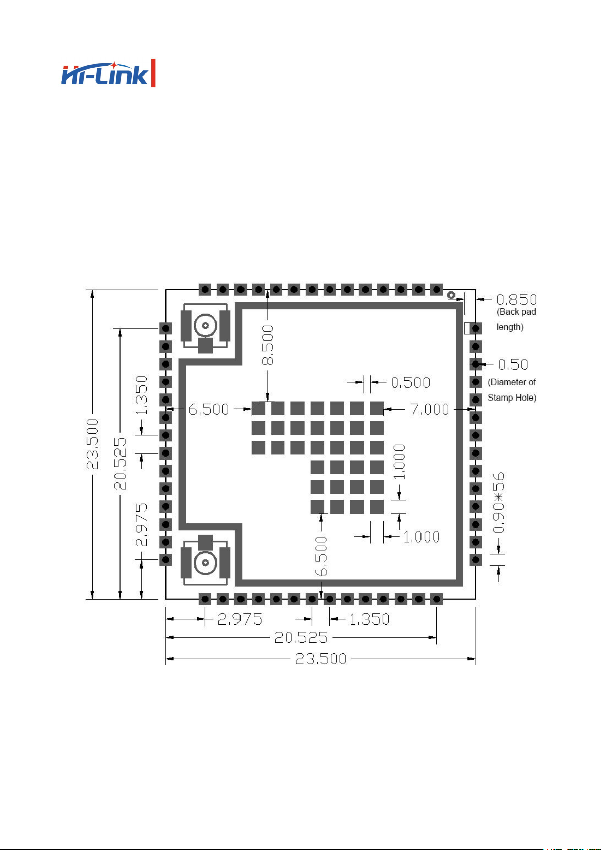
5. Module dimension
Module detailed dimension Unit (mm)
Remarks:
1. The middle pad is a thermal pad and can be grounded.
2. The module pins are symmetrical.
3. The pad size on the diagram is the actual size, please enlarge accordingly when making the package.

Shenzhen Hi-Link Electronic Co., Ltd. Manual
page 12 / 15
HLK-7628D
6. Reflow soldering temperature curve
When the module is over-fired, please strictly follow this temperature curve.
If the temperature deviation of the reflow soldering is too large, the module will be damaged!
Temperature setting (degrees Celsius)
Warm zone
1
2
3
4
5
6
7
8
Upper
temperature zone
125
135
155
185
195
225
240
230
Lower
temperature zone
125
135
155
185
195
225
240
230
Conveyor speed: 70.0 cm/min
Shenzhen Hi-Link Electronic Co., Ltd. Manual
page 13 / 15
HLK-7628D
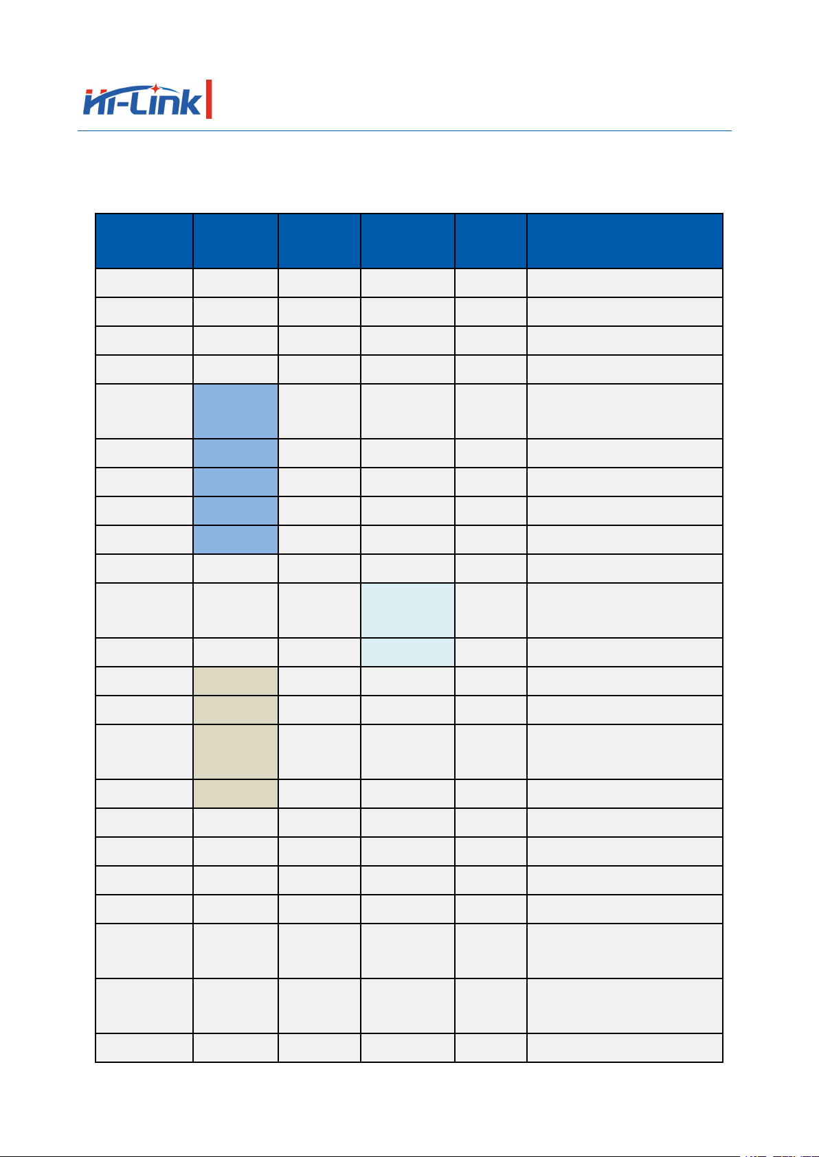
Appendix 1:
Module chip expandable function comparison table (OpenWrt)
Name
(Function 1)
Function 2
Function 3
Function 4
GPIO#
Remarks
SPI_CS0
GPIO#10
SPI bus chip select signal 0
REF_CLK0
GPIO#38
Reference clock output
PERST_N
GPIO#36
PCIe device reset output
WDT_RST_N
GPIO#37
Watchdog timeout reset
EPHY_LED4
JTAG_RST
_N
GPIO#39
PORT4 LED, Active low
EPHY_LED3
JTAG_CLK
GPIO#40
PORT3 LED,Active low
EPHY_LED2
JTAG_TMS
GPIO#41
PORT2 LED, Active low
EPHY_LED1
JTAG_TDI
GPIO#42
PORT1 LED, Active low
EPHY_LED0
JTAG_TDO
GPIO#43
PORT0 LED, Active low
PORST_N
CPU reset, Active low
UART_TXD
1
PWM_CH0
GPIO#45
Serial port 1 data
transmission
UART_RXD1
PWM_CH1
GPIO#46
Serial port 1 data reception
I2S_SDI
PCMDRX
GPIO#0
I2S data input
I2S_SDO
PCMDTX
GPIO#1
I2S data output
I2S_WS
PCMCLK
GPIO#2
I2S channel selection,
0: left; 1: right
I2S_CLK
PCMFS
GPIO#3
I2S data bit clock
I2C_SCLK
GPIO#4
I2C bus clock
I2C_SD
GPIO#5
I2C bus data
SPI_CS1
GPIO#6
SPI bus chip select signal 1
SPI_CLK
GPIO#7
SPI bus clock signal
SPI_MISO
GPIO#9
SPI bus data master in and
slave out
SPI_MOSI
GPIO#8
SPI bus data master out and
slave in
GPIO0
GPIO#11
Universal input and output interface

Shenzhen Hi-Link Electronic Co., Ltd. Manual
page 14 / 15
HLK-7628D
UART_TXD
0
GPIO#12
Serial port 0 data output
UART_RXD0
GPIO#13
Serial port 0 data input
WLED_N
GPIO#44
WiFi LED, active low
MDI_RP_P0
PORT0 Network signal
reception positive
MDI_RN_P0
PORT0 Network signal
reception negative
MDI_TP_P0
PORT0 Network signal
transmission positive
MDI_TN_P0
PORT0 Network signal
transmission negative
MDI_TP_P1
SPIS_CS
PWM_CH0
GPIO#14
PORT1 Network signal
transmission positive
MDI_TN_P1
SPIS_CLK
PWM_CH1
GPIO#15
PORT1 Network signal
transmission negative
MDI_RP_P1
SPIS_MISO
UART_TXD
2
GPIO#16
PORT1 Network signal
reception positive
MDI_RN_P1
SPI_MOSI
UART_RXD
2
GPIO#17
PORT1 Network signal
reception negative
MDI_RP_P2
eMMC_D7
PWM_CH0
GPIO#18
PORT2 Network signal
reception positive
MDI_RN_P2
eMMC_D6
PWM_CH1
GPIO#19
PORT2 Network signal
reception negative
MDI_TP_P2
UART_TX
D2
eMMC_D5
PWM_CH2
GPIO#20
PORT2 Network signal
transmission positive
MDI_TN_P2
UART_RX
D2
eMMC_D4
PWM_CH3
GPIO#21
PORT2 Network signal
transmission negative
MDI_TP_P3
SD_WP
eMMC_WP
GPIO#22
PORT3 Network signal
transmission positive
MDI_TN_P3
SD_CD
eMMC_CD
GPIO#23
PORT3 Network signal
transmission negative
MDI_RP_P3
SD_D1
eMMC_D1
GPIO#24
PORT3 Network signal
reception positive

Shenzhen Hi-Link Electronic Co., Ltd. Manual
page 15 / 15
HLK-7628D
MDI_RN_P3
SD_D0
eMMC_D0
GPIO#25
PORT3 Network signal
reception negative
MDI_RP_P4
SD_CLK
eMMC_CL
K
GPIO#26
PORT4 Network signal
reception positive
MDI_RN_P4
SD_CMD
eMMC_C
MD
GPIO#28
PORT4 Network signal
reception negative
MDI_TP_P4
SD_D3
eMMC_D3
GPIO#29
PORT4 Network signal
transmission positive
MDI_TN_P4
SD_D2
eMMC_D2
GPIO#27
PORT4 Network signal
transmission negative
USB_DP
USB Data positive
USB_DM
USB Data negative
Table of contents
Other Hi-Link Control Unit manuals

Hi-Link
Hi-Link HLK-LD015-5G User manual

Hi-Link
Hi-Link HLK-LD2410 User manual

Hi-Link
Hi-Link HLK-LD2420 User manual

Hi-Link
Hi-Link HLK-B10 User manual

Hi-Link
Hi-Link HLK-RM08K User manual

Hi-Link
Hi-Link HLK-B20 User manual

Hi-Link
Hi-Link HLK-B36 User manual

Hi-Link
Hi-Link HLK-7688A User manual

Hi-Link
Hi-Link HLK-LD2410 User manual

Hi-Link
Hi-Link HLK-RM08S User manual


