Yacht Devices YDTC-13 User manual

User Manual
Digital Thermometer YDTC-13
Digital Barometer YDBC-05
also covers models
YDTC-13R, YDTC-13RT, YDTC-13N, YDTC-13NT
YDBC-05R, YDBC-05RT, YDBC-05N, YDBC-05NT
Software version
1.40
2018

© 2018 Yacht Devices Ltd. Document YDBC05TC13-006. April 20, 2018.
Web: http://www.yachtd.com/
Digital Thermometer and Digital Barometer are certied
by the National Marine Electronics Association.
NMEA 2000® is a registered trademark of the National
Marine Electronics Association. SeaTalk NG is a registered
trademark of Raymarine UK Limited. Garmin®
is a registered trademark of Garmin Ltd.

Contents
Introduction 4
Warranty and Technical Support 6
I. Product Specication 7
II. Device Connection and Testing 9
III. Device Programming and Settings 15
IV. Programming with Installation Description String 19
V. Programming with Datum or Variation 23
VI. LED Signals 30
VII. Firmware Updates 31
Appendix А. Troubleshooting 33
Appendix B. Description of Connectors and Joints 35
Appendix C. NMEA 2000 Messages 36
Package Contents
Device 1 pc.
This Manual 1 pc.

— 4 —
Introduction
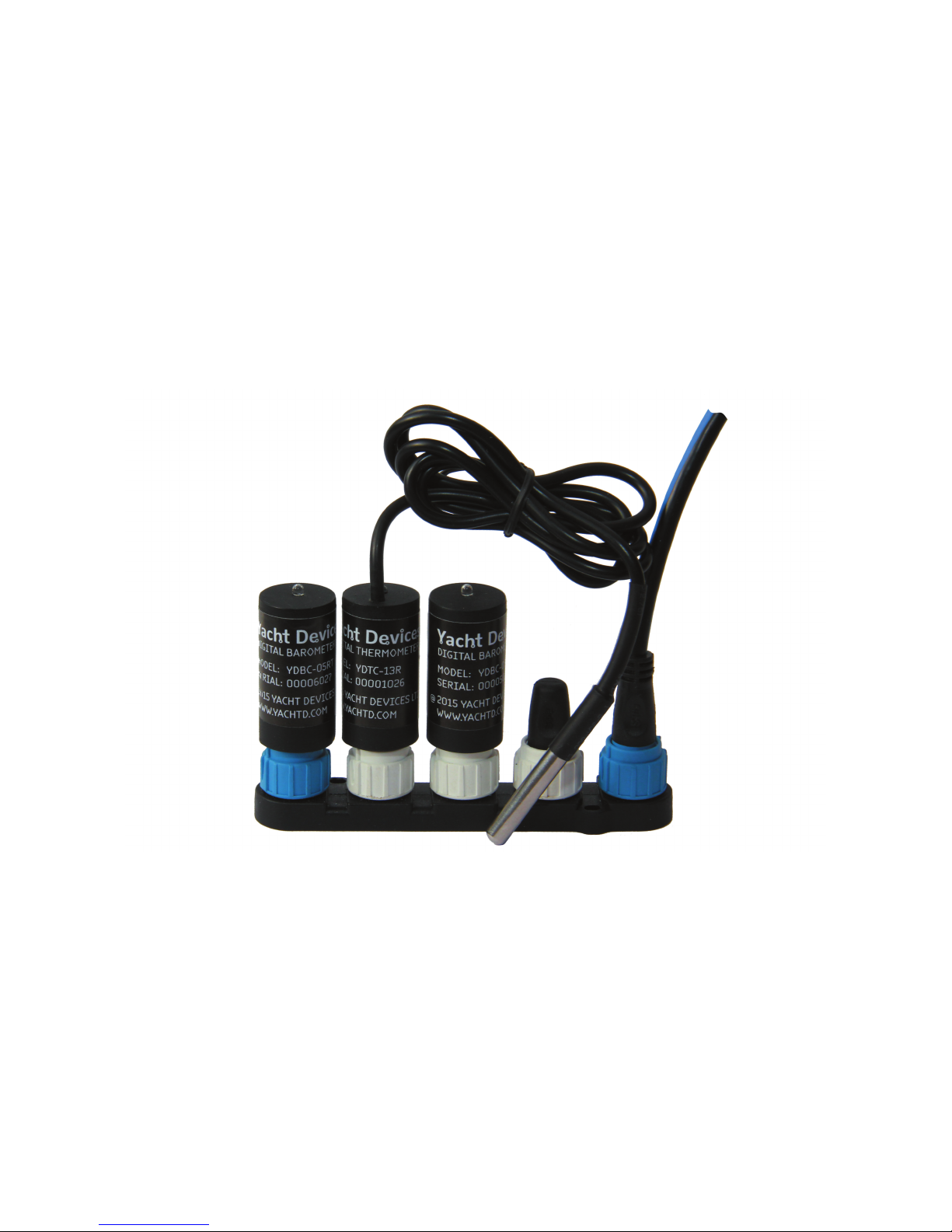
This Manual contains information on how to install, congure and operate YDTC-13
digital thermometers (hereinafter Thermometer) and YDBC-05 digital barometers
(hereinafter Barometer) intended for use on pleasure crafts.
The Thermometer and Barometer (hereinafter, where the differences are not
critical, Devices) have one digital sensor. Up to 50 devices may be used on a vessel
simultaneously; this limitation is set by the network specication. Data from
the Devices can be displayed on chartplotters, digital navigation instruments, as well
as used by other digital equipment of the vessel.
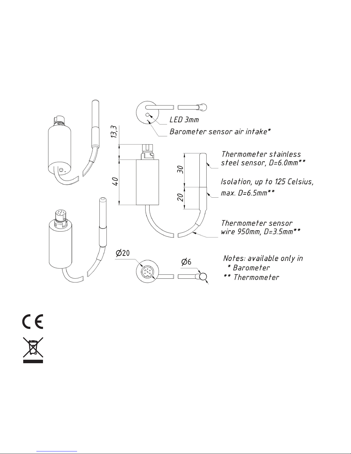
The Thermometer performs measurements within the range from -55 to +125 °С
(-67..+257 °F), the sensor is placed outside the case on a exible 95cm-long wire
in a sealed stainless steel sleeve and can be used to measure the temperature
of gases and liquids. The wire, if necessary, can be elongated up to 100 meters.
The Thermometer can be congured to display its data as "Air temperature",
"Sea temperature", "Temperature in the refrigerator", "Temperature in the engine
room", etc.
The Barometer is intended for measuring atmospheric pressure within the range
from 300 to 1100 hPa (mbar). The sensor is located inside the device case.
The Barometer identier can be congured so that data from several Barometers
will be simultaneously displayed on a chartplotter.
The Devices are designed for operating in an NMEA 2000 network and
are compatible with a wide range of equipment supporting this protocol. Raymarine
SeaTalk NG, Simrad SimNet, Furuno CAN networks are branded versions
of NMEA 2000 and differ only in the type of connectors. In its devices, Garmin
uses the NMEA 2000 Micro connector which is compatible with the DeviceNet

— 5 —
Micro connector. Our Devices are supplied with different types of connectors,
making it possible to connect them to networks of different manufacturers without
any adapters. The Device model is shown on the case.
Device model Type of the connector, compatibility
(see Appendix B)
YDBC-05R, YDTC-13R Raymarine SeaTalk NG Female
YDBC-05RT,
YDTC-13RT Raymarine SeaTalk NG Female Terminator
YDBC-05N, YDTC-13N,
YDBC-05NT, YDTC-13NT
NMEA 2000 Micro Male, DeviceNet Micro Male,
Garmin NMEA 2000 Male
To connect to other types of NMEA 2000 networks, a cable adapter is required
(it is not supplied with the Device and must be purchased separately).
According to the specication, an NMEA 2000 network has two terminators
(120-Ohm resistors) connected to the NMEA 2000 bus ends. Device models with
the T index at the end of their names contain a built-in terminator and should be
connected to the network instead of the terminator. This allows a zero-cost connection
of the Devices to existing networks with no free connectors. Please note that according
to the specication, you can not use more than two devices with the T index on one
NMEA 2000 bus.
We thank you for purchasing our Devices and wish you happy voyages!

— 6 —
Warranty and Technical Support
1. The Device warranty is valid for two years from the date of purchase. If a Device
was purchased in a retail store, when applying under a warranty case, the sale
receipt may be requested.
2. The Device warranty is terminated in case of violating the instructions of this
Manual, case integrity breach, repair or modication of the Device without
manufacturer’s written permission.
3. Modication of the Thermometer sensor cable is performed by the user at his own
risk, the warranty does not cover the Device failure in this case.
4. If a warranty request is accepted, the defective Device must be sent
to the manufacturer.
5. The warranty liabilities include repair and replacement of the goods and do not
include the cost of equipment installation and conguration, as well as shipping
the defective Device to the manufacturer.
6. Responsibility of the manufacturer in case of any damage as a consequence
of the Device operation or installation is limited to the Device cost.
7. The manufacturer is not responsible for any errors and inaccuracies in guides and
instructions of other companies.
8. The Device requires no maintenance. Device’s case is non-dismountable. If the
event of a failure, please refer to Appendix A before contacting the technical
support.
9. The manufacturer accepts applications under the warranty and provides technical
support only via e-mail or from authorized dealers.
10. Contact details of the manufacturer and a list of the authorized dealers
are published on the website: http://www.yachtd.com/.

— 7 —
I. Product Specification
Figure 1. Combined drawing of the Thermometer and Barometer
Yacht Devices Ltd declares that this product is compliant with the essential
requirements of EMC directive 2004/108/EC.
Dispose of this product in accordance with the WEEE Directive. Do not mix
electronic disposal with domestic or industrial refuse.

— 8 —
Device parameter Value Unit
Operating voltage (from an NMEA 2000 network) 7..16 V
Protection against reverse polarity Yes —
Consumption current of the Thermometer / Barometer 24 / 24 mA
Load Equivalency Number 1 LEN
Operating temperature range (except the Thermometer sensor) -40..+80 °С
Weight of the Thermometer / Barometer 31 / 11 g
NMEA 2000 data output resolution 0.01 °С / hPa
Parameters of the Barometer
Measurement range 300..1100 hPa
Relative measurement accuracy ± 0.12 hPa
Absolute measurement accuracy, at 0..+65 °С± 1 hPa
Absolute measurement accuracy in the rest of the range ± 2.5 hPa
Parameters of the Thermometer
Measurement range -55..+125 °С
Error of the thermometer within the range of -10..+85°C, max ± 0.5 °С
Error of the thermometer within the rest of the range, max ± 2 °С

— 9 —
II. Device Connection and Testing
The Device requires no maintenance; calibration of the digital sensors has been
performed by the manufacturer. Therefore, you can set an offset from -10.0 to +10.0
(Celsius for Thermometer or hPa for Barometer) for the sensor readings to align
with readings from other ship equipment (see Section III).
When deciding where to install the Device, choose a dry mounting location.
Avoid places where the Device can be ooded with water, this can damage
it. The Thermometer sensor has a waterproof case made of stainless steel
and is not intended for permanent location in hostile environments such as sea
water. To prevent corrosion, when installing outdoors protect the sensor case with
the help of a coating of paint.
Read the model number on the Device case. If the model name has the T index
at the end (for example, YDBC-05NT), then the device has a built-in terminator
(with resistance of 120 Ohm) and must be connected to the bus instead of an existing
terminator. Different connectors for terminators (blue) and devices (white) are used
in the SeaTalk NG network, which eliminates the chance to err. In networks with
the NMEA 2000 Micro connectors (DeviceNet Micro, Garmin NMEA 2000), devices
are connected to the Female connector on the bus, while terminators are connected
to both Male and Female connectors.
The Device is directly connected to the bus without a drop cable. Before connecting
the Device, turn off the bus power supply. Refer to the manufacturer's documentation
if you have any questions regarding the use of connecting cables, terminators
and connectors:

— 10 —
• SeaTalk NG Reference Manual (81300-1) for Raymarine networks
• Technical Reference for Garmin NMEA 2000 Products (190-00891-00)
for Garmin networks
After connecting the Device, close the lock on the connection to ensure its water
resistance and reliability.
Figure 1. SeaTalk NG bus with the YDBC-05RT, YDTC-13R and
YDBC-05R (left to right)
After turning on the bus power supply, the Device LED will produce one or two short

— 11 —
signals every second (see LED signals in Section VI).
If the Device is connected to a network having a chartplotter or any other device
transmitting a PGN 0x1F814 (129044) message with chart datum conguration
or PGN 0x1F11A (127258) with data on magnetic variation, the Device will produce
six LED signals with a period of 0.5 seconds when such message is received
for the rst time after power is on. This usually happens within 15 seconds after
the Device is turned on. The signal series conrms the Device is properly connected
to the NMEA 2000 network and the chartplotter is able to receive data from
the Device.
The Device information should be displayed in the list of NMEA 2000 devices
(SeaTalk NG, SimNet, Furuno CAN) or in the common list of external devices
on the chartplotter (see Figure 2). Usually, access to this list is in the "Diagnostics",
"External Interfaces" or "External devices" menu.
Data from the Device are available to all the equipment connected to the network
and can be displayed simultaneously on several chartplotters and digital navigation
instruments.
Under the factory settings, the Thermometer shows measured data as air temperature.
The Barometer always shows the measured data as atmospheric pressure, regardless
of the user’s settings.
Switch to the chartplotter screen, which provides information about the atmospheric
pressure (for the Barometer) and air temperature (for the Thermometer) or add this
indicator to the screen using instructions supplied with your equipment. Data in the
indicator should begin to appear no later than 5 seconds after turning the Device on.
Data is updated at an interval of 500 milliseconds.
Many chartplotters and digital navigation instruments are able to display data

— 12 —
on pressure and temperature in the form of graphs; this allows tracking of trends
in the weather. The digital indicator can also contain a trend pointer (see Figure 3).
The Thermometer can be reprogrammed by the user to display data in other indicators,
such as «Sea temperature», «Temperature in the engine room», «Temperature
in the refrigerator» (see Section III).
Figure 2. Raymarine c125 MFD devices list with Barometer and Thermometer

— 13 —
Figure 3. Garmin GPSmap 721 display with the connected Barometer
and two Thermometers
The Thermometer sensor cable can be elongated up to 100 m by the user himself
(note that the warranty for the modied Device is not maintained). To do this,
turn the Device off, cut the cable in the middle (see Appendix B) and extend
it with a three-conductor wire and properly insulate the joints. The wires
are recommended to be connected by crimping in sleeves rather than soldering.
Soldered connections can quickly break down in the marine environment.

— 14 —
The core section of the connection cable must not be less than 0.2 sq. mm, with
the diameter of 0.5 mm. Cables of UTP 3, UTP 5, UTP 5e categories with the AWG-24
and AWG-22 labelling used for telephone lines and computer networks are suitable
for the role of a connection cable. When routing the cable, avoid powerful sources
of electromagnetic interference: motors, compressors, generators, electric pumps
and transmitting antennas.
If after the cable extension the Thermometer’s LED shines for two seconds with
small interruptions, this indicates absence of communication with the digital sensor
(see. Appendix A. Troubleshooting). In this case, check the connection cable
and joints. Note that in previous rmware versions (1.2x and 1.3x), Thermometer
shows a temperature of 290 °C in case of communication error; this behavior
was modied.

— 15 —
III. Device Programming and Settings
Programming of the Device should not be performed at sea.
The Device can be programmed by three methods. Table 1 on the next page shows
the applicability of the methods for different settings. The following methods are
supported:
1. By a special sequence of datum or variation settings on a chart plotter (column
[1] at Table 1). This method is tricky, but it only requires a chart plotter
and it can be performed on legacy chart plotters. Tested with Garmin
and Raymarine chart plotters. See Section V for details.
2. With a special installation description string which can be entered
for the Device in PC software like CAN Log Viewer from our company, ActiSense
NMEA Reader or Maretron N2KAnayzer. This method is very simple and may
be supported in some models of chart plotters. Described in the next Section.
3. Using special PC software, including professional NMEA 2000 installer
software. The Device supports «Request Message», «Command Message»
and «Write Fields» functions of PGN 126208, which allows changing
of the Device settings.

— 16 —
Table 1. Applicability of the programming methods
Number Setting or action Method
[1] [2] [3]
(1) NMEA 2000 device instance and system
instance Yes Yes Yes
(2) NMEA 2000 data instance Yes Yes Yes
(3) Type of a measured data (Thermometer
only) Yes Yes Yes
(4) Transmission interval for periodic messages Note 1 Yes Yes
(5) Sensor reading offset No Yes Note 3
(6) Installation description No Yes Yes
(7) Reset all settings to factory values Yes Yes Note 3
(8) NMEA 2000 message priority No No Note 2
Note (1): Only turning on with default transmission interval and off are
allowed with this method.
Note (2): Setting is not stored in non-volatile memory and acts only while
Device is powered.
Note (3): Not allowed with «Command Message» and «Write Fields» of PGN
126208, use method 2.
NMEA 2000 device and system instances (1) should not be modied by a user,
these elds are used by installers in complex NMEA 2000 networks. Message priority
(8) can be dynamically managed on the network by devices and is not intended
to be managed by a user.

— 17 —
NMEA 2000 data instance (2) may be used when multiple Devices are installed.
For example, data on the refrigerator temperature with instance 3 can be displayed
as “Temperature in refrigerator № 3”. Chart plotters with factory settings are usually
able to show only one value with data instance 0, but manufacturers may supply
dealers and professional installers by internal instruments to customize chart plotter
screens. Please refer to your chart plotter manual before changing this setting.
You can choose one of the 14 types of data types (3) for the Thermometer. Note that,
for example, data on the engine room temperature (value 3 in Table 2) cannot be send
in the PGN 130310. Refer to your chart plotter or instrument display manual what
PGNs and temperature types are supported.
The data transmission interval (4) setting allows changing of the interval of periodical
(data transmitting) messages with methods [2] or [3] and individually turning on/off
message transmission with all three methods. Intervals from 50 milliseconds (value
50) to 1 hour (value 3600000) are allowed, a value of 0 turns off the transmission
(but data can be received by request). “Restore default Interval” value is also supported
in method [3] (see Appendix C). In case of method [1], the user can only turn on
and off transmission of messages.
The Device sensor is calibrated at the factory. Therefore, you can set an offset (5) from
-10.0 to +10.0 (Celsius for Thermometer, hPa for Barometer) for the sensor readings
to align with readings from other ship equipment.
Installation description (6) are two text elds (see the next Section), which can be
lled in by installer to specify the Device’s location or leave notes and contact data.
Special strings starting with “YD:” in the second eld are used for Device programming
in method [2].
Resetting of settings (7) returns a Device to the factory state.

— 18 —
The next two Sections describe the details of Device programming with methods [2]
and [1]. Regarding method [3], please refer to your software manual and the NMEA
2000 Standard.
Table 2. Setting type of a measured data for the Thermometer
Type
setting Description NMEA 2000 messages, PGN
130310 130311 130312 130316
0 Sea Temperature Yes Yes Yes Yes
1* Outside Temperature Yes Yes Yes Yes
2 Inside Temperature — Yes Yes Yes
3 Engine Room Temperature — Yes Yes Yes
4 Main Cabin Temperature — Yes Yes Yes
5 Live Well Temperature — — Yes Yes
6 Bait Well Temperature — — Yes Yes
7 Refrigeration Temperature — — Yes Yes
8 Heating System Temperature — — Yes Yes
9 Dew Point Temperature — — Yes Yes
10 Wind Chill Temperature, Apparent — — Yes Yes
11 Wind Chill Temperature, Theoretical — — Yes Yes
12 Heat Index Temperature — — Yes Yes
13 Freezer Temperature — — Yes Yes
* — Factory setting

— 19 —
IV. Programming with Installation Description String
This method is not available for Devices with the rmware version below
1.40.
Installation description strings are usually written by installers to specify the device
location or to leave notes or contact information. This can be done with professional
PC software (with a hardware connector to NMEA 2000 network) and it may be
supported by some models of chart plotters. Please refer to your software or chart
plotter documentation for details.
To program the Device, enter a special string starting with “YD:” to the installation
description eld 2 in the Device properties. For example, “YD:DEV 1” (without quotes)
will change the NMEA 2000 device instance of the Device to 1. If the command
is accepted by the Device, it will add “ DONE” to the entered text
and “YD:DEV 1 DONE” will be displayed in the case of our example. Note that
the Device always accepts correct strings regardless of the current settings, etc.
In Figure 1 on the next page, you can see the process of programming the Device with
free CAN Log Viewer software (to open this window, select the item «NMEA 2000
Devices» in the «View» menu, refresh the list of devices, select the device and click
«Properties» button). You can download this program (runs on Microsoft Windows,
Mac OS X and Linux) at http://www.yachtd.com/downloads/, Yacht Devices NMEA
2000 Wi-Fi Gateway or Yacht Devices NMEA 2000 USB Gateway is required
to connect the PC with NMEA 2000 network.
In the software you can also modify the NMEA 2000 device instance by entering
a value in the dedicated eld (see «Address Claim» group on the screenshot).
After entering the command as shown in Figure 1 (click «Update» button to apply

— 20 —
changes), the value in the «Device Instance» eld will be changed to 1, and “Installation
Details 2” eld will be changed to “YD:DEV 1 DONE”.
After entering the command as shown in Figure 1 (click «Update» button to apply
changes), the value in the «Device Instance» eld will be changed to 1, and “Installation
Details 2” eld will be changed to “YD:DEV 1 DONE”.
Figure 1. Programming with CAN Log Viewer
Other manuals for YDTC-13
1
This manual suits for next models
9
Table of contents
Other Yacht Devices Marine Equipment manuals
Popular Marine Equipment manuals by other brands

Teledyne
Teledyne STREAMPRO Guide

KVH Industries
KVH Industries TracPhone V7-HTS quick start guide

MOFLASH SIGNALLING
MOFLASH SIGNALLING SB150-1 Series INSTALLATION & TECHNICAL INFORMATION

Simrad
Simrad Navico WP10 manual

ACR Electronics
ACR Electronics Nauticast 2607 user manual

Kohler
Kohler GM93516-KP1 installation instructions