Hi-Target V500 User manual

V500 GNSS RTK System
User Manual
V500 GNSS System User Manual
Revision Date Revision Level Description
June. 2023 1 V500 GNSS RTK System
User Manual

V500 GNSS System User Manual
V500
GNSS RTK System
User Manual
V500 GNSS System User Manual
I
Preface
Introduction
Welcome to the Hi-Target V500 GNSS receiver. This introduction describes how to use this product.
Experience requirement
To help you use the Hi-Target series products better, Hi-Target suggests that you read the instructions
carefully. If you are unfamiliar with the products, please refer to www.hi-target.com.cn
Tips for safe use
Notice: The contents here are special operations and need your special
attention. Please read them carefully.
Warning: The contents here are generally very important as the wrong
operation may damage the machine. This can lead to the loss of data, or even
break the system and endanger your safety.
Exclusions
Before using the product, please read these operating instructions carefully, as they will help you to use
it better. Hi-Target Surveying Instrument Co. Ltd assumes no responsibility if you fail to operate the
product according to the instructions, or operate it wrongly because you have misunderstood them.
Hi-Target is committed to constantly perfecting the product’s functions and performance, improving its
service quality, and reserves the right to change these operating instructions without notice.
We have checked the contents of the instructions and the software & hardware without eliminating the
possibility of deviation. The pictures in the operating instructions are for reference only. In the case of
non-conformity with products, the products shall prevail.
V500 GNSS System User Manual
II
Technology and service
If you have any technical issues, please call the Hi-Target technology department for help, and we will
answer your question.
Relevant information
You can obtain this introduction by:
Purchasing Hi-Target products: this manual is found in the instrument container and will help you to
operate the instrument.
Logging on to the Hi-Target official website and downloading the electronic version of this introduction
from Partner Center:http://members.hi-target.com.cn/
Advice
If you have any suggestions for this product, please email them to: sales@hi-target.com.cn. Your
feedback information will help us to improve the product and service.
V500 GNSS System User Manual
III
Contents
Preface.....................................................................................................................................................................I
Introduction..........................................................................................................................................................I
Experience requirement.....................................................................................................................................I
Tips for safe use..................................................................................................................................................I
Exclusions............................................................................................................................................................I
Technology and service....................................................................................................................................II
Relevant information .........................................................................................................................................II
Advice..................................................................................................................................................................II
Contents ..................................................................................................................................................................III
Chapter 1................................................................................................................................................................1
Overview................................................................................................................................................1
1.1 Foreword.......................................................................................................................................................2
1.2 Features........................................................................................................................................................2
1.3 Use and precautions...................................................................................................................................2
Chapter 2................................................................................................................................................................4
Product introduction.......................................................................................................................................4
2.1 Overall appearance.....................................................................................................................................5
2.1.1 Upper cover..........................................................................................................................................5
2.1.2 Bottom cover.........................................................................................................................................5
2.1.3 Control cover........................................................................................................................................6
2.2 Button & LED...............................................................................................................................................7
2.2.1 Button function .....................................................................................................................................7
2.2.2 LED........................................................................................................................................................7
2.3 WEB management system........................................................................................................................8
2.3.1 Main menu............................................................................................................................................8
2.3.2 Information......................................................................................................................................... 11
2.3.3 Work Mode......................................................................................................................................... 14
2.3.4 File manager...................................................................................................................................... 15
2.3.5 Firmware ............................................................................................................................................ 16
2.3.6 System................................................................................................................................................ 17
2.3.7 Coordinate system............................................................................................................................ 19

V500 GNSS System User Manual
IV
2.4 Static survey.............................................................................................................................................. 21
2.4.1 Static settings.................................................................................................................................... 21
2.4.2 Static data collection steps.............................................................................................................. 21
2.4.3 Static data download........................................................................................................................ 22
2.5 Tilt survey.................................................................................................................................................. 24
2.5.1 Calibration-free tilt survey................................................................................................................ 24
2.6 Firmware upgrade.................................................................................................................................... 25
2.6.1 Upgrade by USB cable..................................................................................................................... 25
2.6.2 Upgrade by using the web management system......................................................................... 26
2.7 AR Stakeout ................................................................................................................................................. 26
2.7.1 AR Stakeout Instructions ...................................................................................................................... 26
Chapter 3............................................................................................................................................................. 28
Technical specification ...................................................................................................................................... 28
3.1 Technical parameters.............................................................................................................................. 29
Chapter 4............................................................................................................................................................. 32
Accessories and interfaces ................................................................................................................................ 32
4.1 Data cable................................................................................................................................................. 33
4.2 Antenna...................................................................................................................................................... 33
4.3 Battery........................................................................................................................................................ 33

V500 GNSS System User Manual
1
Chapter 1
Overview
This chapter contains:
- Foreword
- Features
- Use and precautions

V500 GNSS System User Manual
2
1.1 Foreword
V500 GNSS receiver brings superior performance and high efficiency that will support your fieldwork
with reliable solutions. Equipped with an upgraded high-definition starlight camera, V500 brings out an
excellent visual stakeout experience in low-light conditions. The compact and lightweight design makes
V500 a feasible and portable choice for engineering personnel in collecting data and improving
positional accuracy.
1.2 Features
1. With an ultra-light EPP material instrument case it is more durable and portable.
2. A lower camera is used for AR stakeout with an accuracy of better than 1 cm.
3. The inclusion of a high-performance patch antenna both enhances the low elevation angle tracking
capabilities and maintains a high gain for higher elevation satellites.
4. It can bring accurate and reliable results and boost efficient fieldwork with a self-developed built-in
IMU and core algorithm.
5. Hi-Fix technology enables both continuous connectivity and quality results as a certain level of
accuracy continues to be guaranteed even in the absence of differentials.
1.3 Use and precautions
The V500 GNSS receiver is designed to havechemicaland impactresistance, but precision instruments
require careful use and maintenance.
In order to ensure the continuous tracking observation of the satellite and quality of the satellite signal,
the space above the station should be as wide as possible, with no obstacles above the 15°elevation
angle. To reduce the interference of various electromagnetic waves on the GNSS satellite signal, there
should be no strong electromagnetic interference within a range of about 200m around the station, such
as TV towers, microwave stations, and high-voltage transmission lines. To avoid or reduce the
Notice: The receiver must be within the specified temperature range when it
is used and stored. For detailed requirements, please refer to Chapter 3:
Technical specification.

V500 GNSS System User Manual
3
occurrence of multipath effects, the station should be away from terrain and features with strong
reflectors, such as high-rise buildings, water, etc.

V500 GNSS System User Manual
4
Chapter 2
Product introduction
This chapter contains:
- Overall appearance
- Button & LED
- WEB management system
- Static survey
- Tilt survey
- Firmware upgrade
- AR Stakeout
V500 GNSS System User Manual
5
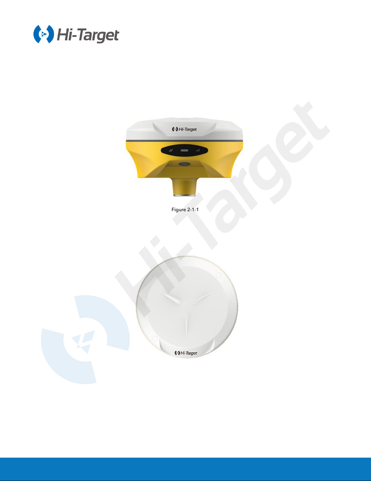
2.1 Overall appearance
The product’s appearance is divided into three parts, the upper cover, bottom cover and control panel.
Figure 2-1-1
2.1.1 Upper cover
Figure 2-1-2
2.1.2 Bottom cover
The bottom cover includes the SMA antenna interface, Type-C USB interface.

V500 GNSS System User Manual
6
Figure 2-1-3
1. Power button 2. Speaker 3. Connection screw
4. Camera 5. Type-C USB interface 6. SMA antenna interface
◇SMA antenna interface: Connect the radio antenna while using the Internal UHF mode.
◇Type-C USB interface: To upgrade the firmware and download static data.
◇Protective plug: Used for dustproof and waterproof sockets.
2.1.3 Control cover
The control panel includes a satellite light, power button and data light.
Figure 2-1-4
Notice:
1. If you don’t use the SMA antenna interface and USB interface, please cover
the rubber plug to protect them from dust and water.
2. When the speaker is flooded, the sound may be silent or hoarse, but it will
return to normal after it has dried.
6
4
3
5
1 2
3
2 1
V500 GNSS System User Manual
7
1. Satellite LED 2. Data LED 3. Power LED
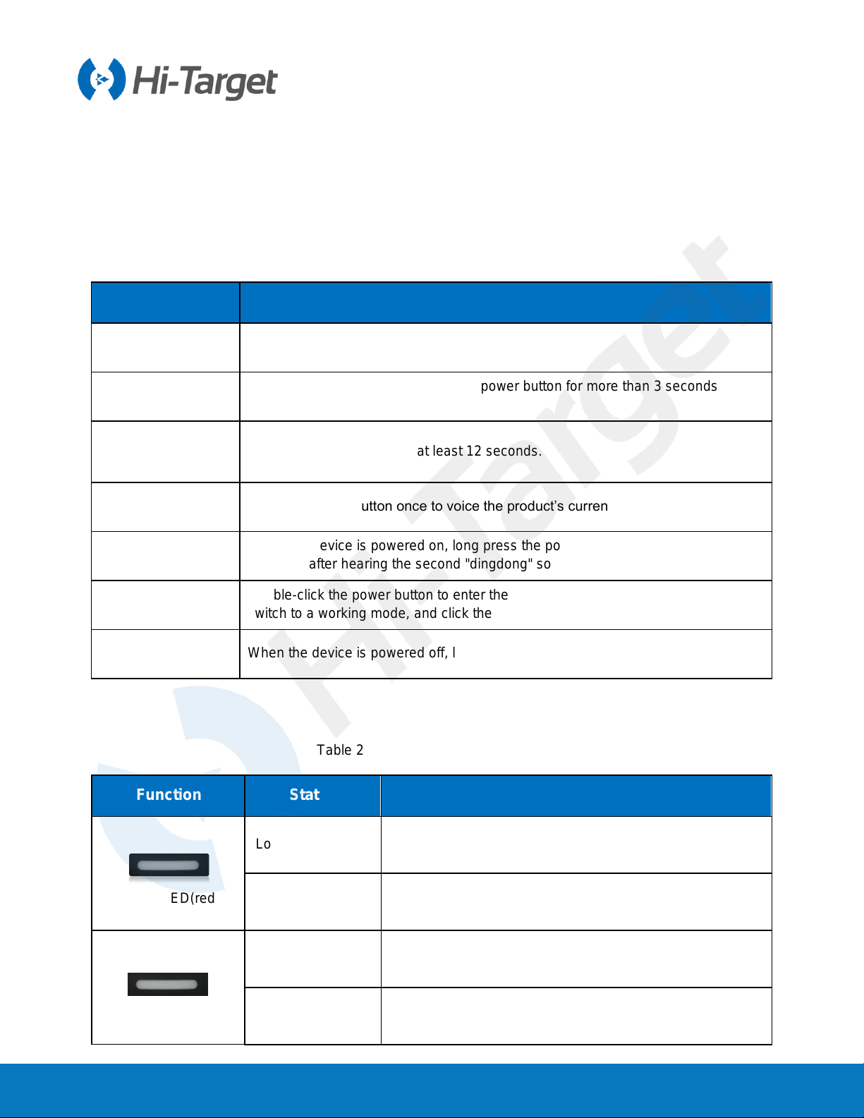
2.2 Button & LED
2.2.1 Button function
Table 2-2-1 Button function description
Function Description
Power-on Long press the power button for 1 second.
Power-off In the power-on state, long press the power button for more than 3 seconds but
less than 6 seconds.
Forced shutdown
(use when the
device crashes)Press the power button for at least 12 seconds.
Query current
status Press the power button once to voice the product’s current working status.
Reset motherboard When the device is powered on, long press the power button for 6 seconds and
release it after hearing the second "dingdong" sound.
Switch working
mode Double-click the power button to enter the mode switch. After each double-click,
switch to a working mode, and click the power button to confirm it.
One-key setting
station When the device is powered off, long press the power button for 6s to turn it on.
2.2.2 LED
Table 2-2-2 LED function description
Function Status Description
Power LED(red)
Long-term lighting When the device is powered off, it is for charging the device.
OFF It is not charging or fully charged.
Power LED(green)
Flash The power ≤10%.
Long-term lighting 1. RTK mode: No correction data.
2. Static mode: Sampling has not started.

V500 GNSS System User Manual
8
Data LED Flash
1. RTK mode:
Flashes at the frequency of the correction transmit and
receives.
2. Static mode:
Sampling interval >1s: Flashes at the sampling interval.
Sampling interval ≤1s: Flashes once per second.
Off 1. RTK mode: No correction data.
2. Static mode: Sampling has not started.
Satellite LED
Long-term lighting Satellite is tracked.
Flash Satellite is not tracked.
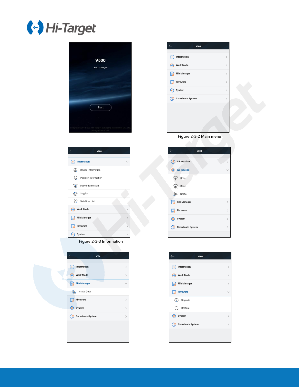
2.3 WEB management system
V500 has a built-in web management system that can be used to set the receiver's working mode,
data output, as well as view receiver information and satellite information. The receiver’s Wi-Fi name
is its S/N. You can connect it to a controller or phone (the default password is: 12345678) and then
input the IP address 192.168.20.1 into the browser to log onto the web management system.
Note: The web management system can only be visited when the receiver’s Bluetooth isn’t connected.
2.3.1 Main menu
After logging into the web management system, you can click Start to enter the main menu interface.
Each option of the main menu contains drop-down menus.
V500 GNSS System User Manual
9
Figure 2-3-1 Home Figure 2-3-2 Main menu
Figure 2-3-3 Information Figure 2-3-4 Work mode
Figure 2-3-5 File manager Figure 2-3-6 Firmware
V500 GNSS System User Manual
10
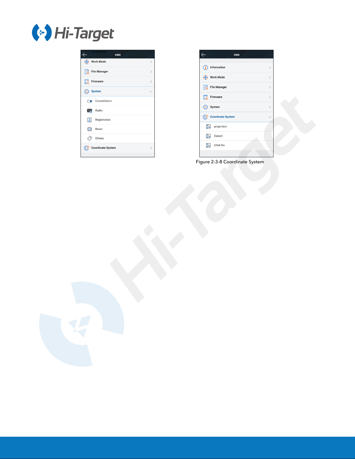
Figure 2-3-7 System Figure 2-3-8 Coordinate System
V500 GNSS System User Manual
11
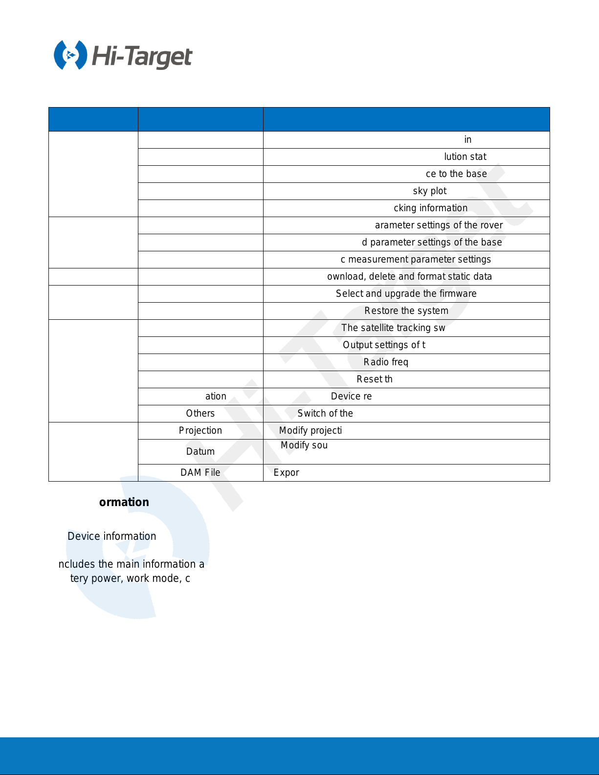
Table 2-3-1 Menu description
Main menu Sub-menu Description
Information
Device info Device model, version, registration info, etc.
Position info Coordinates, satellite tracking, solution state, etc.
Base info Coordinates and distance to the base
Sky plot Check the sky plot
Satellites list Satellite tracking information
Work mode
Rover Data link and parameter settings of the rover
Base Data link and parameter settings of the base
Static Static measurement parameter settings
File manager Static data Download, delete and format static data
Firmware Upgrade Select and upgrade the firmware
Restore Restore the system
System
Constellation The satellite tracking switches
Five-pin port Output settings of the five-pin
Radio Radio frequency list
Reset Reset the motherboard
Registration Device registration and information
Others Switch of the static RINEX and volume control, etc
Coordinate
System
Projection Modify projection model, central meridian, scale factor, etc.
Datum Modify source ellipsoid, target ellipsoid and transformation
model
DAM File Export/import of coordinate system parameters in dam format
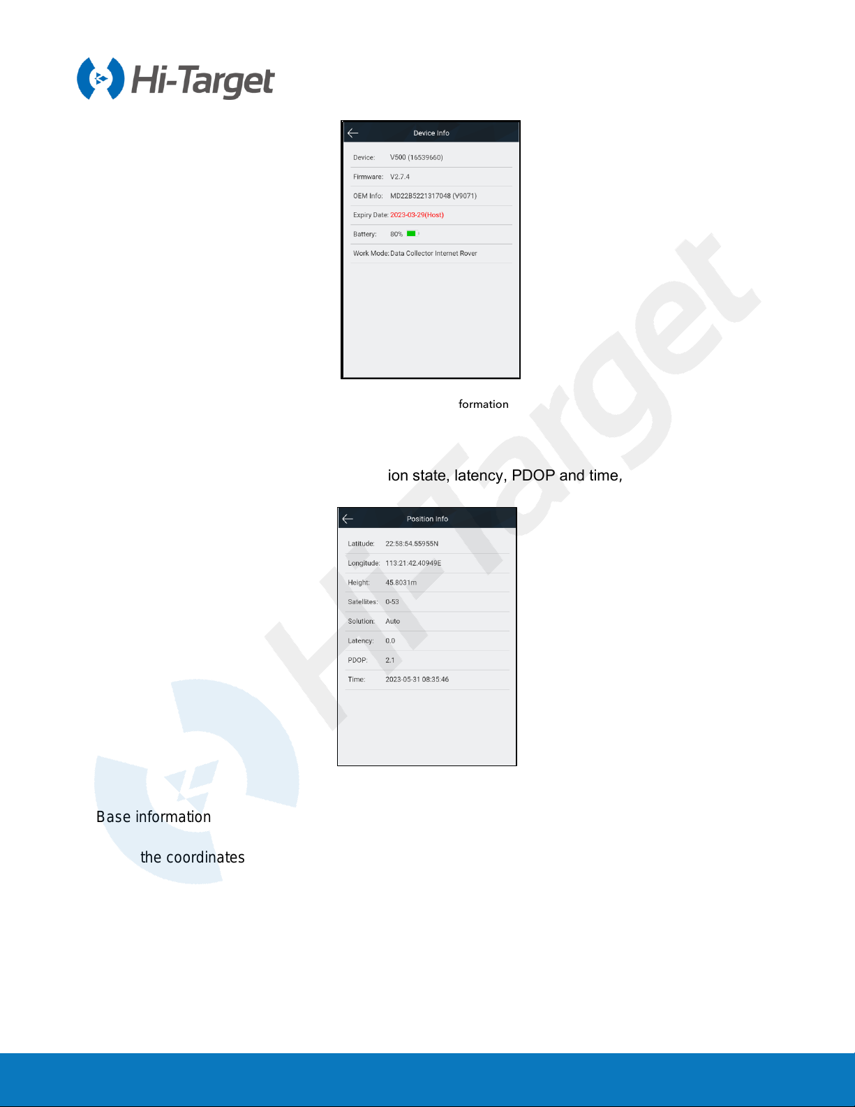
2.3.2 Information
1. Device information
Includes the main information about the device: device model, S/N, firmware version, OEM info,
battery power, work mode, configuration parameters, etc.
V500 GNSS System User Manual
12
Figure 2-3-9 Device information
2. Position information
Includes the device’s position, satellites, solution state, latency, PDOP and time, etc.
Figure 2-3-10 Position information
3. Base information
Includes the coordinates and distance of the base in the rover mode.

V500 GNSS System User Manual
13
Figure 2-3-11 Base information
4. Sky plot
Displays the visual satellites of the device and the switches of each constellation.
Figure 2-3-12 Sky plot
5. Satellites list
Shows the satellite’s tracked information.
Table of contents
Other Hi-Target Boating Equipment manuals

Popular Boating Equipment manuals by other brands

Harken
Harken FlatWinder 250 Installation and maintenance manual

DAVIS
DAVIS Mark 3 manual

Vetus
Vetus PL Series Operation manual and installation instructions

Ultraflex
Ultraflex UC 130 Installation and maintenance manual

Attwood
Attwood 4201 installation instructions

Grammer
Grammer AVENTO MSG 65/511 Repair manual


