Hi-Target iBoat BS2 User manual

BS2 USV User Manual
iBoat BS2 User Manual
Hi-Target Surveying Instrument Co., Ltd.
All Rights Reserved

BS2 USV User Manual
II
Manual Revision
Revision Date
Revision Level
Description
Nov., 2018
2
iBoat BS2 User Manual 1.1 Version
BS2 USV User Manual
III
Preface
Introduction
Thank you for using the Hi-Target iBoat BS2 USV system. This introduction describes how to
use the iBoat BS2 USV system
Experience Requirement
In order to help you use the Hi-Target iBoat BS2 USV system better, we suggest you carefully
read the instructions. If you are unfamiliar with it, please refer to http://www.hi-target.com.cn/
Tips for Safe Use
Notice: The contents here are special operations and need your special attention.
Please read them carefully.
Warning: The contents here are very important. Wrong operation may damage
the machine, lose data, break the system and endanger your safety.
Exclusions
Before using the product, please read these operating instructions carefully, they will help you
to use it better. Hi-Target assumes no responsibility if you fail to operate the product according
to the instructions, or operate it wrongly, due to misunderstanding the instructions.
Hi-Target is committed to constantly perfecting product functions and performance, improving
service quality and we reserve the right to change these operating instructions without notice.
We have checked the contents of the instructions, the software and hardware, without eliminating
the possibility of error. The pictures in the operating instructions are for reference only. In case
of non-conformity with products, the products shall prevail.
Technical Support and Service
If you have any technical issues, please call Hi-Target’s technology department for help.
Relevant Information
You can obtain this introduction by:
1. Purchasing Hi-Target products: you will find this manual in the instrument container to guide
you on operating the instrument.
2. Logging onto the Hi-Target official website, downloading the electronic version introduction
at Partners → Partner center.

BS2 USV User Manual
IV
Advice
If you have any comments and suggestions for this product, please email [email protected].
Your feedback will help us to improve the product and service.

BS2 USV User Manual
V
Contents
Preface.........................................................................................................................III
Hardware Connection..................................................................................................3
Overall Operation Flow..............................................................................................11
2.1 Power on Controller ...................................................................................11
2.2 Switch on USV ............................................................................................11
2.3 LAN IP Setting.............................................................................................11
2.4 Run Virtual Serial Port Software ...............................................................12
2.5 Setup GNSS Receiver by Hi-MAX .............................................................12
2.5.1 New Project ........................................................................................13
2.5.2 Serial Port Debug ...............................................................................14
2.5.3 Equipment Connection .......................................................................19
2.6 USV Ground Control Software (USV GCS) ..............................................20
2.7 Preparation for Surveying .........................................................................27
2.7.1 Coordinate Parameters Configuration................................................27
2.7.2 Boat Shape Design ............................................................................28
2.7.3 Draft Setting .......................................................................................28
2.8 Launch the Boat .........................................................................................29
2.9 Surveying ....................................................................................................30
2.10 Stop the Recording ..................................................................................31
2.11 Retrieve Boat ............................................................................................31
2.12 Data Post-processing ..............................................................................31
2.12.1 Sampling ..........................................................................................31
2.12.2 Data Correction ................................................................................33
2.12.3 Results View.....................................................................................39

BS2 USV User Manual
2
The iBoat series intelligent USV can autopilot by setting waypoints with
GNSS navigation. More sensor equipment can be loaded to perform various
surveying tasks.
Accurate control of iBoat BS2 makes it easy to conduct ultra shallow and
nearshore hydrographic survey, greatly improving the monitoring efficiency
and accuracy, reducing the risk of monitoring staff working on water; And
lightweight easy to carry.
Professional hull design, high-performance sounding module, high-precision
positioning system, USV control software and data processing software are
independently designed and developed by Hi-Target. High integration,
outstanding overall performance, coupled with a sound after-sales service
system, can provide one-stop services.
BS2 USV User Manual
3
Hardware Connection
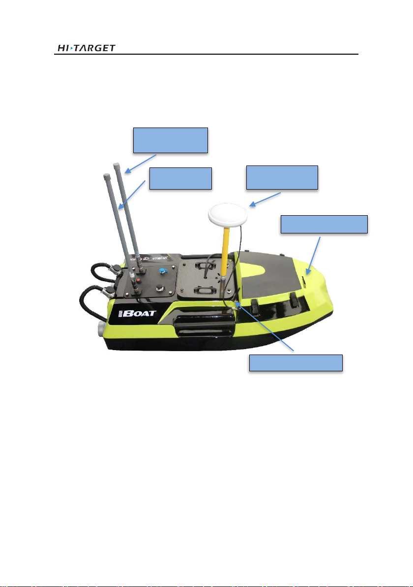
The complete view after all things are installed well:
Figure 1-1 Complete view & antenna description
High-Gain Dual
Frequency Antenna
RTK Radio Antenna Port
Controller
Antenna(2.4GHz)
Data Transmission
Antenna(900MHz)
Differential Antenna
Cellular Internet Antenna
BS2 USV User Manual
4
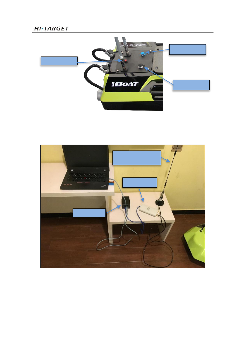
Figure 1-2 Port description
Description of ashore station
Figure 1-3 Ashore Base System
Two network cables are needed. One is used for connecting the black battery and laptop (LAN
Port ↔ laptop ethernet port), working as a LAN cable. While another connects the black battery
(it is also a POE supplier) and the wireless bridge (POE Port ↔ Wireless bridge Ethernet port)
Power Switch
Charging Port
ADCP Port
Wireless Bridge
Ashore Station
omni-direction Antenna
Base Battery
BS2 USV User Manual
5
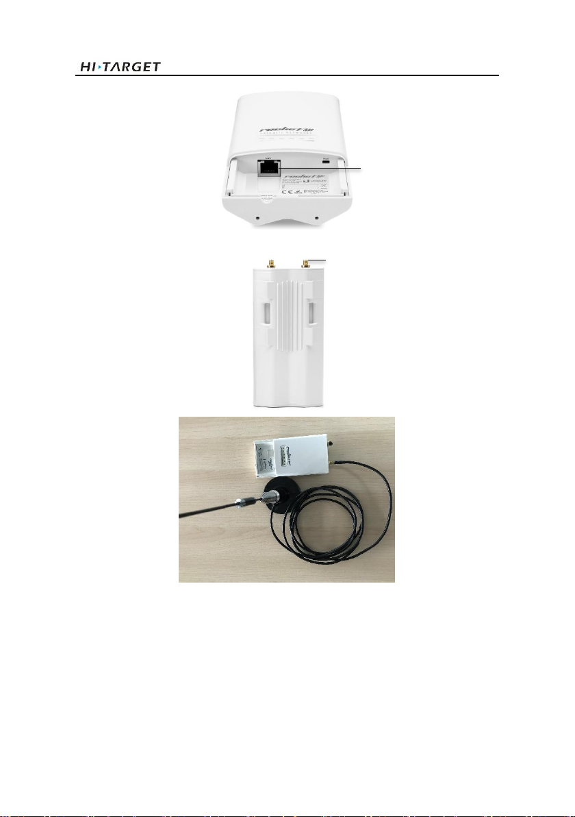
Figure 1-4 Wireless bridge connection
Then the wireless bridge will transmit the signal to the shore-based omni-direction antenna,
which equipped with magnetic base easy to be mounted on the meddle platform such as car roof.
Wireless bridge Ethernet port
Connect with omni-direction antenna
BS2 USV User Manual
6
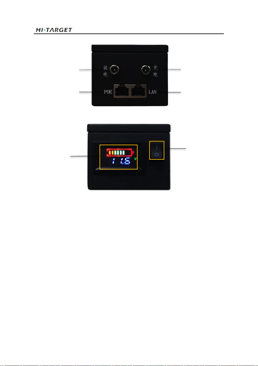
Figure 1-5 Base Battery and connection
Figure 1-6 Working state of battery
Power on the black battery (don’t forget it is a POE power supplier also), the screen indicates
power and related information. The green grids indicate the power left in the battery. Users need
to notice that the Power Switch button should be turned on when the battery charge or discharge.
Charging Port
Discharging Port
Battery
Indicator
Power Switch
POE Port
LAN Port
BS2 USV User Manual
7
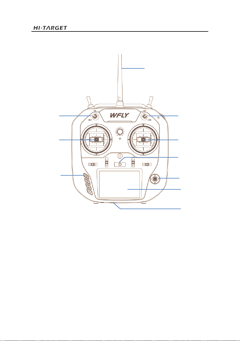
Describing essential parts of the controller:
Antenna
Left Stick
Right Stick
Power Button
Touch Screen
Function Button
SB Rod
SC Rod
Navigation Button
USB Port
BS2 USV User Manual
8
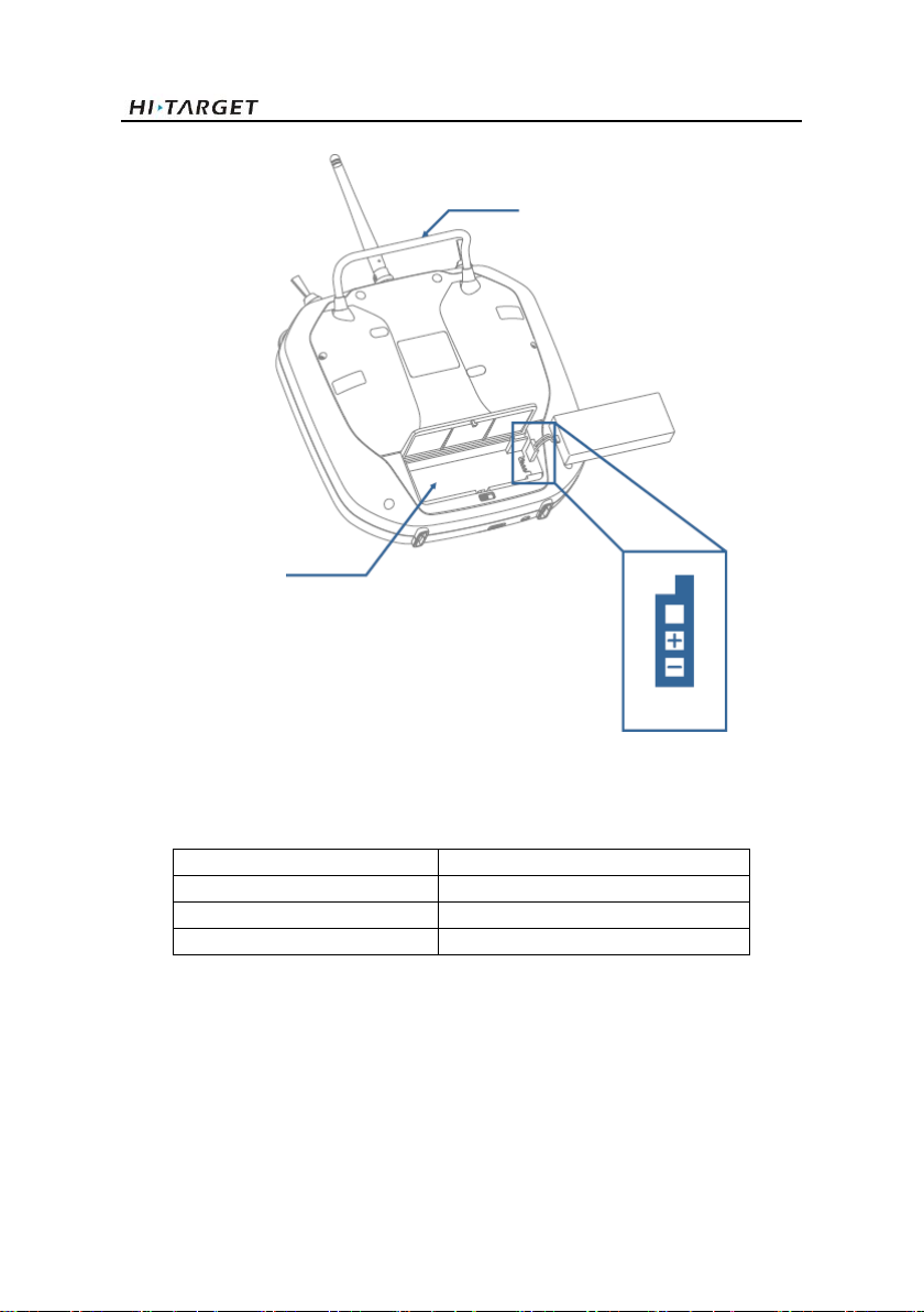
Figure 1-7 Description of functional parts
Table 1.1 Specification of controller
Working voltage
3.7V (lithium battery)
Working current
≤260 mA
Frequency
2.4GHz
Display
3.5-inch touch color screen, 480*320
Handle
Battery compartment
Battery
interface

BS2 USV User Manual
9
Figure 1-8 Description of SB and SC Rod
There are 3 operational modes controlled by the Left Stick on the controller (marked as SB).
From the top to the lowest they are Auto Mode, Manual Control Mode, Hold Mode.
B1-Auto Mode: The current mode is an automatic cruise.
B2-Manual Control Mode: The boat under the manual control mode.
B3-Hold Mode: The mission control system has no any output commands, propellers and other
related units will stop working.
And there are 3 operational modes controlled by the Right Stick on the controller (marked as
SC). From the top to the lowest they are Fixed-speed Cruising Mode, Hold Mode, RTL Mode.
C1-Fixed-speed Cruising Mode: The boat cruise at a fixed speed set by the laptop on the shore.
C2-Hold Mode: Same as above in SB Rod.
C3-RTL Mode (return to the home point): Return to home point.
Notes: When you encounter an emergency, you can swing the SB Rod and made the rod at Hold
mode to stop the working of propellers, this can avoid some collisions.
Description of functional button
B1
B2
B3
Auto Mode
Manual Control Mode
Hold Mode
C1
C2
C3
Fixed-speed Cruising Mode
Hold Mode
RTL Mode
4 direction optional button and press the center button can conduct the conformation

BS2 USV User Manual
10
Figure 1-9 Description of functional button
Manual control description
Figure 1-10 Description of Left&Right Stick function
- Left Stick
The left stick controls cruising direction and the speed: Forward/Back and Increase/Decrease.
You can see from the image above.
-Right Stick
The right stick controls the of change the direction it is pointing, to the left or right of its direction
of motion. You can see from the image above.
Forward & Increase
Back & Decrease
Yaw
Lift/Right
HOME: Function button, short press to return to standby interface.
EXIT: Exit button, short press to return to superior interface; long press 2s to
lock/unlock the screen.
+ : increase the parameter, switch the mode.
- : increase the parameter, switch the mode.

BS2 USV User Manual
11
Overall Operation Flow
2.1 Power on Controller
Press the power button to switch on the controller. It will give the voice feedback during
initialization. Push down the left control stick to manually confirm the system setup. Press the
button Back if an alarm sounded by the controller, due to no operation had been done to it for a
while.
2.2 Switch on USV
Switch on the USV and you will hear “di di di” sound. When a long “di---” comes, the
initialization is done (Please make sure the controller is powered on before turning on the USV).
Use the right control stick to activate the propellers by turning it left and right, checking the USV
health of the engine system. This checking step can be done on the ground before deploying it
into the water.
2.3 LAN IP Setting
Open the network configuration page of your laptop and set the local network IP (IPV4) to
192.168.1.88, the mask will set as 255.255.255.0 automatically. Keep others as default like the
following figure and confirm the settings.
Figure 2-3-1 LAN IP setting
BS2 USV User Manual
12
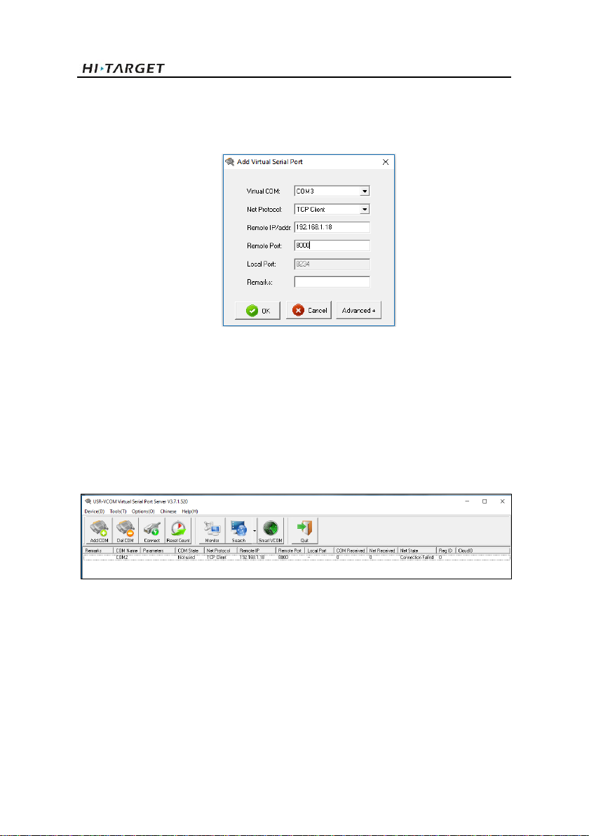
2.4 Run Virtual Serial Port Software
Run installer USR-VCOM.exe and then run the program immediately. Add a new virtual serial
ports as below.
Figure2-4-1 Virtual serial port configuration
Two Virtual Serial Port configuration as follows:
Port function: GNSS connection
Virtual COM: COM3(can be customized)
Net Protocol: TCP Client
Remote IP/Addr: 192.168.1.18
Remote Port: 8000
Remarks: GNSS connection
Figure2-4-2 Connecting status
When the ports set up, The Connected will be displayed and data income increase if everything
goes well. Minimize it and keep the program running in the background.
2.5 Setup GNSS Receiver by Hi-MAX
Firstly, insert the Hi-MAX dongle (the orange color one) into the laptop, register if necessary.

BS2 USV User Manual
13
Figure 2-5-1 Main interface of Hi-Max
2.5.1 New Project
Figure 2-5-2 New project creating
The project name is at the top of the project list once it had been created.
BS2 USV User Manual
14
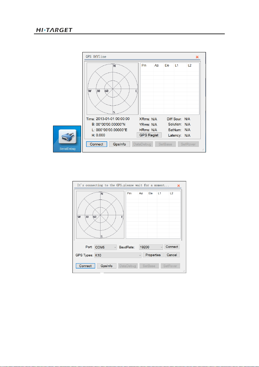
2.5.2 Serial Port Debug
Figure 2-5-3 Serial port debug
Click Connect GPS button
Figure 2-5-4 GPS connecting
Set the correct parameters and choose the right receiver type, click Connect.
BS2 USV User Manual
15
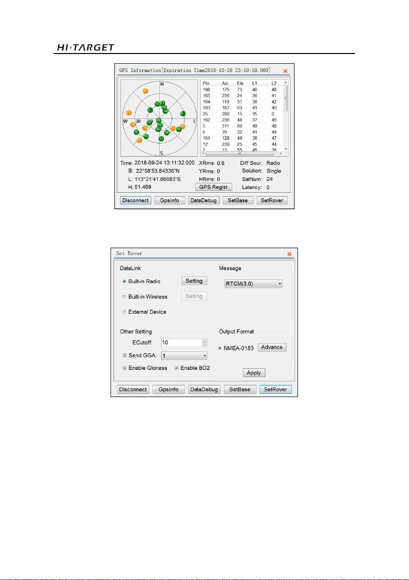
Figure 2-5-5 GPS information
On the top of the window shows the expiry date of the GNSS receiver. Restart the receiver if a
license is applied. Click SetRover Button.
Figure 2-5-6 Rover setting
Select the DataLink format. If there is the base station, choose the Built-in Radio mode. Click
Setting and enter the channel number in the pop-up Radio Setting window. Click OK for
conforming.

BS2 USV User Manual
16
Figure 2-5-6 Radio setting
If use CORS, select the Built-in Wireless mode.
Figure 2-5-6 Built-in wireless
Click Setting.
Table of contents
Other Hi-Target Boating Equipment manuals


