Seafloor EchoBoat ASV User manual

Seaoor Systems, Inc. | Info@seaoorsystems.com | +1 (530) 677 - 1019
EchoBoat
SeaoorTM TM
Model # ASV/RCV
Unmanned Survey Vessel

Congratulations on your recent purchase of the Seaoor EchoBoat Unmanned Surface Vessel or
“USV”. It was designed specically to allow the hydrographic surveyor to reliably and effectively
tackle hydrographic surveys in shallow waters or difcult to reach areas when conventional survey
boats are not an option. The EchoBoat features all non-corrosive materials and dual thruster motors
for ease of control and operation. It has an integral transducer well and allows for multi-sensor
payload capability.The EchoBoat’s multi-payload remotely controlled surveying function combined
with its portability makes owning and operating this remote control survey vessel affordable to all in
the Hydrographic Community. The combination of improved thruster pod and hull design allows for
large payload capacities, making the EchoBoat capable of handling all modern and advanced
microelectronics in the dynamic conditions of inland waterways.
If you are adding the optional AutoNav™ Auto-Pilot Module:
The survey vehicle can be monitored while underway, in both Auto and Manual modes. The mission
planner application runs on board the EchoBoat, controlled with remote desktop connection and
displays the vehicle’s positioning and progress against a background map of the survey area. Battery
voltage remaining may be monitored via the remote.
Switching from autonomous operation to manual control is as easy as ipping a switch on the long
range remote control system. Featuring an optional 2km range upgrade, combined with a survey
endurance of over eight hours, the Echo Boat is a viable survey vessel
Parts List
Number Description QTY
9Skeg 2
8WiFi Antenna Cable 1
7 WiFi Antenna 1
6Hardware Pack 1
5Battery Charger 1
4Remote Control 1
3Forward Mast Support 1
2Aft Mast Support 1
1Mast 1
10 Stern Pole Mount Bracket 2
EchoBoat
SeaoorTM TM
Model # ASV/RCV
Unmanned Survey Vessel
1
4
2
3
7
6
10
5
9
8
v2 - 10/02/19 Page 1 of 15
Seaoor Systems, Inc. | info@seaoorsystems.com | +1 (530) 677 - 1019

EchoBoat Safety and Cautions
Always practice caution when working with electricity in water and with the spinning blades of the
propeller. The propellers can rotate up to 3,800 RPM and draw 350W producing a max thrust of
11.2 lbs. each. Keep body parts away from the thruster inlet and outlet to avoid injury.
Prior to use, please read the included battery instructions. Failure to observe the included
precautions can result in re, explosion and cause personal injury/property damage.
Do not operate the thrusters for an extended period outside of the water. The bearings are
lubricated by the water, therefore vibration and noise will be greater when dry. A slight clicking
noise is normal, especially when operated dry. This is caused by slight movement of the shaft in
the plastic bearings.
The thrusters can handle saltwater and sandy environments however, to avoid damage refrain
from sucking debris into the thruster.
NEVER leave batteries connected while the EchoBoat is unattended. Always disconnect all
batteries immediately after use.
• Even with the power switch in the off position the batteries may discharge below the
reccomended safe levels of discharge.
When powering up the EchoBoat, always turn on the remote control unit before powering the
boat. If, when powered up, the receiver on the boat does not detect a controller signal, the
remote control unit may unexpectedly enter the fail-safe mode. This could be extremely
dangerous.
Conversely, when shutting down, always power down the boat using the rear thruster switches
switch on the rear of the boat before shutting down the remote control. Again, if the remote
control unit is shut off before the boat, unexpected and possibly very dangerous maneuvers may
occur.
Improperly installed instruments can cause the boat to ll with water. Never try to operate the
EchoBoat without properly installed instruments.
Typical Survey Speed ....................................... 3 kts (1.5 m/s)
Top Speed ....................................................... 5 kts (2.5 m/s)
Hull Width ........................................................ 0.8 m
Hull Length ...................................................... 1.8 m
Battery Endurance – Survey Speed ................ 8 hours
Payload............................................................. 34 kg / 75 lbs
Power .............................................................. 4x 14.8V (4S)16 Ah LiPo battery (Thrusters & AutoNav)
.............................................................. 2x 22.2V (6S) 22Ah LiPo battery
(Sonar, PC & Other Auxiliary Equiptment)
Motor ................................................................ 2x brushless thruster
Hull Material ..................................................... UV resistant HDPE
Steering .......................................................... Differential
Weight ............................................................ 31 kg / 69 lbs empty, no electronics
Hardware ......................................................... Stainless steel
Remote Control Unit ........................................ 2.4 GHz (900 MHz optional) Long Range
Remote Antenna .............................................. Omnidirectional
Remote Range ............................................... 2 km with 900 MHz line of sight (optional)
GPS ................................................................. Customer specied
Communications .............................................. 900 MHz spread spectrum radio modem, or USB
Depth Sounder Transducer ............................ Through hull mount
EchoBoat Specications
v2 - 10/02/19 Page 2 of 15
Seaoor Systems, Inc. | info@seaoorsystems.com | +1 (530) 677 - 1019

EchoBoat-G2 Warranty
Seaoor Systems, Inc. makes every effort to assure its products meet the highest quality,
reliability and durability standards and warrants to the original purchaser or purchasing agency
that each EchoBoat be free from defects in materials or workmanship for a period of one year
from date of shipment.
Warranty does not apply to defects of misuse, negligence or accidents. Warranty also does not
cover repairs or alterations outside of our facilities, use of the EchoBoat for purposes othe than
water measurements, or use with instruments weighing more than 75 pounds.
Seaoor is not responsible for loss of boat, instruments, damage to property, or injury/death
associated with the use of any of its products or 3rd party products that may be included or used
with Seaoor products. Seaoor does not warranty third-party products sold by Seaoor. These
may include GPS, depth sounders and other ancillary equipment.
All warranty services are FOB Seaoor’s facility in Shingle Springs, California, U.S.A.
Optional Equipment
Sonar:
Multibeam EchoSounder
Singlebeam EchoSounder
Dual Frequency EchoSounder
Side Scan Sonar
ADCP
GPS:
RTK/GNSS
Differential GPS
Auxiliary:
Sound Velocimeter
Sound Velocity Proler (SVP) CTD Instru-
ment
Wi-Fi remote desktop
Auto Pilot Module:
AutoNav Control System
Built-in Telemetry System
PC
Mission Planner Application
900 MHz Long Range Remote Control
v2 - 10/02/19 Page 3 of 15
Seaoor Systems, Inc. | info@seaoorsystems.com | +1 (530) 677 - 1019

Before unpacking your EchoBoat prepare a
boat stand to allow the EchoBoat to sit level
and give you access to the underside of the
hull. A 2x4 frame with pipe insulation foam that
will protect the hull from scratches works well.
Seaoor Systems also offers the EchoBoat
EchoCart, a rugged metal frame with padded
supports and wheels for easy transporting and
launching.
Remove bubble wrapped Mast, Mast
Supports, Battery Charge Box and other
items packed around the EchoBoat and
set aside.
Prepare a stand for the EchoBoat at the Bow
side of the packing crate. With two people,
one on either side of the EchoBoat, lift the
EchoBoat out of the crate bow rst and place
on the stand. Lift from installed handles.
Open the hull of the EchoBoat by loosening the black knobs around the perimeter of the
hull lid. Then remove the remote control, hardware pack and any other optional items that
are packed in the hull of the EchoBoat. Next reinstall the hull lid, it is not necessary to fully
tighten the hull lid at this time.
Step 4
Assembling your EchoBoat
Step 1
Step 2 Step 3
v2 - 10/02/19 Page 4 of 15
Seaoor Systems, Inc. | info@seaoorsystems.com | +1 (530) 677 - 1019

With the provided ¼” Allen
key driver, remove the four
handles from the sides of the
EchoBoat.
Carefully unwrap the Mast
and Mast Supports from the
bubble wrap.
Step 5
Identify the forward Mast
Support by the angled
feet that t the curve of
the EchoBoat.
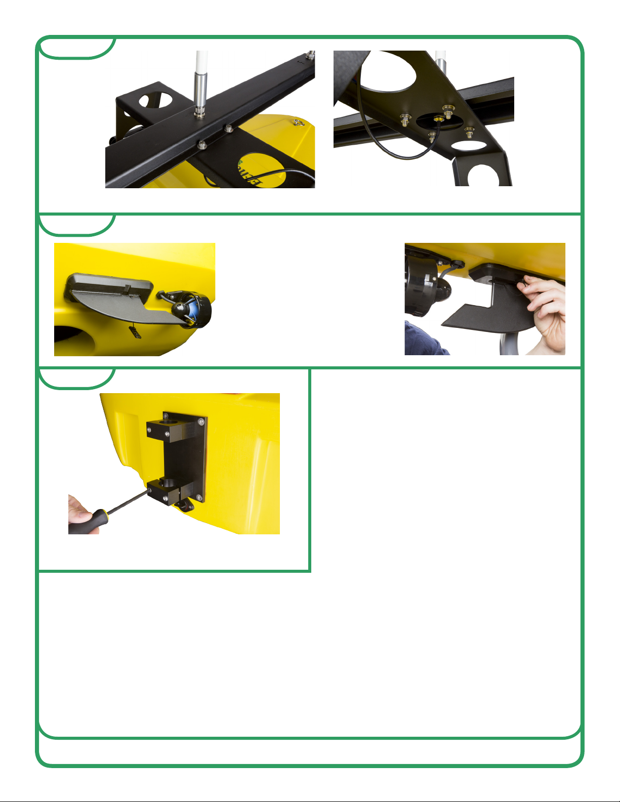
Loosely install the Mast Supports with the
previously removed handles and hardware.
The rubber washers should be installed
between the hull and the Mast Support feet.
With a ½” end wrench and the provided ¼”
Allen key driver, install the mast with the
included hardware. The Mast is marked with
an “F” for forward.
All hardware for the Mast and Mast Supports should be tightened at this time.
Step 6 Step 7
Step 8 Step 9
Step 10
Step 11
Install WiFi antenna cable to the base of the antenna
mount on the bottom of the Mast and the other end to the
antenna bulkhead connector under the Mast Support leg
on the starboard side of the EchoBoat.
v2 - 10/02/19 Page 5 of 15
Seaoor Systems, Inc. | info@seaoorsystems.com | +1 (530) 677 - 1019
To install the Skegs, slide the
skegs into the skeg mounts on
the underside of the hull from
the bow to the stern. Once skegs
are fully inserted into the skeg
mounts, slide locking pin into the
slot on the mount to lock ns in
place.
Install rear stern pole mount bracket with the
provided 3/16” allen key.
The EchoBoat is now fully assembled.
Before moving forward, please review
the battery charging instruction manual
and charge the 14.8V(4S) and 22.2V(6S)
batteries. Please also review the remote
control instruction manual for controls and
charging instructions.
Step 13
Step 14
Step 12
Install WiFi antenna by simply screwing it to the pre-installed antenna mount on the Mast.
v2 - 10/02/19 Page 6 of 15
Seaoor Systems, Inc. | info@seaoorsystems.com | +1 (530) 677 - 1019

Installing the Batteries
Prior to use ensure the four 14.8V(4S) batteries and two 22.2V(6S) batteries are fully
charged. See battery charging manual for instructions.
Remove hull lid by loosening all black
knobs around the perimeter of the hull
lid and set aside.
The four 14.8V(4S) batteries that power the
thruster motors and AutoNav are installed at the
stern of the EchoBoat. To install, remove the four
thumbscrews on the battery hold down straps.
The four Venom 14.8V(4S) batteries should be
oriented with two battery cords towards the port
side and two cords toward the starboard side.
If you are using the Turnigy batteries, point all
cords toward the center of EchoBoat.
Reinstall the battery hold down straps with
the four thumb screws.
Plug the four batteries into the
EchoBoat with the XT90 plugs.
Step 2 Step 3
Step 4 Step 5
Step 6
Step 1
v2 - 10/02/19 Page 7 of 15
Seaoor Systems, Inc. | info@seaoorsystems.com | +1 (530) 677 - 1019
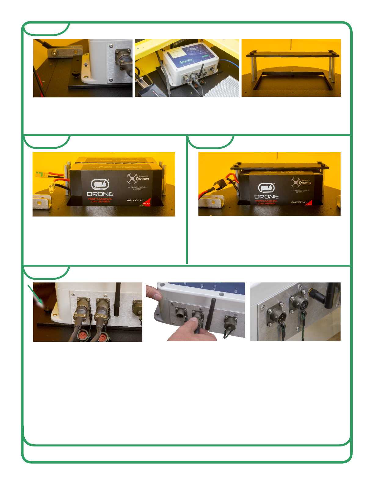
The two 22.2V (6S) batteries that supply power to installed electronic equipment (Sonar,
auxiliary equipment and PC) are installed in the bow of the boat forward of the AutoNav.
To install batteries, remove AutoNav unit, then remove battery hold down straps and place
batteries in battery tray.
The 22.2V (6S) batteries should be
oriented with the cords towards the port
side of the EchoBoat. Reinstall the
battery hold down straps with the four
thumb screws.
Plug the two 22.2V (6S) batteries into the
EchoBoat with the XT90 plugs.
Step 7
Step 8 Step 9
Step 10
If the two 22.2V(6S) batteries are unable to be installed by simply swinging the AutoNav to
the side, it may be necessary to remove the AutoNav completely.
A) Remove the four thumbscrews on the four corners on the AutoNav
B) Remove the PORT and STBD power cords to the AutoNav. Remove the USB cable on
the starboard side. The AutoNav can now be removed to allow the batteries to be installed.
C) After the batteries have been installed the AutoNav can be reinstalled. Make sure to
reinstall the USB cable tightening the thumbscrews. Take note that the PORT and STBD
power cords are male and female keyed. The female cord goes into the PORT side and the
male cord goes into the STBD side. They can be installed improperly.
v2 - 10/02/19 Page 8 of 15
Seaoor Systems, Inc. | info@seaoorsystems.com | +1 (530) 677 - 1019
Powering Up EchoBoat
Ensure the remote-control
battery is fully charged.
See the remote control
manual for instructions.
Review the remote
control manual if you are
not familiar with it.
Power on remote-control.
Pull left joystick down
and return to center.
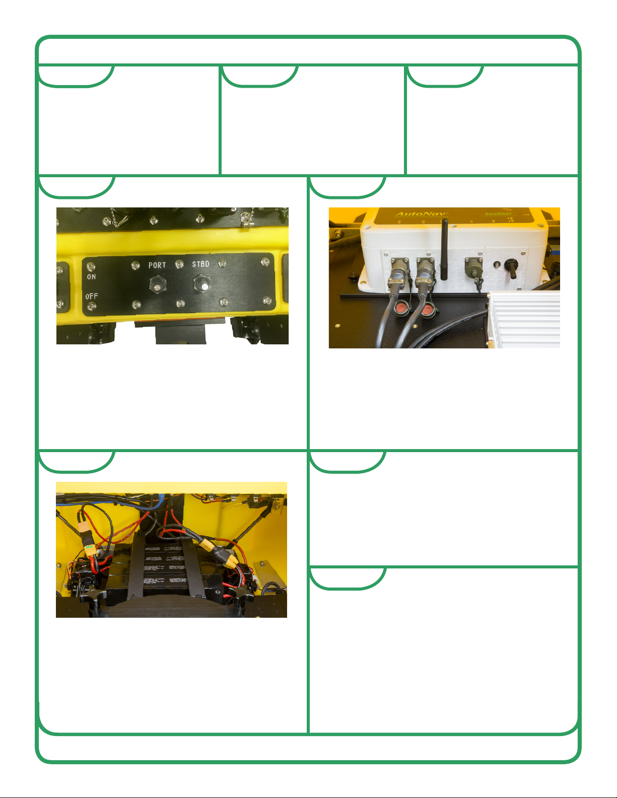
Turn on the AutoNav using the switch on
the starboard side of the AutoNav.
Power on thruster motors with the two
switches, labeled PORT and STDB, on the
stern of the EchoBoat. This will turn
AutoNav on if the switch is in the on
position.
Wait approximately 15 seconds for speed
controllers to pair. They will go through a
series of tones and LED ashes.
Using Arming switch on top right the
remote arm AutoNav from the remote
control. AutoNav will chime when armed.
Reinstall hull lid and tighten all black knobs
in a star pattern, not clockwise or
counter-clockwise, to ensure a uniform
seal. For Example - top left, bottom right,
top right, bottom left, etc..
Step 1 Step 2 Step 3
Step 4 Step 5
Step 8
Step 7Step 6
v2 - 10/02/19 Page 9 of 15
Seaoor Systems, Inc. | info@seaoorsystems.com | +1 (530) 677 - 1019

Testing Thruster
Before launching the EchoBoat check the thruster motors for proper operation.
These thrusters are lubricated by water and should be wet for the following test.
Do not run the thrusters for more than a few seconds out of the water.
B Refer to propulsion system calibration procedures if you notice the thrusters
are not spinning evenly, or if the propulsion system does not operate as outlined in
the thruster test below.
Note: the thruster motors are designed to be counter rotating. With forward thrust
both propellers should rotate inboard, that is, port propeller rotates clockwise and
starboard propeller rotates count-clockwise (as viewed from standing behind boat).
With reverse thrust the propellers should rotate outboard.
C Forward Thrust Test: While holding a piece of paper approximately 6 inches aft
of each thruster motor, slowly push throttle joystick on remote control unit straight
forward. The paper should be pushed away from the thruster motors, that is,
thruster motor will blow air aft of the boat. This indicates forward thrust of the boat.
D Reverse Thrust Test: While holding a piece of paper approximately 6 inches
aft of each thruster motor, slowly pull throttle joystick on remote control unit straight
backwards. The paper should be pulled toward the thruster motors, that is, thrust-
er motor will blow air toward bow of boat. This indicates reverse thrust of the boat.
E Turning Thrust Test: The propulsion systems uses differential thrust to turn the
boat, that is, as one motor provides forward thrust the other motor provides reverse
thrust.
Use the paper technique to test forward and reverse thrust of each motor while
turning port and starboard.
Turn to port:
Slowly push throttle joystick on remote control unit forward and to the left. The
port motor will provide reverse thrust and the starboard motor will provide forward
thrust.
Turn to starboard:
Slowly push throttle joystick on remote control unit forward and to the right. The
starboard motor will provide reverse thrust and the port motor will provide forward
thrust.
1
2
3
4
v2 - 10/02/19 Page 10 of 15
Seaoor Systems, Inc. | info@seaoorsystems.com | +1 (530) 677 - 1019

Power Off
B Turn off Sonar and auxiliary equipment using installed software programs, save les,
then close software programs. Then, turn off Sonar and Aux power switches on stern of
boat.
Never turn off PC using PC power switch on stern of boat.
Alway turn off PC using Windows Start menu power button shut down, only then turn off
PC power switch on stern of boat.
C Turn off the thrusters with the PORT and STBD switches at the rear of the EchoBoat,
this will turn off AutoNav.
D Lastly turn off remote-control.
E Disconnect the 14.8V (4S) and 22.2V (6S) batteries at the XT90 connectors.
F Allow the batteries to fully cool and perform a storage charge if the EchoBoat will not
be used the following day otherwise fully charge the batteries.
• NOTE – Leaving the LiPo batteries at too high or too low of a state of charge for
extended periods of time will cause irreversible damage to the batteries.
5
1
2
3
4
Launching and Retrieving the EchoBoat
B Before launching the EchoBoat, ensure the drain plug is tight and hull lid is secure.
C Power up the EchoBoat and test thrusters before launching.
D Check that the remote-control joysticks are in the center position prior to launching the
EchoBoat.
E The EchoBoat should be launched stern rst. This will protect the thrusters from
accidental grounding and possible damage. Please be mindful of your sonar and payload
F Thoroughly familiarize yourself with the way the EchoBoat responds to the controls
before deploying in moving water. When the EchoBoat is traveling away from you it will
respond to control signals as expected. When the EchoBoat is inbound (traveling
toward you) the controls will be the same but can cause confusion. Please practice in
calm water, close to shore until you are familiar with how the controls respond when the
EchoBoat is traveling towards you and away from you.
1
2
3
4
5
v2 - 10/02/19 Page 11 of 15
Seaoor Systems, Inc. | info@seaoorsystems.com | +1 (530) 677 - 1019
The EchoBoat is designed for easy maintenance. The following tips will help to prolong
the life of the EchoBoat and its components.
B To prolong the life of the HDPE hull and nish, wash with mild soap and water after
each use. Always ush thruster motors after use. Alternate forward and reverse thrust
several times while motors are submerged in clean, fresh water, or while spraying water
on motors.
C IMPORTANT Rinse EchoBoat after use in saltwater and clean out biofouling and
debris occasionally.
D Do not run the thrusters at high speeds or for an extended period out of the water to
minimize noise and wear.
E Check the access hatch gasket for cuts, cracks or deformation. This gasket seals the
instrumentation area from water intrusion and should be checked frequently.
F Lube gaskets where needed.
F Carefully inspect all batteries prior to and following each use per the instructions
provided for the batteries. Should any physical damage, swelling or “ballooning” be
evident please refer to the disposal steps covered in the battery instructions.
H Check to make sure all EchoBoat hardware is tight.
MAINTENANCE
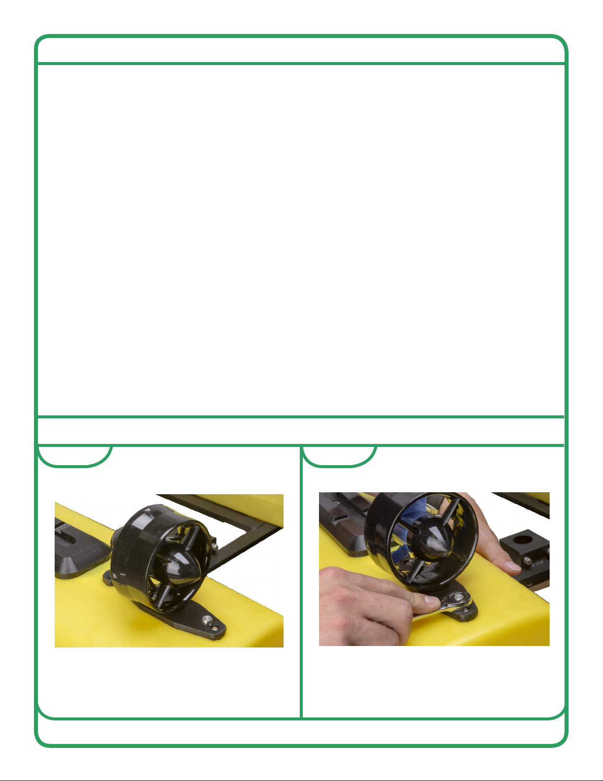
CLEANING AND REPLACING THRUSTERS
Cleaning thrusters periodically is important
to prolonging thruster life.
With 3/8th or 10mm socket or end wrench
remove the nuts on thruster plate that are on
either side of the thruster.
Step 1 Step 2
v2 - 10/02/19 Page 12 of 15
Seaoor Systems, Inc. | info@seaoorsystems.com | +1 (530) 677 - 1019
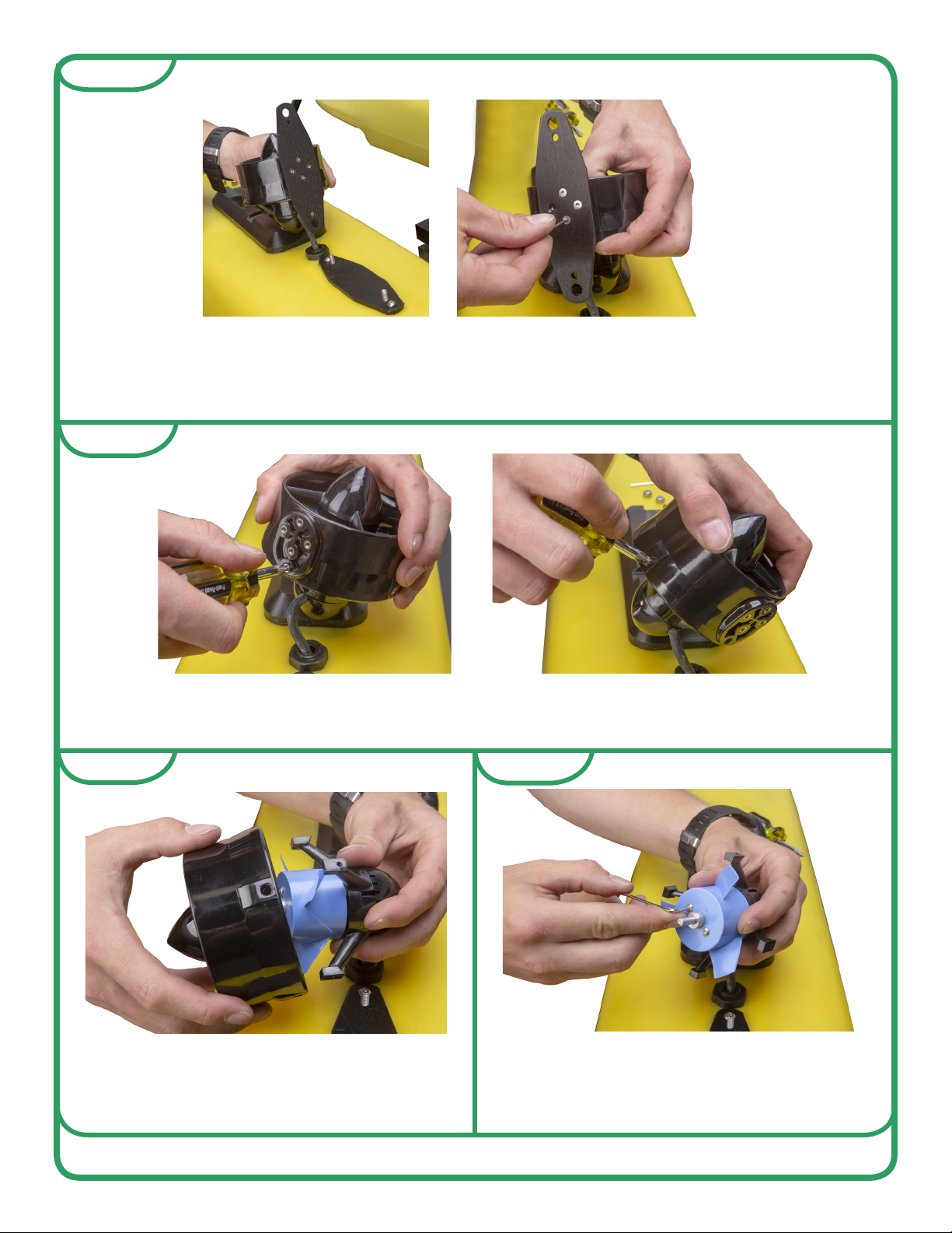
Step 4
Once nuts are removed, the thruster plate and thruster will lift off the boat and expose the
m3x6 allen screws that hold the thruster plate to the thruster. Remove the thruster plate
from the thruster by removing those four screws with 2 mm allen key. If you are replacing
the thruster skip to step 10.
Remove the four #2 Phillips screws along the outer edge of the thruster.
Pull the base and propeller out of the nozzle
and tail cone.
Remove the 2mm allen screw that hold the
propeller to the motor assembly.
Step 6
Step 5
Step 3
v2 - 10/02/19 Page 13 of 15
Seaoor Systems, Inc. | info@seaoorsystems.com | +1 (530) 677 - 1019

Step 9
Remove the propeller from motor assembly by putting press on motor shaft while pushing
the propeller off of the the motor assembly. Be careful not to put too much pressure on the
propeller ns. No further disassembly is required.
Make sure to clean inside of the nozzle and
tail cone.
Step 8
Step 7
Most importantly clean the area between
the motor assembly and the thruster base
as well as the gap, as long grass, shing
line, anything thin and long will end up in
there. A paperclip or small Allen key works
for cleaning it out..
v2 - 10/02/19 Page 14 of 15
Seaoor Systems, Inc. | info@seaoorsystems.com | +1 (530) 677 - 1019

Step 10
To completely remove and replace the thruster;
from inside the hull of the EchoBoat, remove
the compression-tting nut with 3/4 end wrench.
Then remove the white, blue, and green wires
from the EchoBoat wiring harness. From the
outside of the EchoBoat, use a small allen key or
punch to press the grey gasket out of the
compression tting. The thruster wire will now
pull through the EchoBoat hull. Install new
thruster by putting new wire through hull then
slide grey gasket followed by the nut, up the wire
from inside the hull. Plug wires back into wiring
harness and tighten compression tting.
Step 11
Reverse these steps to reassemble thruster.
v2 - 10/02/19 Page 15 of 15
Seaoor Systems, Inc. | info@seaoorsystems.com | +1 (530) 677 - 1019
This manual suits for next models
1
Table of contents
Other Seafloor Boating Equipment manuals

Popular Boating Equipment manuals by other brands

Floe
Floe V-2000 Assembly instructions

Ultraflex
Ultraflex UC 128-TS Installation and maintenance manual

Power-Pole
Power-Pole Blade installation manual

Anchorlift
Anchorlift Barracuda 600 User manual and installation guide

JOBE
JOBE Addict Adjustable Pro Ski Pylon quick guide

Seastar Solutions
Seastar Solutions Seastar PROTAP Controller Installation instructions and owner's manual


