Simrad AP14 User manual

Manual
Simrad AP14
Autopilot

Page 3Page 2
The technical data, information and illustrations contained in this publication were to the best of our knowledge correct at the time of going to print. We reserve the right
to change specifications, equipment, installation and maintenance instructions without notice as part of our policy of continuous development and improvement.
No part of this publication may be reproduced, stored in a retrieval system or transmitted in any form, electronic or otherwise without prior permission from Simrad
Navico Ltd.
No liability can be accepted for any inaccuracies or omissions in the publication, although every care has been taken to make it as complete and accurate as possible.
© 1999 Simrad Navico Ltd
For service and advice please contact the main Simrad dealer in your country of residence.
E03716 Issue 1.1
30/11/1999 MDL
1. General
1.1 Introduction
1.2 AP14H & AP14R Configurations
2. Operation
2.1 General
2.2 Autopilot Mode
2.3 Adjusting Course
2.4 Nav Mode
2.5 Set Key
2.6 Dodge
2.7 Backlighting
2.8 Alarms
2.8.1 Off Course Alarm
2.9 Default Boat Speed
2.10 Adjusting Dodge Angle
3. Parameter Adjustment
3.1 Rudder Movement (Gain)
3.2 Seastate
3.3 Autotrim
4. Installation - AP14H Hydraulic Drive
4.1 Pump Installation SRP12
4.2 Bleeding The Steering System
4.2.1 Two or Three Line Systems
4.2.2 Pressurised Systems
4.3 Linear Feedback Unit SLF12
4.4 Fitting Control Unit SHC14
4.5 Fitting Compass Unit SHS12
4.6 Fitting Course Computer SCP12
4.7 Electrical Installation
4.8 Interfacing via NMEA
CONTENTS
5. Installation - AP14R Rotary Drive
5.1 Drive Installation
5.2 Removing Existing Steering Helm
5.3 Fitting Drive Unit SRD12
5.4 Changing the Steering Cable
5.5 Fitting Control Unit SHC14
5.6 Fitting Compass Unit SHS12
5.7 Electrical Installation
5.8 Interfacing via NMEA
6. Commissioning
6.1 Commissioning Checks
6.1.1 Installation Check
6.2 Compass Orientation
6.3 Compass Adjustment
6.4 Setting Rudder Limits
6.5 Seatrial / Compass Calibration
7. Appendix
7.1 Advice On Operation
7.2 Warning
7.3 NMEA Sentences Received
7.4 Fault Finding
7.5 Optional Accessories
7.6 Specification & Dimensions
7.7 Service & Warranty

Page 5
Fig 2.1 - Standby Mode (AP12H / AP14H)
Fig 2.2 - Engaging autopilot Mode
2 Operation
2.1 General
The keypad of the AP14 is easy to operate. Using the five
main keys it is simple to change modes, set the course to
steer and adjust navigational functions.
When powered up theAP14 enters Standby Mode indicat-
ed by the STBY legend in the display (Fig 2.1)
While in Standby Mode, the helmsman is in control. The
boat can be hand steered using the helm as normal, or
“power steered” using the and (Port and Starboard)
keys on the controller.
• All functions are confirmed audibly by a “beep” and
visually on the display. The display also shows the cur-
rent magnetic bearing of the vessel.
• If fitted to an AP14H version, the display will also show
the rudder angle (Fig 2.1).
2.2 Autopilot Mode
To engage Autopilot Mode, press the Stby/Auto key and
the pilot will lock onto the current course (Fig 2.2). The
AUTO legend will show on the display while the pilot is
in Autopilot Mode.
• To lock the pilot onto the desired course, either steer the
correct course and then engage the pilot, or engage the
pilot and then adjust the heading until the correct course
is being steered (see section 2.3).
AP14R Rotary Pilot - it is recommended that if a sudden
course change is necessary while in Auto Mode (e.g. to
avoid an obstacle) the clutch is disengaged and the
autopilot is returned to Standby Mode by pressing
Stby/Auto. In an emergency the clutch can be overridden by
firmly turning the steering helm, although the autopilot will
try to bring the boat back to the set course.
AP14H Hydraulic Pilot - The autopilot must be disen-
gaged by pressing Stby/Auto if a sudden course change
is necessary otherwise the autopilot will counteract any
movement made manually to the helm.
Page 4
1 General
1.1 Introduction
Combining sophisticated electronics with advanced software and powerful drives, the Simrad AP14
autopilot provides accurate and dependable steering in varying sea conditions with minimal current
consumption.
The AP14, a state of the art autopilot system with many advanced features, is simple to operate and
occupies little space on the dash. The keypad accesses all functions and pilot status is indicated clear-
ly in the backlit LCD display.
To ensure the best results from your autopilot it is essential that the unit is installed correctly -
please read this manual thoroughly before attempting installation and use.
Thank you for choosing Simrad
We hope you will also be interested in our full range of marine electronic equipment, which are all man-
ufactured to the same high standards as the AP14. Please contact your nearest Simrad Agent for a cat-
alogue showing our full range of high tech marine electronic equipment.
Simrad operate a policy of continual development and reserve the right to alter and improve the
specification of their products without notice.
1.2 AP14 System Configurations
The AP14 autopilot system is designed for power vessels and is available in two configurations.
• The AP14H - designed for hydraulically steered boats with a ram displacement of 15 in3(250cc).
• The AP14R - designed for powerboats with a push-pull steering cable system which are 30 ft (9M) or
smaller in length.
Although the operation and functions of these two versions are identical, there are some differences
in the configuration and installation of the AP14H and AP14R. To make installation easier, there are
two separate installation sections in this manual. Section 4 relates to the installation of the AP14H
Hydraulic version, section 5 is for the AP14R Rotary version. Some of the setup and calibration rou-
tines apply only to the AP14H, but this is clearly indicated at the beginning of the relevant section.
SHS12
Compass
SCP12
Course Computer
GPS
(NMEA)
SRP12
Hydraulic Pump
SLF12
Linear Feedback Unit
GPS
(NMEA)
SHS12
Compass SJB12
Junction Box
SRD12
Rotary Drive Unit
AP14H Hydraulic Drive Option AP14R Rotary Drive Version
Optional
Fixed
Control
SFC12
Optional
Fixed
Control
SFC12
Control
SHC14
Control
SHC14

Page 7
• If Cross Track Error data is being received, but no
Bearing To Waypoint data, then the display will show
“– – –” instead of the Bearing To Waypoint.
2.5 Set Key
The Set key performs several functions, including adjust-
ing the parameters of the AP14 such as seastate, dodge
angle etc. Refer to the relevant sections for more infor-
mation on these.
In addition, depending on the NMEAdata being received
by the AP14, the following data can be displayed by
pressing the Set key the specified number of times -
Press SET Data Shown
1Cross Track Error [XTE] (Fig 2.5)
2Bearing To Waypoint [BTW] (Fig 2.6)
3Distance To Waypoint [DTW] (Fig 2.7)
• The individual data will only be shown if it is being
received from the navigational receiver, so for example, if
BTW is not being received, the second press will show
DTW. Subsequent presses of the Set key will access func-
tions in the following order -
SEASTATE SETTING (Section 3.2)
OFF COURSE ALARM ANGLE (Section 2.8)
DODGE ANGLE (Section 2.10)
DEFAULT BOAT SPEED (Section 2.9)
Page 6
2.3 Adjusting Course
While in Autopilot Mode, precise course adjustments can
be easily made -
• Press the or key once to make a 1º course adjust-
ment, confirmed by one beep and on the display by the
new heading shown
• Press and hold the key for a 10º course change, con-
firmed by a double beep and on the display by the new
heading shown (Fig 2.3).
2.4 Nav Mode
The AP14 has an inbuilt interface which allows it to be
connected to NMEA0183 compatible equipment such as
GPS, LORAN, Chart Plotters etc.
Once connected, the AP14 can steer using data from this
source in addition to the compass, allowing a highly accu-
rate course to waypoint
• To enter Nav Mode the pilot must be in Auto Mode and
receiving waypoint or route data from the navigational
receiver.
Press Nav to activate Nav Mode (Fig 2.4). The display will
show NAV and the pilot will steer to the first waypoint.
• If no NMEA information is being received, the AP14
will beep twice and will not enter Nav Mode.
• If Nav is pressed while in Standby mode, the pilot will
beep once if Nav Mode is available when in Auto Mode,
or twice if Nav Mode will not be available.
At the target waypoint, an intermittent alarm will sound.
As a safety feature (to avoid an unexpected course
change) the next waypoint will not be loaded until the
Nav key is pressed again. When the boat reaches the final
waypoint, the pilot will switch back to Auto Mode, hold-
ing the current course.
Note - If a course correction is made while in Nav Mode
using the and keys, the boat will gradually return to
the original track, so that the boat can avoid an obstacle
without exiting Nav Mode or having to reset the boat on
the correct course.
Pressing Nav when in Standby mode will bring up the
current Bearing To Waypoint (BTW) on the display.
Fig 2.3 - Course adjustment to Port
Fig 2.4 - Activating Nav Mode
Fig 2.6 - Bearing To Waypoint
Fig 2.7 - Distance To Waypoint
Fig 2.5 - Cross Track Error
Nm
Nm
Return

Page 9
2.6 Dodge
The Dodge function allows the autopilot to dodge to port
or starboard by a specified angle (normally 40º), and then
return to the original course. This function is useful for
avoiding obstacles in the path of the boat.
A Dodge can only be initiated in Auto mode. Press the
Dodge key - the display will show DODGE.
• If no further key is pressed within 5 seconds, the dis-
play will return to normal.
Press either or within 5 seconds to choose the direc-
tion to dodge (Fig 2.8). The display will show the new
heading selected and DODGE will flash in the display.
Selecting a dodge in the opposite direction while the
manoeuvre is in progress will cancel it, and the boat will
return to its original course.
• The default dodge angle is 40º, but this can be adjusted
- see section 2.10.
2.7 Backlighting
To switch the display backlighting on and off, press
Light.
To set the backlighting level (1-5), press and hold Light.
The SHC14 will step through each lighting level, which
will be shown on the display (Fig 2.9). Release the Light
button when the desired lighting level has been selected.
• While the backlighting is on, the Lamp symbol will
be shown. The backlighting level set is retained by the
SHC14 even if it is disconnected from the power.
2.8 Alarms
When an alarm is triggered by the autopilotALARM will
flash in the display. To acknowledge and cancel the
alarm, press Alarm.
• The alarm may continue to sound at the autopilot if the
alarm condition still exists.
2.8.1 Off-course Alarm
The Off-courseAlarm will sound if the boat goes off course
further than a pre-set limit for more than 10 seconds.
To toggle the alarm on and off, press and hold the Alarm
FIg 2.8 - Dodging to Starboard
Press
& hold
Fig 2.9 - Selecting backlighting level
Page 8
key (Fig 2.10). The alarm icon will be displayed while
the alarm is on.
• If the off course alarm sounds, press Alarm to
acknowledge and disable the alarm.
The off-course limit can be set from 10-60º. Press Set (see
section 2.5) until ALARM appears at the bottom of the dis-
play (Fig 2.11). The display will show the alarm limit set.
While ALARM is shown in the display, press to increase
the value and to decrease it.
• If no key is pressed within 5 seconds, the controller will
return to the main display and the value currently
entered will be set.
2.9 Default Boat Speed
The AP14 needs to know how fast the boat is going for
accurate performance when in Nav Mode. If this infor-
mation is not available through the NMEA input, an
average value can be manually entered.
Press Set (see section 2.5) until SPEED appears on the
display. The main boat speed will be shown in knots.
Press to increase the setting and to decrease it.
• If no key is pressed within 5 seconds, the controller will
return to the main display and the speed currently
entered will be set.
• This option will not appear if the true boat speed is
being received through the NMEA input.
2.10 Adjusting Dodge Angle
The SHC14 is set with a default dodge angle of 40º, but
this can be adjusted to any value between 10 and 40º.
Press Set (see section 2.5) until DODGE appears in the
display and the display shows the current dodge angle.
Press to increase angle and to decrease it.
• If no key is pressed within 5 seconds, the controller will
return to the main display and the dodge angle currently
entered will be set.
Fig 2.10 - Turning off-course alarm on
Fig 2.11 - Setting off-course alarm
Pressed
3 times
Pressed
and held

Fig 3.4 - Auto Seastate
3.2 Seastate
In a rough sea, more heading errors will be
detected by the pilot as the heavy seas yaw the
boat back and forth. The pilot would normally
be overworked trying to correct every error,
causing unnecessary strain on the unit and
excessive drain on the batteries.
The AP14 monitors the course errors as it goes
and it allows a “dead band” within which the
boat can go off course without corrections being
made (Fig 3.3). This is automatically set and
updated by the pilot to give the best compro-
mise between course holding and battery con-
sumption, but can be set manually if wished.
The Seastate can be adjusted in all modes, with-
out interrupting the operation of the pilot.
Press Set (see section 2.5) until the display
shows SEA on the bottom line, along with the
Seastate setting (1-10º or “–” for the fully auto-
matic Seastate setting).
To increase the Seastate, press . To decrease,
press . To select auto Seastate, press until
“–” appears in the display (Fig 3.4).
• If no key is pressed within 5 seconds, the con-
troller will return to the main display and the
Seastate currently entered will be set.
3.3 Autotrim
To compensate for changing conditions, a rud-
der bias (sometimes known as rudder trim) is
applied in order to steer a straight course. The
amount varies according to factors such as
wind strength, boat speed, and trim tab setting.
If this was not done then the boat would tend to
veer off course.
The AP14 monitors the average course error
and applies a bias to the rudder to compensate
until the optimum condition is reached (Fig
3.5). This bias is applied gradually to not upset
the normal performance of the pilot, so it may
take a minute or so to fully compensate after a
major course change.
Fig 3.3 - Seastate “deadband”
Average Course
Fig 3.5 - Autotrim principle
COURSE HELD
WIND
&
TIDE
Autotrim
applied
(Course Without Autotrim)
Page 10 Page 11
3 Parameter Adjustment
The AP14 uses highly advanced steering soft-
ware, which constantly assesses how the boat is
being affected by the sea conditions. By adjust-
ing its own performance, the pilot is able to
maintain the most accurate course for these con-
ditions, just as a human pilot would. So in a
rough sea, the pilot is not overworked and bat-
tery drain is kept to a minimum.
3.1 Rudder Movement (Gain)
The AP14 will make corrections if it detects that
the boat is off course. How much rudder it
applies to correct this is set by the Gain (some-
times referred to as the rudder ratio).
• The Gain setting can be compared to driving
a motor vehicle - at high speeds, very little
helm movement is necessary to steer the vehi-
cle (LOW Gain). When driving at slow
speeds, more helm movement is necessary
(HIGH Gain).
• Fig 3.1A shows when the Gain is too low: the
boat takes a long time to correct the heading.
• Fig 3.1B is ideal - errors are quickly corrected.
• Fig 3.1C the Gain is too high - the boat starts
to “S”, or oscillate around the correct heading.
• Excessive Gain (Fig 3.1D) makes the boat
oscillate increasingly off course.
The Gain can be adjusted in all modes, without
interrupting the operation of the pilot.
Press Gain once. The display will show GAIN
on the bottom line, along with the Gain setting
(1-9). The default setting is 5, which should give
good course keeping in most situations.
To increase, press (Fig 3.2). To decrease Gain,
press .
• If no key is pressed within 5 seconds, the con-
troller will return to the main display and the
Gain currently entered will be set.
Fig 3.1 - Effects of Gain setting
Fig 3.2 - Adjusting Gain setting

Page 13
Balanced
Unbalanced
Fig 4.1 - Hydraulic ram types
4 Installation - AP14H
Section 4 covers the installation of the AP14H
Hydraulic version. Please refer to section 5
for AP14R Rotary version installation instruc-
tions.
4.1 Pump Installation
The AP14H links a reversing pump into the exist-
ing hydraulic steering system on the boat using T-
fittings. The pump reproduces the effect caused
by turning the helm, so the pilot can steer the boat
without attaching any device directly to the helm.
Confirm that the volume of the cylinder of the
hydraulic ram is within the capacity of the
SRP12 pump. For the pilot to operate efficiently,
the cubic capacity of the boat’s ram must be less
than 250cc (15 in3). With hydraulic systems the
ram size is related to the steering load.
• If the volume of the ram cylinder is not known
then an approximate calculation can be made for
a balanced cylinder (these have the rod emerg-
ing from both ends of the cylinder - unbalanced
rams have the rod emerging from one end only
- Fig 4.1).
Volume = 3.142 x S(R2- r2)
S= Stroke length
R= Cylinder bore radius
r = Push rod radius
If S, R and rare in inches, the volume will be in
cubic inches (in3). If they are in centimetres, then
the volume will be in cubic centimetres (cc).
An ideal location for the pump is in a
gas/inflammable vapour free area, where it will
not be immersed in water.
The pump accepts hoses with 1⁄4in NPT fittings.
NPT to BSP adaptors are supplied with European
versions to convert BSP hoses to NPT type if nec-
essary (Fig 4.2).
• Try to keep hydraulic fluid loss during connec-
tion to the pump as low as possible - this will
help to reduce the time and effort required later
to bleed the system of trapped air.
• Absolute cleanliness is essential - even the
smallest particle of dirt could clog the check
valves in the pump.
BSP System
NPT System
Fig 4.2 - SRP12 pump hose connections
Page 12
Fig 4.3 - Hydraulic pump & mounting dimensions
Components supplied -
M5 x 25mm st stl hex set screw x 4
M5 st stl plain washer x 8
M5 st stl full nut x 4
1/4in(NPT) - 1/4in BSP adaptor x 3 (European version only)

Fig 4.4 - Connecting pump to common hydraulic
steering configurations
Page 15
Three Line System
Pressurised System
Second steering position
(if applicable)
Second steering position
(if applicable)
Two Line System
Return port (use lower
port if two are fitted)
Page 14
• The helm unit must be fitted with check valves - most are fitted as standard. If not, it will be nec-
essary to install a separate check valve between the helm unit and the SRP12 pump.
Fig 4.4 shows the correct connection for the most common steering configurations on boats with
hydraulic steering. If the boat has a different steering system to the ones shown then consult the
steering manufacturer or a qualified marine engineer before attempting to install the SRP12.
• The hydraulic pump can be mounted in any orientation except upside down - that is, mount-
ed with the valve ports pointing straight down. The pump will not prime in this position.
Choose a location so that it can connect easily with the existing hydraulic system - check that there
is easy access to the pump hydraulic connections and valves before mounting. Bolt the unit secure-
ly to a sturdy part of the boat to avoid vibration that could damage the interconnecting hoses.
Remove the protective plugs from the valve ports and connect the pump to the steering system using
flexible hoses to reduce the vibration being transmitted from the pump to the hydraulic lines. Make
sure that the correct fittings are used and fit the NPT to BSP adaptors if necessary. If it is necessary to
seal a tapered fitting use a recommended hydraulic oil sealant - never use PTFE tape.
• If the boat has a pressurised steering system, always release the air through the valve on the reser-
voir before cutting the hydraulic lines.
• It is not important which way round the pump outlet connectionsA & B are connected to the steer-
ing lines, as the pilot automatically sets the correct polarity when the unit is configured.
4.2 Bleeding The Steering System
The hydraulic system should be bled according to the manufacturer’s instructions. Make sure the cor-
rect oil is used to fill the system. If there are no manufacturer’s instructions available then follow these
basic instructions -
• Bleeding the steering system is a job for at least two people - one at the helm and one at the ram.
• Allow at least 2 litres (4 pints) of hydraulic fluid when bleeding a single helm system, plus an extra
litre (2 pints) for each additional steering position.
• Use a cup to catch oil lost during bleeding - the oil can be reused if filtered through a fine mesh
first. Any contamination could clog or impair the functioning of the steering system.
• These instructions assume that turning the helm clockwise will extend the ram and turning it
counter-clockwise will retract it. The cylinder may be installed the other way around so that the
helm is turned counter-clockwise to extend the ram. Check the orientation before bleeding.
4.2.1 Two or Three Line Systems
1. Fill the helm or reservoir to the indicated fill line..
2. Loosen the hose fitting to port A on the SRP12 pump.
3. Turn the helm slowly from lock to lock until a steady stream of oil comes from the hose fitting.
Retighten the hose fitting.
4. Repeat steps 2 & 3 with port B.
5. Repeat steps 2 & 3 with the return (R) port.
6. Prime the SRP12 pump by connecting it directly to 12v and driving the rudder to the endstop (Red
to 12v+, Black to Ground). Reverse the connections (Black to 12v+, Red to Ground) to run the pump
to the other endstop. Make sure that the oil level in the helm/reservoir is kept topped up while doing
this. NOTE - Running the pump dry for more than a few seconds can damage it. The hoses run-
ning to the pump must be primed by following steps 2 to 5.

Page 17
4.2.2 Pressurised Systems
Bleeding a pressurised system is a more com-
plicated procedure than a standard two or three
line system. Simrad recommends that you
enquire with the steering system manufacturer
for specific bleeding instructions. However, the
following instructions apply to most Hynautic
or similar pressurised systems.
1. Loosen the relief valve screws. Unscrew by
hand counter-clockwise as far as they will go.
2. The reservoir should be fitted with an air
valve of the type used on car tyres. Connect
a foot pump or compressed air line to the
valve and begin to pressurise the system
slowly (Fig 4.7).
3. As the system is pressurised, the oil level in
the reservoir should drop as it is forced into the
system. Stop pressurising the system if the oil
level drops below the fill line - release the air
pressure in the system through the air valve by
pushing the centre pin, remove the reservoir
filler cap and top up the reservoir. Replace the
filler cap.
4. Continue pressurising the system and top-
ping up the reservoir until the manufacturer’s
recommended pressure is reached.
5. Do not allow the reservoir to empty.
Always depressurise the system as described
in step 3 before removing the reservoir filler
cap.
6. Loosen the hose fitting to port A on the
SRP12 pump.
7. Bleed until a steady stream of oil comes from
the hose fitting. Retighten the hose fitting.
8. Repeat steps 6 & 7 with port B.
9. Repeat steps 6 & 7 with the Return (R) port.
10. If there is more than one steering position,
start with the highest helm. Turn the helm
slowly (less than 1⁄2revolution per second) 6
times in one direction only.
11. Repeat the above step with each successive-
ly lower helm position (Fig 4.8). This includes
the SRP12 pump.
12.Prime the SRP12 pump by connecting it
directly to 12v and driving the rudder to the
endstop (Red to 12v+, Black to Ground).
Reverse the connections (Black to 12v+, Red to
Ground) to run the pump to the other endstop.
Make sure that the oil level in the helm/reser-
Fig 4.7 - Pressurising steering system
Fig 4.8 - Purging sequence
FLYBRIDGE
1. Helm
CABIN
2. Second Helm
ENGINE BAY
3. SRP12
Page 16
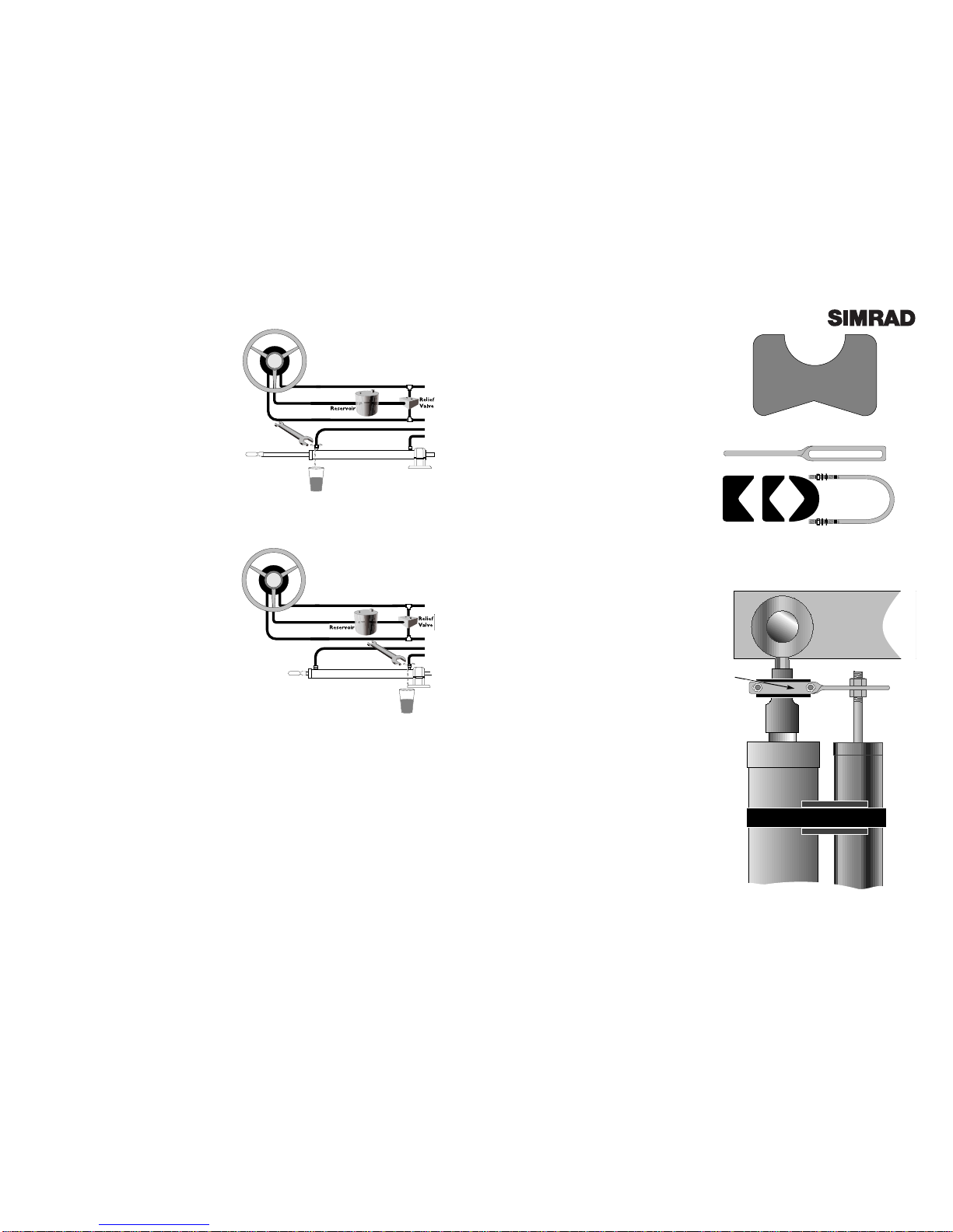
7. Turn the helm clockwise until the ram is fully
extended.
8. Open the bleed valve on the ram cylinder
nearest to the extended ram. If there are no
bleed valves fitted to the cylinder, loosen the
nut connecting the hydraulic hose to the cylin-
der to allow the air to escape. Do not com-
pletely undo the bleed valve or nut.
9. Holding the ram to stop it retracting into the
cylinder, turn the helm anti-clockwise until a
steady stream of oil comes out of the bleeder
with no air bubbles (Fig 4.5). Drain at least 1⁄2
litre (1 pint) of oil to ensure all air is purged
from the system. Retighten the bleed valve.
10. Keep the reservoir/helm unit filled up as oil
is pushed down into the system. Never allow
the oil level to drop below the rotor which
can be seen through the top filler hole in the
helm pump.
11. When all the air has been bled from the
lines, keep hold of the ram and slowly turn the
helm while tightening the bleed valve/nut.
12. Release ram and continue to turn the helm
counter-clockwise until the ram is fully retracted.
13. Open the bleed valve/hose nut on the
opposite end of the cylinder.
14. Holding the ram to stop it extending from
the cylinder, turn the helm clockwise until a
steady stream of oil comes out of the bleeder
with no air bubbles (Fig 4.6). Drain at least 1⁄2
litre (1 pint) of oil to ensure all air is purged
from the system. Retighten the bleed valve.
15. Keep the reservoir/helm unit filled up as oil
is pushed down into the system, taking care
that the oil level never drops below the rotor
which can be seen through the top filler hole in
the helm pump.
16. When all the air has been bled from the
lines, keep hold of the ram and slowly turn the
helm while tightening the bleed valve/nut.
17. Maintain the helm or reservoir at the indi-
cated fill line.
18. Check every joint and tube for leaks.
19. Fasten all tubing down to prevent fracture
due to vibration.
20. The manufacturer’s instructions should give
details of the correct number of turns lock to
lock when the system is properly bled. An
excessive number of turns indicates that there is
still air in the system.
Fig 4.5 - Bleeding starboard hydraulic line
Fig 4.6 - Bleeding port hydraulic line

Page 19Page 18
voir is kept topped up while doing this. NOTE
- Running the pump dry for more than a few
seconds can damage it. The hoses running to
the pump must be primed by following steps
6 to 9.
13. After completing the cycle with each helm
position to the lowest position (including the
SRP12 pump) loosen the bleed valves (or the
hose fittings if there are no bleed valves) on the
ram cylinder one at a time, allowing air to bleed
out until a steady stream of oil comes out of the
bleeder with no air bubbles. Drain at least 1⁄2litre
(1 pint) of oil to ensure all air is purged from the
system. Retighten the bleed valve.
14. Check the reservoir level. If it is less than
half full, depressurise the system, remove the
filler cap and top up the oil level. Pressurise the
system until the manufacturer’s recommended
pressure is reached.
15. Repeat steps 10 to 14, turning each helm in
the opposite direction.
16. Retighten the two relief valve screws.
17. Turn one of the helms hard over.
18. Open the bleed valve/fitting on the ram
cylinder at the end that the ram is extended
from. Bleed until there is a steady stream of oil
with no air bubbles (Fig 4.9). Retighten the
bleed valve.
19. Turn the helm hard over in the opposite
direction. Repeat step 18, opening the opposite
bleed valve this time (Fig 4.10).
20. Check the reservoir fluid level - leave reser-
voir 1⁄2to 2⁄3full.
21. Pressurise the system until the manufactur-
er’s recommended pressure is reached.
22. The manufacturer’s instructions should
give details of the correct number of turns lock
to lock when the system is properly bled. An
excessive number of turns indicates that there is
still air in the system.
Fig 4.9 - Bleeding first hydraulic line
Fig 4.10 - Bleeding second hydraulic line
Fig 4.13 - Ram mounting using fixing kit
4.3 Linear Feedback Unit SLF12
The Linear Feedback Unit SLF12 measures the
rudder position and can be installed on most
types of boat, including I/O or Outboard dri-
ves. It is important that the SLF12 is properly
installed with the maximum possible stroke
(minimum 150mm [6.0 in]), or it will not give an
accurate reading.
The SLF12 is mounted onto the hydraulic ram
cylinder using two mounting saddles (Fig 4.11).
Make sure that the maximum stroke of the
hydraulic ram is less than the 300 mm (12.0 in)
maximum stroke of the SLF12. The saddles
support the SLF12 body, and can then be posi-
tioned on the back of the ram cylinder. Check
that the SLF12 and ram are exactly parallel.
Use the cable ties supplied to secure the SLF12
and saddles onto the ram.
The SLF12 rod is attached to the ram using the
fixing kit supplied (Fig 4.12). Fit the U-bolt and
bracket to the ram, checking that it will not
interfere with the movement of the ram at any
point of steering. Rotate the assembly until the
SLF12 rod can be fixed to the slot in the bracket
using the two nuts supplied (Fig 4.13) Refer to
section 6.3 before tightening the nuts.
When satisfied with the positioning, tighten the
U-Bolt nuts fully, and then turn the helm hard
over from lock to lock, checking that the SLF12
rod does not bend at any time - this means that
the SLF12 is not exactly parallel to the ram, and
should be adjusted accordingly.
If the SLF12 cannot be fixed to the ram as
described, an accessory kit is available separate-
ly (part LFK500) which can be ordered through
your local Simrad agent. This contains a sepa-
rate mounting foot and balljoint assembly for
the end of the feedback rod, allowing the SLF12
to be independently fixed to the rudder arm.
• Do not fix the SLF12 directly to the rudder
arm if it is attached to the ram using the
mounting saddles, as the feedback rod will
bend when the rudder is at full lock.
• If connecting to a Teleflex HC5345 steering
cylinder the optional LFKSeastar kit should
be ordered.
FIg 4.11 - Mounting saddles (x 2)
Fig 4.12 - Fixing kit
Rudder Arm
Ram Cylinder
Cable Tie
SLF12
Fixing
Kit

Page 21
4.4 Fitting Control Unit SHC14
The SHC14 controller is supplied with a cradle
that can be screwed to a convenient bulkhead
using the supplied self-tapping screws. Drill
2.5mm (0.1 in) pilot holes for the screws.
• If fitting to glassfibre (GRP) countersink the
holes before screwing in to avoid splitting the
gelcoat.
The SHC14 is fitted with a coiled cable ending
in a four-pin plug. This connects to the autopi-
lot via a weatherproof socket assembly and
junction box.
• Fit the bulkhead socket to a vertical surface to
prevent standing water gathering around or in
the socket. Always fit the weather cap when the
remote is not plugged in.
To fit the socket to the dash, a 25mm (1 in) hole
will need to be drilled for the socket, which is
fixed using the four self-tapping screws provid-
ed with the socket assembly. Drill 2mm (0.1 in)
pilot holes for the screws.
• Again, to avoid splitting the gelcoat if fitting to
GRP, countersink the holes before screwing in.
4.5 Fitting Compass Unit SHS12
The compass should be positioned as close to
the centreline of the boat as possible (Fig 4.15),
in one of four possible orientations (see section
6.2). If the boat is GRP or wooden, the compass
can be mounted below deck, but must be at
least 1m (3 ft) away from any metallic objects
such as stereo speakers, heating units etc.
• If the boat has a metal hull (this includes fer-
rocement), the compass must be mounted
above decks on a mast or pole between one and
two metres (3 to 7 feet) above deck.
When mounting, make sure that the compass is
the right way up and is level. The compass unit
can be screwed to a vertical bulkhead using the
two No.6 x 3/4in self tapping screws provided. If
screwing into GRP, drill pilot holes and coun-
tersink them properly, which will stop the gel-
coat splitting when the screws are tightened.
Fig 4.15 - Mounting compass unit
BOTTOM
VIEW
SIDE
VIEW
BOW
BOW
Page 20
Fig 4.14 - Connecting control unit
Length of
Cable Run
Under 5M
(16.6Ft)
5-10M
(33.3Ft)
Cross Section
Area
2.5mm2
4mm2
Conductor
Type
50/0.25
56/0.3
AWG
13
12
Fig 4.17 - Cable selection table
Fig 4.16 - Mounting Course Computer
4.6 Fitting Course Computer SCP12
Locate the course computer in a moisture, heat
and vibration free area, somewhere between the
boat’s power source and the pump to minimise
power cable lengths.
• The SCP12 should be mounted vertically with
the cooling fin uppermost, and be easily acces-
sible once installed.
The unit is held in place using three No.6 x 1 in
self tapping screws. To access the mounting
holes, remove the terminal cover by loosening
the three screws holding it in place. Drill and
countersink three pilot holes in the indicated
positions if screwing to GRP (Fig 4.16).
4.7 Electrical Installation
• The SCP12 should be connected to the boat’s
battery via the main switch panel with a prop-
erly rated breaker or fuse and switch. It will be
much easier to configure the rudder limits if the
switch is close to the SHC14 control.
• All AP14H components wire directly to the
SCP12 course computer. The terminal bay is
clearly labelled, and each terminal block has a
specific cable channel.
• It is important that the correct diameter
cable is used to supply the 12v power to the
SCP12, depending on the length of run nec-
essary (Fig 4.17). For this reason, the SCP12
should be fitted as close to the power supply
and pump as possible.
The SLF12, SHC14 and SHS12 are all connected
to the course computer using three conductor
cables (red, white and black). Each cable is con-
nected to the marked terminal in the connection
bay (Fig 4.18 - over). For good connections, wire
ends should be tinned if the cables are shortened.
Poor connections will impair performance.
• The cables should be kept away from cables
which carry radio or pulsed signals (1m / 3 Ft
minimum distance is recommended).
Each cable should then be led through the
appropriate cable channel, which will hold the
cables firmly in position when the terminal
cover is replaced.
TOP VIEW
SIDE VIEW

Fig 4.20 - Connecting using NMEA interface :
no Common (–) wire
NMEA OUT
D ATA ( + )
4.8 Interfacing via NMEA
The AP14 includes a built in NMEA0183 inter-
face so GPS, Loran and Chart Plotters can be
connected directly to it. This allows the Nav
Mode (Steer to GPS) function to be used.
To interface with the AP14, the NMEA OUT
connections of the equipment should be wired
to the respective NMEAIN Data and Common
(COM) terminals of the AP14 course comput-
er (Fig 4.19).
• Some manufacturers may refer to the con-
nections as NMEA OUT + and –instead of
NMEA Data and Common.
• Certain equipment may have connections
marked NMEA IN. Do not use these.
• If the equipment does not have a NMEA
Common (or –) connection, the NMEA
Common terminal of the SCP12 course com-
puter should be connected to ground by link-
ing it to the BATT – terminal (Fig 4.20).
• If the vessel has more than one battery bank,
when connecting the AP14 to the power supply
always check that the pilot and the receiver are
not connected to a different battery bank. This
is to avoid a possible voltage drop between the
interfaced equipment which would render the
equipment inoperative.
• The receiver must be running an active route
or waypoint for the Nav Mode function to
operate.
• While any NMEA0183 compatible receivers
should interface with the AP14, Simrad cannot
guarantee operation with other manufacturer’s
equipment, as the Nav Mode function is
dependant on specific NMEA0183 sentences of
the correct format being available (see section
7.3). Read the relevant section in the receiver’s
manual before attempting to interface the AP14
with this equipment. If necessary, contact the
manufacturer’s technical support department
or speak to a qualified technical dealer.
Fig 4.19 - Connecting using NMEA interface
NMEA OUT
D ATA ( + )
NMEA OUT
COMMON (–)
Page 23
+–
+–
To 12v + DC
To 0 v
NMEA0183 In
To Control Unit SHC14
To Compass Unit SHS12
To Feedback Unit SLF12
To Pump
Fig 4.18 - Course Computer SCP12 connections
Page 22

Page 25
5 Installation - AP14R
Section 5 covers the installation of the AP14R
Rotary drive version only. Please refer to sec-
tion 4 for AP14H Hydraulic version installa-
tion instructions.
5.1 Drive Installation
The SRD12 drive is a combined steering helm
and gearbox which completely replaces the
existing steering helm unit (Fig 5.1).
The drive unit is based on the popular Morse
CMD290 helm unit and is directly compatible
with this.
• The drive can also be fitted onto boats using
other systems including Teleflex, Uflex, Acco,
Mercury, Volvo Penta, Detmar, rack and pinion
etc. Depending on the system, it may be neces-
sary to fit an adaptor or change the cable and
dashboard bezel kit. Refer to the table below
for more details. All codes quoted are Morse
part numbers and are available from Morse
suppliers.
Fig 5.1 - SRD12 totally replaces helm unit
AP14R Compatibility Guide
Helm System Cable Bezel Kit Needed Cable Needed
Adaptor Needed 20º 90º
Morse CMD290 NO NO NO NO
Morse CMD250 NO 308561 308559 NO
Morse CMD200 rack & pinion NO 306527 306504 304411-xx*
Morse CMD2 NO 306527 306504 304411-xx*
Teleflex Safe-T / Big-T 300959 308561 308559 NO
Teleflex rack & pinion NO 308527 308504 304411-xx*
Teleflex Non-feedback NO 308561 308559 NO
Teleflex Quick Connect Safe-T NO 308561 308559 NO
Volvo NO 308561 308559 NO
Detmar Square or Round Rack NO 308561 308559 304411-xx*
ACCO / Mercury NO 308561 308559 304411-xx*
Wheel must also be changed for one
with a 18.75mm (3⁄4in) shaft
*xx = length in inches (1 inch = 25mm)x
Page 24
To be able to fit the AP14R to the boat, the fol-
lowing basic requirements must be met -
1. The boat must have at least one single cable
steering helm. Dual cable systems, which are
for high performance boats or boats over 11m
(35 Ft) cannot be adapted for the AP14R.
However, the AP14R can be fitted to boats with
two steering positions, providing that one has a
single cable helm.
2. There must be a minimum of 250mm (10.0 in)
clearance behind the dashboard for the drive
unit to fit (Fig 5.2).
• If the boat has a Morse CMD290 helm system
fitted, it can be directly replaced with the
SRD12 drive unit.
• Other rotary helm units may need a cable
adaptor, dashboard bezel kit, or the whole
steering cable may need to be replaced (see
compatibility guide, page 21).
• On boats with rack and pinion steering it will
be necessary to change the steering cable.
• ACCO or Mercury steering systems will also
need to change the steering wheel for one with
a 18.75mm (3⁄4in) shaft aperture.
5.2 Removing Existing Steering Helm
To remove the existing steering helm, take the
steering wheel off then unbolt and remove the
helm unit. If it is a rack and pinion system then
the rack will need to be unbolted from the pin-
ion before it can be removed.
Check that there is enough clearance behind the
dashboard for the drive unit before installing -
obstructions such as electrical wiring and throt-
tle cables may need to be re-routed.
If a bezel kit is needed, note the angle that the
helm is mounted to the dashboard. Bezel kits
are available either in the standard 90º configu-
ration, or 20º if the helm is fitted at an angle to
the dashboard (Fig 5.3). Note that tilting wheel
systems use the existing (original) bezel kit.
Fig 5.3 - Bezel kits available
90º
20º
Fig 5.2 - Minimum clearance required
250mm (10.0 in)

Page 27
• Use the bezel plate as a template to mark the
mounting holes that will need to be drilled.
• Take care when drilling not to damage or
sever any wiring or cables behind the dash-
board - if necessary tape these out of the way
temporarily until the holes have been drilled.
• If it is necessary to enlarge the existing steer-
ing shaft hole in the dashboard for the drive
unit, use a piece of wood clamped over the hole
as a guide for the hole saw. This will ensure
that the hole is cut accurately and the bit does
not jump while drilling, which could scratch or
damage the dashboard. Exercise caution while
doing this.
Fit the bezel plate to the dashboard, but do not
fit the plastic cover at this point.
Remove the steering cable from the helm unit
by unfastening the retaining bolt at the cable
entry and exit ports. Pull the cable outer away
from the helm unit (Fig 5.4), then the cable
inside can be wound out by turning the steering
shaft (it may help if the wheel is refitted).
• Make a careful note of how the helm unit is
fitted to the dash and which side of the helm
that the cable is inserted - if this is refitted incor-
rectly the steering will work in reverse.
If the steering cable is not compatible with the
SRD12 drive unit it will need to be changed for
a Morse cable, which can be ordered from any
Morse stockist. The part number of the cable is
304411-xx, where xx refers to the length of the
cable required in inches (1 inch = 25mm).
See section 5.4 for advice on changing the cable.
5.3 Fitting SRD12 Drive Unit
Before winding the cable into the SRD12 drive
unit, apply a thin coat of Teflon grease to the
exposed section of the cable. Insert the plastic
take-up tube into the exit port and refit the
retaining bolt to hold it in place (Fig 5.5).
If required, fit the cable adaptor to the steering
cable to enable it to fit to the drive unit.
Insert the steering cable into the entry port of
Fig 5.4 - Remove retaining bolts to allow cable outer
to be disconnected
Fig 5.5 - Fit take-up tube to the exit port and replace
retaining bolt
Page 26
the drive unit and wind it in by turning the
steering shaft. The cable should wind into the
drive unit and emerge through the exit port into
the take-up tube (Fig 5.6). Push the cable outer
retainer into the entry port and refit the retain-
ing bolt to hold it in place.
Position the drive unit behind the dashboard,
and bolt it to the bezel plate. Fit the plastic
cover over the bezel plate (this should simply
snap into place). Secure the bezel retaining ring
to the drive shaft, insert the locating key (or
“woodruff key”) into the recess on the steering
shaft and refit the steering wheel (Fig 5.7).
• Depending on the layout of the dashboard and
steering system, it may be easier to fit the drive
unit to the dashboard first, then insert the cable.
Rotate the wheel fully from lock to lock to check
that the steering works smoothly across its full
range and that it is steering in the right direc-
tion. If the rudder moves in the opposite direc-
tion to the wheel, the cable has been inserted
into the drive unit the wrong way and needs to
be inserted in the other port - swap the cable
and take-up tube over.
5.4 Changing the Steering Cable
The accessibility of the steering cable run will
depend on the size of the boat - on smaller
powerboats the cable is usually easily accessi-
ble, but larger boats may run the cable through
ducts that are more difficult to access.
• Changing the cable will be easier if a mouse
(or “tag line”) is attached to the end of the exist-
ing cable before it is removed. This can be used
to pull the new cable through.
• Use a strong line for the mouse that is not like-
ly to snap easily, but is thin enough to pass
down the duct behind the cable.
• Tie the mouse securely to the cable and use
tape to reinforce the joint. Pull the cable
through from the rudder end while feeding the
mouse line from the steering end. When the old
cable has been completely removed, attach the
mouse to the new cable and use it to pull it back
through from the rudder end.
Fig 5.6 - Wind steering cable into helm
Fig 5.7 - Fitting drive to dashboard and attaching
wheel
Locating
(“Woodruff”) key

Page 29
Attach the new cable to the steering arm of the
boat by pulling out the cotter pin and clevis pin
to release the old steering shaft and replacing it
with the new steering shaft. Line up the shaft
with the steering arm by turning the steering
wheel and re-insert the cotter and clevis pins.
5.5 Fitting Control Unit SHC14
The SHC14 controller is supplied with a cradle
that can be screwed to a convenient bulkhead
using the supplied self-tapping screws. Drill
2.5mm (0.1 in) pilot holes for the screws.
• If fitting to glassfibre (GRP) countersink the
holes before screwing in to avoid splitting the
gelcoat.
The SHC14 is fitted with a coiled cable ending
in a four-pin plug. This connects to the autopi-
lot via a weatherproof socket assembly and
junction box.
• Fit the bulkhead socket to a vertical surface to
prevent standing water gathering around or in
the socket. Always fit the weather cap when the
remote is not plugged in.
To fit the socket to the dash, a 25mm (1 in) hole
will need to be drilled for the socket, which is
fixed using the four self-tapping screws provid-
ed with the socket assembly. Drill 2mm (0.1 in)
pilot holes for the screws.
• Again, to avoid splitting the gelcoat if fitting to
GRP, countersink the holes before screwing in.
Page 28
Fig 5.8 - Connecting control unit
5.6 Fitting Compass Unit SHS12
The compass should be positioned as close to
the centreline of the boat as possible (Fig 5.9), in
one of four possible orientations (see section
6.2). If the boat is GRP or wooden, the compass
can be mounted below deck, but must be at
least 1m (3 ft) away from any metallic objects
such as stereo speakers, heating units etc.
• If the boat has a metal hull (this includes fer-
rocement), the compass must be mounted
above decks on a mast or pole between one and
two metres (3 to 7 feet) above deck.
When mounting, make sure that the compass is
the right way up and is level. The compass unit
can be screwed to a vertical bulkhead using the
two No.6 x 3/4in self tapping screws provided. If
screwing into GRP, drill pilot holes and coun-
tersink them properly, which will stop the gel-
coat splitting when the screws are tightened.
5.7 Electrical Installation
• The AP14R should be connected to the boat’s
battery via the main switch panel with a proper-
ly rated breaker or fuse and switch.
• The AP14R operates from a 12v DC supply.
Power is supplied to the system via the two
core cable from the SRD12 drive unit. Brown
is 12v+, Blue is 0v.
• If the power cable needs to be extended, the
correct diameter cable should be used,
depending on the length of run (Fig 5.10). For
this reason, it is recommended that any addi-
tional cable runs be as short as possible.
The SHC14 control unit, SHS12 compass and
SRD12 drive unit are wired together using the
SJB12 junction box supplied. All three cables
have the same core colours - Red, Black and
White, and the terminals in the junction box
are clearly marked (Fig 5.11 - over).
• For good connections, all wire ends should be
tinned if the cables are shortened. Poor connec-
tions will impair the performance of the pilot.
• The cables should be kept away from cables
which carry radio or pulsed signals (1m / 3 Ft
minimum distance is recommended).
Length of
Cable Run
Under 5M
(16.6Ft)
5-10M
(33.3Ft)
Cross Section
Area
2.5mm2
4mm2
Conductor
Type
50/0.25
56/0.3
AWG
13
12
Fig 5.10 - Cable selection table
Fig 5.9 - Mounting compass unit
BOTTOM
VIEW
SIDE
VIEW
BOW
BOW

RED
NMEA OUT
D ATA ( + )
Fig 5.13 - Connecting using NMEA interface :
no Common (–) wire
5.8 Interfacing via NMEA
The AP14 includes an inbuilt NMEA0183 inter-
face so GPS, Loran and Chart Plotters can be
connected directly to it. This allows the Nav
Mode (Steer to GPS) function to be used.
To interface with the AP14, the NMEA OUT
connections of the equipment should be wired
to the respective NMEA IN Data and Common
(COM) cores of the NMEAwire from the SRD12
drive unit (Fig 5.12).
NMEA Data - RED
NMEA Common - BLUE
• Some manufacturers may refer to the connec-
tions as NMEA OUT +and –instead of NMEA
Data and Common.
• Certain equipment may have connections
marked NMEA IN. Do not use these.
• If the equipment does not have a NMEA
Common (or –) connection, the NMEA
Common terminal of the SCP12 course com-
puter should be connected to ground by link-
ing it to the BATT – terminal (Fig 5.13).
• If the vessel has more than one battery bank,
when connecting the AP14 to the power supply
always check that the pilot and the receiver are
not connected to a different battery bank. This
is to avoid a possible voltage drop between the
interfaced equipment which would render the
equipment inoperative.
• The receiver must be running an active route or
waypoint for the Nav Mode function to operate.
• While any NMEA0183 compatible receivers
should interface with the AP14, Simrad cannot
guarantee operation with other manufacturer’s
equipment, as the Nav Mode function is
dependant on specific NMEA0183 sentences of
the correct format being available (see section
7.3). Read the relevant section in the receiver’s
manual before attempting to interface the AP14
with this equipment. If necessary, contact the
manufacturer’s technical support department
or speak to a qualified technical dealer.
Fig 5.12 - Connecting using NMEA interface
BLUE
NMEA OUT
COMMON (–) 0v
RED
NMEA OUT
D ATA ( + )
BLUE
NMEA OUT
COMMON (–)
Page 31Page 30
SHC14 Control Unit
SHS12 Compass
12v DC
NMEA0183 In
Brown / Blue
Red / Black / White
Red / Blue
Fig 5.11 - AP14R electrical installation
SRD12 Drive Unit
SJB12 Junction Box

Page 33
6 Commissioning
6.1 Commissioning Checks
After installation has been completed, the following checks should be made before use -
1. Installation check - ensuring that the installation of all the components in the system is mechan-
ically and electrically correct.
2. Seatrial - Auto compass calibration. The pilot should be set up for optimum course keeping
ability. If a navigational receiver is interfaced with the pilot, Nav Mode should also be tested.
6.1.1 Installation Check
CABLING
1. Are all the connections secure?
2. Does all wiring meet recommended lengths and sizes for the current/voltage?
3. Does the input power line have the correctly rated fuse or circuit breaker?
4. Where possible, are the cables run away from existing cables which carry radio frequency
or pulsed signals? (1m / 3 Ft distance is recommended).
5. Are cables neatly tied or clamped to prevent friction damage? (Ties every 0.5m / 1.5 Ft
intervals recommended minimum).
6. Are all wire ends tinned?
COURSE COMPUTER SCP12 (AP14H ONLY)
1. Is the Course Computer in a dry location away from excessive heat and vibration?
2. Is the Course Computer mounted on a vertical surface, with the cooling fin uppermost?
3. Is the Course Computer securely attached to a permanent structure?
4. Are all the cables properly fed through the cable clamp channels?
LINEAR FEEDBACK UNIT SLF12 (AP14H ONLY)
1. Has the unit been securely attached to the hydraulic ram of the boat using the supplied
mounting saddles?
2. Is the full stroke of the SLF12 between 150mm and 300mm (6.0in to 12.0in)?
3. Is the SLF12 correctly aligned with the rudder arm?
4. Has it been fitted so that the rod does not bend or distort at any point of steering?
5. When driven hard over from lock to lock, is the SLF12 free from any obstructions?
COMPASS SHS12
1. Has the compass been mounted the correct way up and is it level?
2. Has the compass been mounted in a position away from ferrous materials, loudspeakers,
heavy current carrying cables or other magnetic/electronic equipment to avoid deviation?
3. Has the compass been mounted as near as possible to the centrepoint of the boat to min-
imise heel angle?
HYDRAULIC PUMP (AP14H ONLY)
1. Have the correct fittings been used?
2. Has return line (R) been fitted from the pilot pump ?
3. Are check valves fitted if needed ?
4. Has the system been correctly bled of air ?
5. Is the tubing to the pump high pressure flexible material to reduce vibration?
Page 32
Fig 6.2 - Adjusting compass bearing
6.2 Compass Orientation
The SHS12 compass can be mounted pointing
four different ways - 0º, 90º, 180º or 270º to the
bow (Fig 6.1).
• The factory preset is 0º (pointing forward). If
the compass is mounted pointing any other
way, this must be programmed in before using
the pilot.
Press and hold Set until the controller beeps
twice.
Press Set again - the display will show the cur-
rent offset.
Press to adjust the offset in 90º steps to port.
Press to adjust the offset in 90º steps to star-
board - 90º, 180º, 270º.
• If no key is pressed within 5 seconds, the con-
troller will return to the main display and the
orientation currently entered will be set.
6.3 Compass Adjustment
The bearing shown on the AP14 display can be
adjusted by ±15º so that it matches the boat’s
magnetic compass, or a known heading.
• This procedure should be performed after the
compass has been orientated (see section 6.2
above).
Press and hold the Set key. The controller will
beep twice and the display will show ADJUST
along with the current bearing detected by the
SHS12 fluxgate compass.
Use the and keys to adjust the displayed
bearing until it matches the boat’s magnetic
compass, or known heading (Fig 6.2).
• If no key is pressed within 5 seconds, the con-
troller will return to the main display and the
bearing entered will be set.
• Note that the bearing can be adjusted by a
maximum of ±15º from the original. If the error
is greater than 15º, check that the SHS12 com-
pass is not receiving interference from nearby
metallic, magnetic or electrical objects.
Fig 6.1 - Compass orientation
0º (No flashes)
180º (2 flashes)
90º (3 flashes)
270º (1 flash)
BOW
BULKHEAD
Pressed & held

Page 35Page 34
Fig 6.5 - Rate of turn too slow
6.5 Seatrial / Compass Calibration
Before using the AP14, the compass must be calibrated
to compensate for any magnetic deviation caused by fer-
rous or magnetic objects surrounding it on the boat, such
as cockpit speakers etc.
1. With the boat motoring along slowly (2-3 knots) in
calm conditions press the key a number of times (or
manually steer) to induce a slow clockwise rotation of the
boat (approx 3º/sec).
2. Press and hold Gain, followed by the and keys
simultaneously to enter Auto Compass Calibration Mode
(Fig 6.4) The display shows the heading, and the bottom
line will show CAL.
3. Allow the boat to turn through a minimum of 11⁄4turns
(450º) in approximately 2 1⁄2minutes, during which time
the fluxgate compass will automatically calibrate itself.
4. If the rate of turn is too high, the display will flash arrows pointing to Port indicating decrease the
angle of turn - press . If the rate or turn or boat speed is too slow the display will flash arrows
pointing to Starboard indicating increase the angle of turn (Fig 6.5) - press .
• It is recommended that the calibration is restarted if the Port arrows are shown more than twice.
A sequence of 4 beeps means that the calibration has been successful, and the AP14 will return to
Standby Mode.
• If after about four minutes the compass has not calibrated, an alarm will sound. Repeat the above
procedure, following the directions carefully. If the compass will still not calibrate then it is usual-
ly because the deviation being detected is too great, which may be due to the compass being too
close to a metallic or magnetic object (minimum safe distance - 1m [3 Ft]). Move the compass to a
position as close to the ideal centreline location as possible, but away from speakers, metallic super-
structure etc. Repeat the above procedure.
• This should only need to be done once when the autopilot is first commissioned, unless the com-
pass is changed, repaired, relocated or if any metallic objects have been installed or removed near
to the compass since it was calibrated. In the interests of accurate performance, always bear in
mind the location of the compass when installing any metallic objects on the boat. If in any doubt,
recalibrate the compass as shown above.
After calibrating the compass perform the following procedure -
1. Hold the course steady for 5-10 seconds.
2. Press Auto to engage the autopilot and lock onto the heading - in calm conditions a constant
heading should be held.
3. Alter course to Port and Starboard - the course change should be smooth without any sign of
overshooting.
4. Look back at the wake of the boat to get an indication of the steering performance over a dis-
tance of at least 3km (2 Miles). If there is any evidence of snaking or “S-ing”, try decreasing the
Gain setting (see section 3.1).
5. If a GPS is connected , the Nav Mode function should be tested over a longer distance.
Fig 6.4 - Auto Compass Calibration
POWER ON
Fig 6.3 - Setting rudder limits
6.4 Setting Rudder Limits (AP14H only)
This two-stage procedure is used to -
• Define the maximum limits of the SLF12 pushrod stroke.
• Define the endstop and midstroke position of the rudder.
This data is permanently stored, so it will only be neces-
sary to repeat this procedure if the SCP12 is replaced or
the SLF12 is replaced/repositioned.
1. Turn the power to the pilot off at the breaker (or
switch). Press and hold the and keys while switch-
ing the power on.
2. The display will show CAL and PORT (Fig 6.3). If this
display is not shown, repeat step 1, holding the and
buttons down firmly.
3. Disconnect the SLF12 rod from the ram and pull it fully
from the feedback body (the rod is not physically
attached to the SLF12 and can be removed easily).
4. Slide the rod all the way into the feedback body as far
as it will go, then reattach the rod to the rudder. This sets
the maximum limits of the SLF12
5. Turn the helm hard over to Port, then back it off 1⁄8th of
a turn. Push the key once, and the controller will beep,
showing STBD on the display.
6. Turn the wheel hard over to Starboard, then back it off
1⁄8th of a turn. Push once - the controller will beep and
show CENTRE on the display.
7. Turn the helm to the midships position and press
Gain. The pump will drive the rudder briefly to test
the limits entered. If the rudder limits are accepted, the
controller will beep four times and the display will show
OKAY, otherwise it will sound a continuous alarm and
show FAIL, meaning that the calibration has failed -
repeat the above steps carefully.
• If the calibration still fails, this may indicate that the
hard over rudder position is beyond the sensing range of
the SLF12 or the system has not been bled properly and
the pump is airlocked. Try repositioning the SLF12 so
that the stroke is within the defined parameters (see sec-
tion 4.3), bleed the system if necessary and repeat the
above procedure.
Note that the pilot will not enter Auto mode until the
rudder limits have been set.

7.4 Fault Finding
Symptom
Pilot will not enter Auto mode.
Autopilot drops back into
Standby Mode.
Cannot select Nav Mode
Autopilot will not allow rudder
travel limits to be set*.
Autopilot does not maintain an
accurate course in Auto Mode.
Compass will not auto calibrate
Boat’s course is unstable when
in Auto mode.
Probable Cause
Rudder limits not entered*.
Rudder limits configuration
failed*.
Faulty connection to SLF12*
Faulty connection to SHS12.
Fault with SCP12* / SRD12†.
Low supply voltage to Drive
Unit or Course Computer*.
Navigational data not avail-
able.
Incorrect NMEAformat or sen-
tences are being transmitted.
Destination not programmed
in navigator.
Power cable gauge too small.
SLF12 incorrectly wired or
installed.
Pump not primed or airlocked
Buttons not pressed properly
SHS12 compass has not been
calibrated.
SHS12 compass is encounter-
ing magnetic interference.
• If the boat’s magnetic
compass is being used as a ref-
erence, it is more likely that
this is inaccurate unless it has
being recently swung.
Turn rate too fast/slow
Conditions too rough
Deviation detected is too large
Gain setting is incorrect for
boat’s speed or type.
Remedy
Enter rudder limits* (see 6.3)
Check all connections.
Replace fuse.
Check battery charge.
Check all electrical connec-
tions and supply cables.
Check NMEA connections.
Refer to section 7.3 for correct
NMEA0183 sentence formats.
Check recommended cable
sizes (Fig 4.17)
Check SRP12 & SLF12 wiring
and installation.
Prime pump & bleed system.
Refer to section 6.4 to calibrate
the compass to compensate for
magnetic deviation.
Check area around SHS12 for
magnetic objects (loudspeak-
ers, heavy current carrying
cables etc). Minimum com-
pass safe distance is 1m (3 Ft).
Check course against other
reference (handbearing com-
pass etc) and swing boat’s
compass if necessary.
Flashing LEDs above
Port/Starboard keys indicate
if turn rate is too fast or slow.
Calibration should be attempt-
ed in calm conditions
Check area around compass
for metallic objects/speakers
etc (min safe distance - 1m/3ft)
Adjust Gain to suit boat’s
speed: Low Speed=High Gain
High Speed=Low Gain
* - AP14H only † – AP14R only
Page 36 Page 37
7 Appendix
7.1 Advice On Operation
• When making course changes, be aware of the effect of a large course change on the boat, espe-
cially when travelling at high speed - the AP14 will respond very quickly to any instructions, so it
is advisable to reduce speed before changing course. This should particularly be remembered
when approaching a waypoint in Nav Mode - pressing Nav to head for the next waypoint could
result in a sudden and severe course change. This is one of the reasons that a constant vigil and
awareness of the situation must be maintained (see warning below).
• The Gain setting is critical on a high speed vessel like a power boat, because it affects the reac-
tion speed of the autopilot. As you become more familiar with the operation of the AP14 and how
your own boat handles, it should be possible to tailor the Gain settings to suit the speed of the boat
and the conditions it is cruising under.
7.2 Warning
The AP14 is a highly advanced autopilot, and a valuable aid to enjoyable cruising. However, it
would be a mistake to become complacent. Like all electronic navigational equipment, it is an aid
to navigation and should not be used as a substitute for conventional navigational practice.
Remember - Maritime Law* requires that you keep a good look out at all times.
7.3 NMEA Sentences Received
The NMEA0183 information required for full functionality while in Nav Mode is as follows -
Cross track error
Bearing to destination waypoint
Arrival at waypoint indication
This information is extracted from the following NMEA0183 sentences -
XTE Cross Track Error
BWC Bearing & Distance To Destination Waypoint (Great Circle)
BWR Bearing & Distance To Destination Waypoint (Rhumb Line)
APA Cross Track Error, Bearing To Destination Waypoint and Arrival At Waypoint
APB Cross Track Error, Bearing To Destination Waypoint and Arrival At Waypoint
RMA Boat Speed
RMB Cross Track Error, Bearing, Distance and Arrival At Arrival Waypoint
RMC Boat Speed
NOTE - The Cross Track Error (XTE) information has a maximum value of 1.27 Nautical Miles. If
the XTE exceeds this while using Nav Mode, the AP14 will sound an alarm, exit Nav Mode and
return to Compass Auto Mode.
*IMO International Regulations for Preventing Collisions at Sea, Part B Rule 5 (1972)

Page 39
In the event of the AP14H failing, the LED located under the terminal bay cover of the SCP12 Course
Computer can be used to identify the potential source of the problem -
Flashes Diagnosis Fault Location
2Invalid rudder feedback reading from SLF12 SLF12
4Current limit exceeded SRP12, SCP12
5Control unit not connected SHC14
6No compass data received SHS12
7No compass/controls detected SHC14, SHS12, SCP12
8Rudder limits not set / calibration failed SLF12, SCP12
In the event of the AP14R failing, the LED located on the circuit board under the black cover of the
SRD12 Drive Unit can be used to identify the potential source of the problem -
Flashes Diagnosis Fault Location
5Control unit not connected SHC14
6No compass data received SHS12
7No compass/controls detected SHC14, SHS12, SRD12
8Compass calibration failed SRD12
Page 38
7.5 Optional Accessories
The following optional accessories for the
AP14H and AP14R are available from your
Simrad dealer. Please quote the correct part
number when ordering.
SCJ12
Additional Control
Unit +
Junction Box
SCJ14
Hand Controller +
Junction Box
LFK500
SLF12 Feedback Mounting Accessory Kit -
balljoint & universal joint mounting foot.
(for AP14H hydraulic drive option only)
LFKSeastar
Kit for mounting SLF12 (AP14H only) to
Teleflex HC5345 cylinders
Table of contents
Other Simrad Boating Equipment manuals
Popular Boating Equipment manuals by other brands

Wichard
Wichard ProFurl NEXE 5.0V12 installation manual

MINN KOTA
MINN KOTA i-Pilot Link Quick reference guide

Power-Pole
Power-Pole micro anchor installation manual

MotorGuide
MotorGuide BounceBuster Original owner's manual

Ultraflex
Ultraflex UC 81 Installation and maintenance manual

Made Engineered
Made Engineered Romar Leisure Furl furling boom owner's manual