manuals.online logo
Brands
  1. Home
  2. •
  3. Brands
  4. •
  5. Blagdon
  6. •
  7. Pond Pump
  8. •
  9. Blagdon Koi Air 25 Manual

Blagdon Koi Air 25 Manual

This manual suits for next models

2

Other Blagdon Pond Pump manuals

Blagdon AMPHIBIOUS Series Manual

Blagdon

Blagdon AMPHIBIOUS Series Manual

Blagdon Force hybrid 5000 User manual

Blagdon

Blagdon Force hybrid 5000 User manual

Blagdon MINIPOND 2000 User manual

Blagdon

Blagdon MINIPOND 2000 User manual

Blagdon Amphibious IQ Series User manual

Blagdon

Blagdon Amphibious IQ Series User manual

Blagdon Hydratech Torrent 3000 User manual

Blagdon

Blagdon Hydratech Torrent 3000 User manual

Blagdon inpond 5 in 1 3000 User manual

Blagdon

Blagdon inpond 5 in 1 3000 User manual

Blagdon 1057233 User manual

Blagdon

Blagdon 1057233 User manual

Popular Pond Pump manuals by other brands

Messner system-N 850 operating instructions

Messner

Messner system-N 850 operating instructions

Oase PondJet Eco operating instructions

Oase

Oase PondJet Eco operating instructions

Profi-pumpe Rügen operating instructions

Profi-pumpe

Profi-pumpe Rügen operating instructions

HEISSNER F540-00 Instructions for use

HEISSNER

HEISSNER F540-00 Instructions for use

Pond Technics POND AIR 600 manual

Pond Technics

Pond Technics POND AIR 600 manual

Tsurumi Pump AquascapePro 8-PN 5500 Instructions & maintenance

Tsurumi Pump

Tsurumi Pump AquascapePro 8-PN 5500 Instructions & maintenance

Pontec PondoMax Eco 1500 operating instructions

Pontec

Pontec PondoMax Eco 1500 operating instructions

TotalPond DD11210 quick start guide

TotalPond

TotalPond DD11210 quick start guide

esotec Siena LED operating manual

esotec

esotec Siena LED operating manual

Profi-pumpe Solar Aqua-Vital 9-UV-C operating instructions

Profi-pumpe

Profi-pumpe Solar Aqua-Vital 9-UV-C operating instructions

Oase AquaAir Eco 250 Commissioning

Oase

Oase AquaAir Eco 250 Commissioning

Fiap Aqua Active Profi manual

Fiap

Fiap Aqua Active Profi manual

Fiap Aqua Active Mini Set 1.000 instruction manual

Fiap

Fiap Aqua Active Mini Set 1.000 instruction manual

Oase AquaMax Eco Classic Series operating instructions

Oase

Oase AquaMax Eco Classic Series operating instructions

aquanique PP-2500 operating instructions

aquanique

aquanique PP-2500 operating instructions

Bermuda BER0364-P019C instruction manual

Bermuda

Bermuda BER0364-P019C instruction manual

fish mate 9000 instructions

fish mate

fish mate 9000 instructions

1A Profi Handels OASIS 501R-1 operating instructions

1A Profi Handels

1A Profi Handels OASIS 501R-1 operating instructions

manuals.online logo
manuals.online logoBrands
  • About & Mission
  • Contact us
  • Privacy Policy
  • Terms and Conditions

Copyright 2025 Manuals.Online. All Rights Reserved.

THE POND MASTERS
GUIDE TO
KOI AIR
25/50/65
Koi Air Instruction Leaflet 2.qxd 30/3/06 13:51 Page 1
THE POND MASTERS GUIDE TO
KOI AIR
25/50/65
Congratulations on buying a Blagdon Koi Air high output pond air pump.
Koi Air pumps have been specifically designed for water garden applications.
Pond aeration is an essential part of a successful pond. Koi Air pumps are
able to run numerous air stones at one time creating a healthy oxygen rich
pond that will benefit your fish and biological filter bacteria. Your Koi Air
pump is both cost effective to run being of a low wattage design, and can be
maintained with excellent value replaceable parts.
BENEFITS OF KOI AIR POND AERATION
Fish and other pond life require oxygen-rich water in order to remain healthy. Filter
bacteria, essential to the breakdown of highly toxic ammonia and nitrite, also require
oxygen to flourish and keep the pond free from the build up of toxic waste. Use of a
Blagdon Koi Air pump will dramatically increase the level of oxygen in the pond and
reduce carbon dioxide levels, thus aiding in preventing the pond from stagnating, by
injecting air into the water. Additionally, by placing air stones directly into the filter
chambers, beneficial bacteria, essential to the well being of a pond will be
encouraged to grow. This will improve greatly filter efficiency and fish health.
Aeration in the pond is especially important in warm weather, when water holds
much less oxygen, and at night when plants stop producing oxygen and start using it
up. Fish seen gulping at the surface or swimming lethargically may be showing signs
of lack of oxygen.
In winter, use a Koi Air pump to keep areas of the pond ice-free, thus preventing the
build up of toxic gases that can be fatal to fish and other aquatic life.
Oxygenation, provided by the use of a Koi Air pump, is essential when treating fish
diseases, as many treatments deplete oxygen from the water and sick fish require
higher levels of oxygen.
IMPORTANT
Please attach proof of purchase to this manual and keep in a safe place.
Koi Air Instruction Leaflet 2.qxd 30/3/06 13:51 Page 2
1. CONTENTS
Section No.
Benefits of Pond Aeration Inside front cover
Technical specifications and performance 1
Getting to know your Koi Air Pump 2
Parts descriptions / spares codes / exploded diagrams 2, 3, 4, 5
Installation 6
Electrical installation 6
Location 7
Connecting air line and air stones 7
Maintenance 8
Replacing the intake and outlet foams 8
Replacing the flapper valves Koi Air 25 9
Replacing the flapper valves Koi Air 50/65 9
Replacing the diaphragm Koi Air 25 10
Replacing the diaphragm Koi Air 50/65 11
Troubleshooting 12
Troubleshooting and maximising performance 12
Faults Problems Procedure Inside back cover
Consumer advice contact details Inside back cover
Returning faulty air pumps Inside back cover
Guarantee Inside back cover
Technical Specification and Performance
KOI AIR MODEL 25 50 65
Cable fitted 3M 3M 3M
Voltage 230 V 230 V 230 V
Hertz 50 Hz 50Hz 50 Hz
Wattage 18w 30w 42w
Maximum Flow 25ltr/min 50ltr/min 65ltr/min
Maximum Pressure 0.028mpa 0.032mpa 0.040mpa
Pumping Depth 2.2M 3.0M 3.5M
Number of air outlets 8 12 18
Koi Air Instruction Leaflet 2.qxd 30/3/06 13:51 Page 3
2. GETTING TO KNOW YOUR KOI AIR 25
No. Name of part
Code
1. Air filter cover
2. Intake foam seal (see No.3
for replacement)
3. Intake foam filter & intake
seal 1019880
4. Cover lid
5. Cover lid seal 1021098
6. Outlet foam seal 1021074
(see No.32 for
outlet foams)
7. Air pump base
8. Rubber base feet x 4 1021111
9. Flapper valve chamber
10. Flapper valve 1019866
11. Diaphragm front board
12. Diaphragm 1019828
(see No.29 for
Teflon washers)
13. Diaphragm base ring
14. Diaphragm back board
15. Magnet frame
16. Motor
17. Motor cover
18. Motor base
19. Cable clamp
20. Cable locator
21. Plug
22. L shaped pipe 1021050
(see No.33 for L shape
pipe connector)
23. Motor base plate
24. Rubber motor isolation
mountings
25. Outlet connector pipe clip 1021128
(see No.26 for outlet
connector pipe)
No. Name of part
Code
26. Outlet connector pipe
(see No.25 for outlet
connector pipe clip)
27. 8 x outlet valved metal
air divider 1021012
28. Flapper valve chamber
board
29. Diaphragm protective
Teflon washers
(see No.12 for diaphragm)
30. Outlet flapper valve cover
31. Inlet flapper valve cover
32. Outlet foams
(see No.6 for diaphragm)
33. L shaped pipe connector
(see No.22 for L shaped
pipe)
KOI AIR 25 ANNUAL MAINTENANCE MASTER
SPARES KIT CODE 1019941 INCLUDES THE
FOLLOWING PARTS:
2. Intake foam seal
3. Intake foam filter
5. Cover lid seal
6. Outlet foams seal
12. Diaphragm x 2
29. Diaphragm washers x 4
32. Outlet foams
KOI AIR 25 VALVE CHAMBER INCLUDING
FLAPPER VALVES COMPLETE CODE 1019835
INCLUDES PARTS:
9. Flapper valve chamber
10. Flapper valve
28. Flapper valve chamber board
30. Outlet flapper valve cover
31. Inlet flapper valve cover
Koi Air Instruction Leaflet 2.qxd 30/3/06 13:51 Page 4
3. GETTING TO KNOW YOUR KOI AIR 25
1
2
3
4
5
17
16
33 10 30
28
31
9
33
10
11
29
12
13
29
18
14
15
14
29
12
29
13
11
10
9
31
10
28
30
22 33
33
23
21
20
19
23
24
6
3
7
8
27
25
26
25
22
Koi Air Instruction Leaflet 2.qxd 30/3/06 13:51 Page 5
4. GETTING TO KNOW YOUR KOI AIR 50 / 65
No. Name of part
Code
1. Air filter cover
2. Intake foam seal + 3
Intake foam filter 1021043
3. Intake foam filter (see No.2
for replacement code)
4. Cover lid
5. Cover lid seal 1021104
6. Outlet foam seal + 34
Outlet foams 1021081
7. Air pump base
8. Rubber base feet x 4 1021111
9. Flapper valve chamber
board
10. Flapper valve chamber
11. Diaphragm front board
12. Diaphragm + 32
Teflon washers 1019842
13. Diaphragm base ring
14. Diaphragm back board
15. Magnet frame
16. Motor
17. Motor cover
18. Motor housing
19. Cable clamp
20. Cable locator
21. Plug
22. L shaped pipe + 35
L shape pipe connector
+ 23 L pipe clip 1021067
23. L pipe clip
24. Flapper valve pack of 4 1019873
25. Motor base plate
26. Rubber motor isolation
mountings
27. Outlet connector pipe clip
+ 28 Outlet
connector pipe 1021135
28. Outlet connector pipe
(see No.27 for replacement
code)
No. Name of part
Code
29.
Koi Air 50 12 x outlet valved
metal air divider 1021029
Koi Air 65 18 x outlet valved
metal air divider 1021036
30. Outlet flapper valve cover
31. Inlet flapper valve cover
32. Diaphragm protective
Teflon washers (see No.12
for replacement code)
33. T shape outlet foam seal
34. Outlet foams (see No.6
for replacement code)
35. L shape pipe connector (see
KOI AIR 50 / 65 ANNUAL MAINTENANCE
MASTER SPARES KIT CODE 1019938
INCLUDES THE FOLLOWING PARTS:
2. Intake foam seal
3. Intake foam filter
5. Cover lid seal
6. Outlet foams seal
12. Diaphragm x 2
32. Diaphragm washers x 4
33. T shape outlet foam seal
34. Outlet foams
KOI AIR 50 / 65 VALVE CHAMBER
INCLUDING FLAPPER VALVES COMPLETE
CODE 1019859 INCLUDES PARTS:
9. Flapper valve chamber board
10. Flapper valve chamber
24. Flapper valve x 4
30. Outlet flapper valve cover
31. Inlet flapper valve cover
Koi Air Instruction Leaflet 2.qxd 30/3/06 13:51 Page 6
5. GETTING TO KNOW YOUR KOI AIR 50 / 65
1
2
3
4
5
17
16
35 23 24 30
9
31
10
35
23
24
11
32
12
32
13
18
14
15
14
12
13
11
24
10
31
9
22 35
23
35
23
21
20
19
25
26
32
32
24
30
6
33
34
7
8
29
27
28
27
22
Koi Air Instruction Leaflet 2.qxd 30/3/06 13:51 Page 7
6. INSTALLATION
Electrical Installation
This apparatus is fitted with a 13 amp (BS 1363) plug with a 3 amp fuse. With this or any
other type of plug an ASTA 3 amp or 5 amp fuse to BS 1362 must be fitted either in the plug
or adaptor or at the distribution board.
Replacement of Plug
IMPORTANT: This apparatus is double insulated and does not have a third
(earth) wire. The wires on the lead should therefore be connected as follows:
The blue lead should be connected to the neutral terminal on your plug. This terminal may
be marked with an N or coloured black or blue. The brown lead should be connected to the
live terminal on your plug. This terminal may be marked with an L or coloured brown or
red. Do not connect either wire to the earth terminal. If in doubt consult a qualified
electrician.
The electric cable is permanently connected and sealed in the motor body. If the supply
cable is damaged the pump must not be used.
Do not use the supply cable to lift the pump as this may cause damage.
WARNING - THIS PUMP MUST BE EARTHED
A Residual Current Device (RCD), also known as the Residual Current Circuit
Breaker (RCCB), with a tripping current not exceeding 30mA must be installed
in the supply circuit.
A means of disconnection from the supply having a contact separation of at least 3mm
in all poles must be incorporated in the fixed wiring.
For permanent installations to the mains supply, it is necessary to conform to the regulations
of the local electricity authority and this would include the use of a metal or plastic conduit
to protect the cable.
Attention has been drawn to the fact that special rules may exist concerning the installation
of your pond pump (i.e. local building regulations).
These pumps must not be used in swimming pools, or areas where people are in contact
with the water.
Always disconnect the mains electricity supply whilst the equipment is being installed,
repaired, maintained or handled. Consult a qualified electrician if in doubt about wiring this
product to the mains supply.
WARNING: The Koi Air pump is provided with a thermal cut out that
temporarily switches off the pump in case of overheating and the pump may
automatically restart.
!
!
!
Koi Air Instruction Leaflet 2.qxd 30/3/06 13:51 Page 8
7. INSTALLATION
Location
Install the pump in a dry weatherproof covered area, such as a shed or garage.
Install the pump and mains connections where they will not come into contact with water.
Ensure the pump is installed above the pond water level to avoid back siphoning of the pond
water into the air pump in the event of the power supply to the pump being cut.
Alternatively, if the air pump can only be installed below the pond level install Aqua Air
Check Valves into each piece of air line. The pump should be located on a firm surface that
will not vibrate and act as a sounding board, a concrete floor or patio slab are ideal.
Position the pump in a clean and dust free environment. Excessive dirt will block the air
filter reducing the air pumps performance and speed the wear of replaceable parts. Ensure
the pump or mains connection cannot become wet or be accidentally splashed.
Connecting the Air Line and Air Stones
Your Koi Air pump has been designed to run continuously and ideally unrestricted.
If possible, this will maintain maximum performance and the best possible life span for all
replaceable parts e.g. diaphragms, flapper valves.
Ideally all outlets should have an air line and air stones connected and used, this will give
the pond maximum aeration and ensure that damaging back pressure is kept to a minimum.
Air stones will become blocked and start to reduce the performance of the pump over time,
therefore it is necessary to replaces air stones every twelve months as a minimum or more
frequently depending on the cleanness of the air pumps environment.
IMPORTANT: If all the pump outlets or performance is not needed ensure that
one of the valve outlets is opened in order to bleed off some of the airflow,
therefore adjusting the output to the remaining air stones.
This will noticeably reduce noise levels by reducing the back pressure on the pump and
extend the life of all replaceable parts.
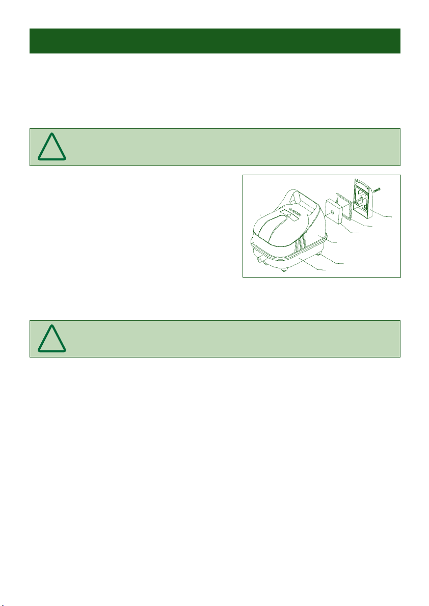
Connect the outlet pipe supplied and the metal valve air divider using the clips to secure.
Insert one end of each piece of air line required into the outlet nozzles of the air divider.
Place air stones onto the other end of the air line. These should then be placed into the pond
and /or filter.
Ensure that all the outlet valves are in the fully open position before the air pump is started.
Switch on the air pump. If the overall air output is to high it is recommended that one of the
air stones and air lines is removed and the remaining valves opened to reduce the air output
to the remaining air stones.
Adjustments to individual air stones can now be made. Shut off the individual valves in
small increments until the desired output is achieved.
The air stones should be positioned to provide maximum aeration and circulation in the
pond. (Note: For use in winter, air stones should be placed no lower than 30cm from the
bottom of the pond, to ensure the warmer, lower water regions remain undisturbed).
!
Koi Air Instruction Leaflet 2.qxd 30/3/06 13:51 Page 9
!
8. MAINTENANCE
Changing Replaceable Parts
Koi Air pumps have been designed to run reliably for many years if correctly maintained. Koi
Air pumps, in common with all air pumps, contain perishable rubber parts that have a
limited life span. These parts have been designed so they can be easily replaced therefore
maintaining the excellent pumping performance.
IMPORTANT: As a rule all perishable rubber parts should be replaced annually.
This will ensure that the Koi Air is giving the optimum pumping performance.
Tools Needed
Medium sized Phillips head screwdriver.
A pair of Pliers.
Replacing the Air Intake Foams (See Diagram)
Step by step guide
1. Remove the screw from the air filter cover part 1.
2. Remove and replace the air filter seal and air
filter foam parts 2/3.
Repeat steps 1 and 2 in reverse order to reassemble.
If you wish to change the flapper valves, move to changing
the flapper valves section 9.
IMPORTANT: Before commencing any maintenance on your Koi Air pump,
ensure it is isolated from the mains electricity supply.
Replacing the Outlet Foams
Step by step guide for Koi Air 25 (See Diagram)
1. Remove the air filter cover part 1.
2. Remove the 4 screws from the air pump base part 7 and remove the lid. Check that the
cover lid seal part 5 remains in place.
3. Remove the six screws from the motor base plate part 23 and gently lift the whole motor
from the air pump base part 7.
4. The three outlet foams part 32 and the outlet seal 6 can now be removed and replaced.
Repeat steps 1 and 4 in reverse order to reassemble.
Replacing the Outlet Foams
Step by step guide for Koi Air 50 / 65 (See Diagram)
1. Remove the air filter cover part 1.
2. Remove the 4 screws from the air pump base part 7 and remove the lid. Check that the
cover lid seal part 5 remains in place.
3. Remove the six screws from the motor base plate part 25 and gently lift the whole motor
from the air pump base part 7.
4. The three foams part 34 and the outlet seal part 33 and 6 can now be removed and replaced.
Repeat steps 1 and 4 in reverse order to reassemble.
!
Replacing the Intake Foams
1
2
3
4
8
7
Koi Air Instruction Leaflet 2.qxd 30/3/06 13:51 Page 10