Hidrotermal Filtration Combo PC Series User manual

Filtration Combo Series
PC Series
USER MANUAL

1. Filter Parameters
Model Filter Model Pump Model Valve Connection 0.5-0.8mm
Sand Weight
Flow
Area
Design
Flow
HT-PC350-6w HT-PG350 Hidro-BPS050 1.5 50mm 25 0.10m24.5m3/h
HT-PC450-6w HT-PG350 Hidro-BPS050 1.5 50mm 34 0.13m26.5m3/h
HT-PC350-6w HT-PG350 Hidro-BPS050 1.5 50mm 150 0.16m28m3/h
HT-PC500-6w HT-PG350 Hidro-BPS075 1.5 50mm 80 0.23m211.5m3/h
HT-PC650-6w HT-PG350 Hidro-BPS100 1.5 50mm 160 0.32m216m3/h
2. Function
The filter uses special filter sand to remove dirt particles from pool water. The filter sand is loaded into
the filter tank and functions as the permanent dirt removing media.The pool water, which contains
suspended dirt particles, is pumped through the piping system and is automatically directed by the
patented filter control valve to the top of the filter tank. As the pool water is pumped through the filter
sand, dirt particles are trapped by the sand bed, and filtered out. The cleaned Pool water is returned
from the bottom of the filter tank, through the control valve and back to the pool through the piping
system. This entire sequence is continuous and automatic and provides for total recirculation of pool
water through the filter and piping system.
After a period of time the accumulated dirt in the filter causes a resistance to flow, and the flow
diminishes and the reading of pressure gauge rises.This means it is time to clean your filter. With the
control valve in the BACKWASH position, the water flow is automatically reversed through the filter so
that it is directed to the bottom of the tank, up through the sand, flushing the previously trapped dirt
and debris out the waste line. Once the filter is backwashed of dirt,the control valve is manually
positioned to Rinse,and then positioned to filter to resume normal operation.
Figure 1

3. Installation
Only simple tools (screwdriver and wrenches), plus pipe sealant for plastic adapters, are required to install and
service the filter.
1) The filter must be placed on level, very firm,ground. Position the filter so that the piping connections, control
valve and winter drain are convenient and accessible for operation, service and winterizing.
2) Assemble the Pump to the platform base. The adapters must now be installed to connect the pump/filter
system.
a. Apply Teflon pipe sealant tape or Permatex No. 2 sealant to straight adapter. Screw adapter into pump
discharge port. (Do not over tighten.)
b. Apply Teflon pipe sealant tape or Permatex No. 2 sealant to elbow adapter. Screw adapter securely into
opening in control valve marked Pump.(Do not over tighten.)
3) Loading sand media. Filter sand media is loaded through the top opening of the filter.
a. Loosen flange clamp and remove Filter Control Valve (if previously installed).
b. Cap internal pipe with sand shield to preventsand from entering it. Be sure pipe is securely in place in
bottom under drain hub.
c.We recommend filling tank approximately 1/2 way with water to provide a cushioning effect when the filter
sand is poured in. This helps protect the under drain laterals from excessive shock.(Be sure the winter drain
cap is securely in place on drain pipe)
d.Carefully pour in correct amount and grade of filter sand, as specified.(Be sure center pipe remains centered
in opening.)Sand surface should be leveled and should come to about the middle of the filter tank. Remove
sand shield from internal pipe.
4) Assemble Filter control Valve to filter tank.
a.Place valve flange clamp around neck of tank. Do not tighten. Wipe filter flange dean.
b.Insert Filter Control Valve (with valve/flange 0-ring in place) into the tank neck, taking care that the center
pipe slips into the hole in the bottom of the valve. Place clamp around valve flange and tank flange just enough
so that the valve may be rotated on tank for final positioning.
c.carefully screw pressure gauge, with pipe tape, into 1/4 trapped hole in valve body. Do not over tighten.
d.Place hose clamps on clear hose and fit hose over staight and elbow adapters and secure with clamps. If it
is difficult to fit hose over adapters, place hose in hot water for several minutes. Connect pump to control valve
opening marked PUMP according to instructions. After connections are made,tighten valve flange clamp with
screwdriver, tapping around clamp with screwdriver handle to help seat valve flange clamp.
To prevent breakage and damage to pump and control valve, use only pipes sealants
specifically formulated for plastics. Do not over tighten fittings or adapters.
5) Connect pool return line to control valve opening marked RETURN. Complete suction line and waste
plumbing connections.
6) Refer to Pump owners Guide for electrical connections.
7) Check all connections including winter drain cap for leaks.
Check to confirm all laterals are in the down position before loading with sand.

4.Filter's Start-Up
1.Make sure the correct amount of filter sand is in tank and that all connections have been correctly made and
are secured.
2.Push the down control valve handle and rotate to BACKWASH position.(To prevent any damage to control
valve seal, always push down the handle before turning.)
3.Start the pump according to the pump manual (Make sure all suction and return lines are opened), allowing the
filter tank to fill in with water.)
4. Turn pump off and set valve to RINSE position. Start pump and operate until water in sight glass is clear-
about to 1 minute. Tum pump off and set valve to FILTER position and restart pump. The filter is now operating
at the normal filtering mode, removing dirt particles from the pool water.
5. Adjust the pool suction and return valves to achieve desired flow. Check the system and the filter for water
leaks and tighten connections, bolts, nuts, as required.
6. Acknowledge the initial pressure gauge reading when the filter is clean. (It will vary from each pool depending
on the pump and general piping system.) As the filter removes dirt and impurities from the pool water, the
accumulation in the filter will cause the pressure to rise and flow to diminish. When the pressure gauge reading
is 8-10 PSI (0.55-0.69 BAR) higher than the initial "clean" pressure you noticed, it is time to backwash (clean)
the filter (see BACKWASH under Filter Control Valve Functions).
To prevent damage to the pump and filter and for proper operation of the system, clean pump strainer and
skimmer baskets regularly.
5. BACK WASHING
The function of backwashing is to separate the deposited particles from filter media grains and flush them from
the filter bed. Backwashing is achieved by reversing the flow of water through the filter bed at a fairly high flow
rate. This high flow rate expands the filter bed and the water collects the debris taking it to waste.
1. CONDITIONS FOR BACKWMHING
Time for backwashing is determined by the following conditions:
a. The flow rate through the filter bed decreases until it is insufficient to meet the demand.
b. The removal efficiency of the filter bed decreases to the point where the effluent quality deteriorates and is no
longer acceptable.
c. When the pressure gauge reading is 50 kPa (7.2 psi) higher than the start up pressure.
d. If the filter is connected to mains water, pressure rise is not an accurate indicator as mains pressure tends to
fluctuate. It is best to rely on the actual flow rate.
During initial clean-up of the pool water, it may be necessary to backwash frequently due to the
unusually heavy initial dirt load in the water.
To prevent unnecessary strain on piping system and valves, always shut off pump before
switching filter control valve positions.
All suction and discharge valves must be open before operating the filter system. Failure to do
so could cause severe personal injury and/or property damage. Once water flow is steady out
the waste line, run the pump for at least 2 minutes.An initial backwashing of the filter is
recommended to remove any impurities or fine sand particles in the sand media.
Recommends that you backwash a swimming pool sand filter in a residential installation at
least once a month.

2.IMPORTANCE OF BACKWMHING
The importance of backwashing cannot be overstated. Dense filter media can become "packed" without proper
and frequent enough backwashing. Debris will remain trapped and create channeling within the filter bed.
This will result in the filter bed exhausting early. Moreover, if debris is not flushed from the media grains.the filter
bed will become dirtier and dirtier as time goes on until the filter operation fails.
3. BACKWMHING INSTRUCTIONS
a. Switch off the Pump I Close the Inlet Valve.
b. Release the filter's pressure by loosening Pressure Release Valve until the Pressure Gauge needle drops to
zero <O>.
c. Retighten Pressure Release Valve.
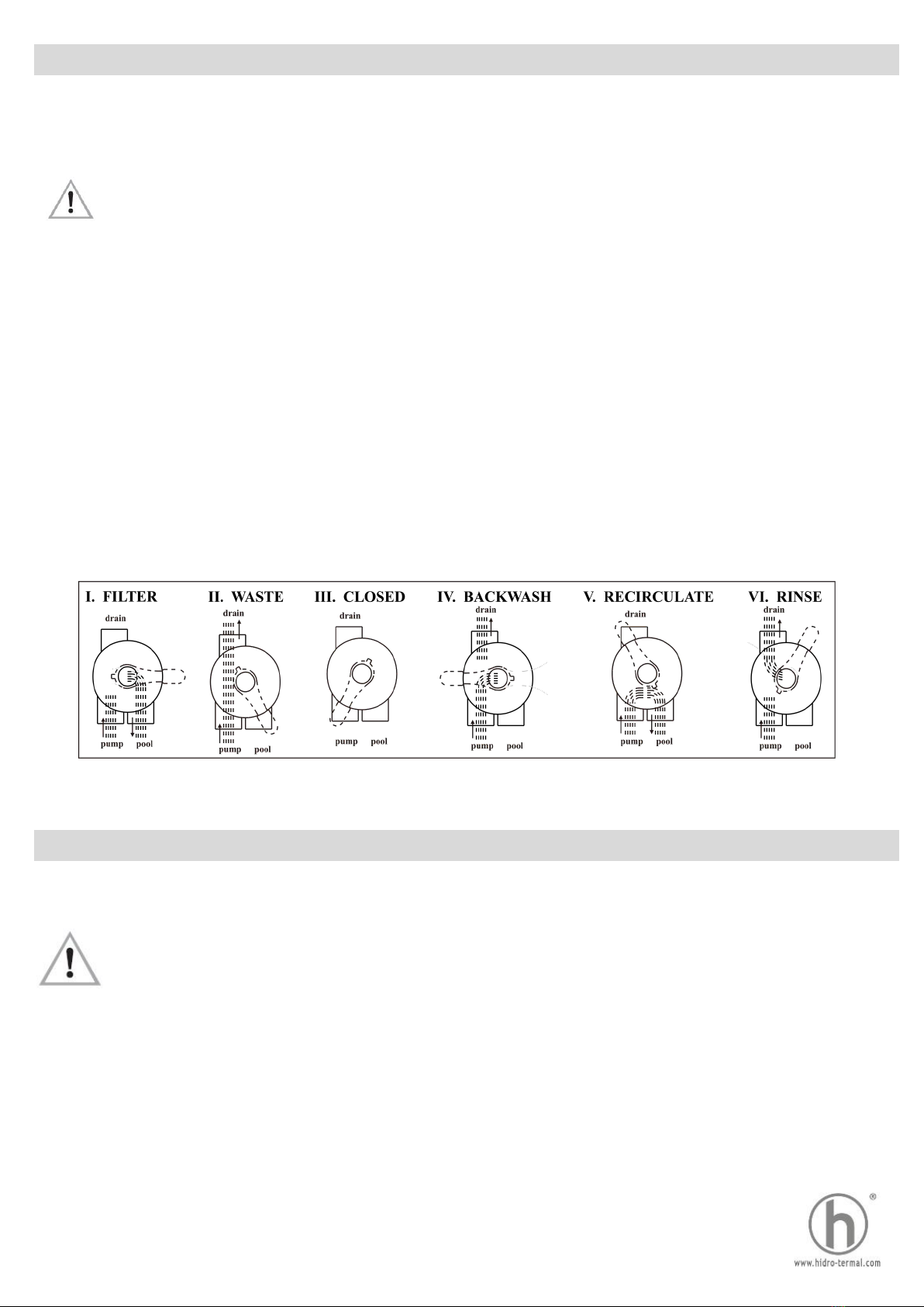
d. Depress and turn Handle 180"C to the BACKWASH position.
In the BACKWASH position.the water flow is automatically reversed through the filter so that it is directed to the
bottom of the filter vessel, up though the sand, flushing the previously trapped dirt and debris out the waste line.
e. Switch on the Pump I Open the Inlet Valve. Backwash water will flow out through drain pipe.
f. When the backwash water in the sight glass appears clear, Switch off the Pump I Close the Inlet Valve.
g. Depress and tum the handle to the RINSE position.
In the RINSE water flow is directed through the filter bed and out of the filter through the backwash outlet.
This process settles the filter media bed into place and ensures any dirt or debris is rinsed out of the
filter,preventing possible return to the pool.
h. Switch on the Pump I Open the Inlet Valve. Rinse water will flow out through the drain pipe.
i. When the rinse water in the sight glass appears clear. Switch off the Pump I Close the Inlet Valve.
j. Depress and tum the handle to the Filter position and Switch on the Pump I Open the Inlet Valve for normal
operation.
6. MAINTENANCE
The filter media will only require replacement once it has reached the limits of its designated life. Refer to the
product information of the particular filter media used.
To ensure the maximum life of the selected filter media, please follow the procedures below:
1. Backwash the filter regularly according to the instructions set under "Backwashing".
2. Refer to the specifications of the filter media used and implement regeneration procedures accordingly.
3. Maintain a correct chemical balance your pool / spa water. The chemical balance of water is a relationship
between its Ph, total alkalinity, calcium hardness and water temperature. The water must be maintained at all
times to the following:
PH LEVEL: BETWEEN 7.2 & 7.8.
TOTAL ALKALINITY: BETWEEN 80 & 150ppm. CALCIUM HARDNESS: BETWEEN 150 & 300ppm.
And within these tolerances be balanced to the Langelier Saturation Index within a range of -0.2 to +0.2.
4. Mains water and rural water supplies need to be monitored. Saturation (life) in mains water or bore (rural) will
vary depending on water quality.
5. To prevent damage to the pump and filter and for proper operation of the system, clean pump strainer and
skimmer baskets regularly.
6. Replace the pressure gauge if faulty readings are observed.
If a pump is installed, switch the pump on and off, instead of closing and opening the Inlet
Valve.
Testing kits are available to test the water yourself or alternately bring a sample of the water to
a professional pool and spa shop.

7. Filter Structure
1) Filter Replacement Parts
Key No. Product Description Qty
1 1.5" Top Mount Valve 1
2
Clip-L 1
Clip-R 1
Screw-clip 2
Nut-clip 2
3 O-ring 1
4
14" Tank 1
16" Tank 1
18" Tank 1
21" Tank 8
25" Tank 1
5 PVC pipe 1
6 Lateral Assembly 1
7 Lateral 8
8 Support pipe 1
9 Drain 1
10 Filter support stand 1
11 House 1
12 Pump 1
2) Pump Replacement Parts
Item Product Description Item Product Description Item Product Description
1Tie-in Nut 9Transparent cover 16 Impeller
2Tie-in 10 Gland cover of
Transparent cover
17 Mechanical seal
3O-Ring 18 Pump cover
4Drainge Plug 11 Open Cover Wrench 19 Pad
5O-Ring 12 O-Ring 20 Hexagon bolt
6Pump casing 13 O-Ring 21 O-Ring
7Filter 14 Difusser 22 Retaining block
8O-Ring 15 Activities Rings 23 Motor
Figure 2
Figure 3

8. TECHNICAL APPENDIX
1).INSTALLATION INSTRUCTIONS
The installation of the valve is carried out by screwingor sliping in, of the available connections according to the
installation scheme.
It is recommended to use adapter unions. Maintenance works and replacement are also
easier by using adapter unions.
2).FUNCTION AND INSTALLATION SCHEME
9.Warning
1. THIS FILTER OPERATES UNDER HIGH PRESSURE. WHEN ANY PART OF THE
CIRCULATING SYSTEM (e.g. CLAMP, PUMP, FILTER, VALVES, ETC.) IS SERVICED, AIR CAN
ENTER THE SYSTEM AND BECOME PRESSURIZED. PRESSURIZED AIR CAN CAUSE THE LID
OR VALVE TO BE BLOWN OFF WHICH CAN RESULT IN SEVERE INJURY, DEATH, OR
PROPERTY DAMAGE.DO NOT UNSCREW SCREWS OF FLANGE CLAMP WHILE FILTER
OPERATING.
2. TURN PUMP OFF BEFORE CHANGING VALVE POSITION.
3. TO PREVENT DAMAGE TO THE PUMP AND FOR PROPER OPERATION OF THE SYSTEM,
CLEAN PUMP STRAINER AND SKIMMER BASKET REGULARLY.
I. Filtration of Medium (i.e. Water)
Pool => Pump => Valve (to filter) =>
filter => Valve (from filter) => Pool
II. Drainage of Pool with Pump
Pool => Pump => Valve => Canal
V. Recirculation of Fluid Without
Filter (by pass filter)
Pool => Pump => Valve => Pool
IV. Cleaning of Filter Medium (i.e. Sand)
in upstream (reserved flow in filter)
Pool => Pump => Valve (from filter) =>
filter => Valve (to filter) => Waste
VI. Cleaning of Filter Medium (i.e. Sand)
after Backwash
Pool => Pump => Valve (to filter) => filter
=> Valve (from filter) => Waste
III. No Circulation
Do not operate pump.
Pool => Pump => Valve
Figure 4
NOTE
Table of contents
Other Hidrotermal Water Filtration System manuals
Popular Water Filtration System manuals by other brands

A.O. Smith
A.O. Smith aosbath MAX4 instruction manual

Jandy
Jandy AquaPure Installation and operation manual

JDS Uniphase
JDS Uniphase TB9 Series user manual

Econ
Econ 1096 Installation & operation manual

Polaris
Polaris PRESTIGE PAG19SF owner's manual

Pentair
Pentair EVERPURE PRO Installation and operating instructions

Judo
Judo i-soft TGA 2 Installation and operating instructions

3M
3M Aqua-Pure APIL3 Installation and operating instructions

Eaton
Eaton MAXILINE MBF Series operating manual

CARVIN
CARVIN Splash Pak Owner's manual and installation guide

AQUAMAXX
AQUAMAXX HOB-1.5 installation guide

3M
3M DP1XX instruction manual