manuals.online logo
Brands
  1. Home
  2. •
  3. Brands
  4. •
  5. Hidrotermal
  6. •
  7. Water Filtration System
  8. •
  9. Hidrotermal HT-BFV17 Manual

Hidrotermal HT-BFV17 Manual

INSTALLATION AND MAINTENANCE MANUAL
HT-BFV PE Sand Filter
1. Function
425 500 600 650
767 890 983 1028
75 75 75 90
526 650 743 787
390 390 390 560
579 702 795 839
635 758 850 895
Ф D(mm)
B(mm)
A(mm)
Ф P(mm)
N(mm)
The filter uses special filter sand to remove dirt particles from pool water. The filter sand is loaded
into the filter tank and functions as the permanent dirt removing media. When the control valve is in
the FILTER position, the pool water which contains suspended dirt particles, is pumped through the
piping system and is automatically directed by the patented filter control valve to the top of the filter
tank. As the pool water is pumped through the filter, dirt particles are trapped by the sand bed, and
filtered out. The cleaned Pool water is returned from the bottom of the filter tank, through the
control valve and back to the pool through the piping system. This entire sequence is continuous
and automatic and provides for total recirculation of pool water through the filter and piping system.
After a period of time the accumulated dirt in the filter causes a resistance to the flow, and make it
diminish. This means it is time to clean your filter. With the control valve in the BACKWASH
position, the water flow is automatically reversed through the filter so that it is directed to the
bottom of the tank, up through the sand, flushing the previously trapped dirt and debris out the
waste line. Once the filter is back-washed of dirt, set control valve to RINSE position and run pump
for about 1/2 to 1 minute, and then to resume normal filtering.
HT-BFV17
HT-BFV20
HT-BFV24
HT-BFV26
M(mm)
H(mm)
Please read and follow this MANUAL before installing and using the filter!
Maximum working pressure : 50psi.
Maximum water temperature : 50
。C
Stop the pump before changing valve position!
P1
3 Replacement parts of filter
ID Description QTY ID Description QTY
1Handle 1 12 Body-diffuser assy 1
2Screw-handle 1 13 Bulkhead assy 1
3Washer-B 1 14 Plug 1
4
Function point-out panel
115 Pressure gauge 1
5Lid assy 1 16 Sight glass 1
6Washer-plastic 1 17 Sight glass O-ring 1
7Washer-S 1 18 Rotor 1
8Spring 119 Orer drain,diffuser 1
9Rotor 1 20 O-ring,filter 1
10 Gasket 1 21 Plastic clamp 1
11 O-ring lid 1 22 Screw-clip 1
P2
ID Description QTY ID Description QTY
1 Multiport valve1.5'' 1 5 Center pipe 1
Plastic clamp 1 6 Lateral assembly 1
Or Clip-Stainless Steel 1 7 Lateral 8
Lock nut 1 8 Support pipe 1
3 Gasket of flange 1 9 Drain 1
Tank 17" 1 10 Filter support stand 1
Tank 20" 1
Tank 24" 1
Tank 26" 1
2
4
P3
4 Installation
5 Install/Start up of filter
Only simple tools (screwdriver and wrenches), plus pipe sealant for plastic adapters, are required to install
and service the filter.
1.The filter should be placed on a reasonably level surface and provide adequate drainage.
Position the filter so that the piping connections, control valve are convenient and accessible for operation and
service ,The filter should be placed as close to the pool as possible to reduce line loss from pipe friction.
2.Loading the sand media. Filter sand media is loaded through the top opening of the filter.
a.Loosen flange clamp and remove filter control valve (if previously installed).
b.Cap internal pipe with plastic cap to prevent sand from entering it.
c.We recommend filling tank approximately half full of water to provide a cushion effect when the filter sand is
poured in. This helpsprotect the under-drain laterals from excessive shock.
d.Carefully pour in correct amount and grade of filter sand. (Be sure center pipe remains centered in
opening.) Sand surface should be leveled and up to about the middle of the filter tank. Remove plastic cap
from internal pipe.
3.Assemble filter control valve to filter tank.
a.Insert filter control valve (with O'ring in place) into the tank neck, beware that the center pipe slips into the
hole in the bottom of the valve.
b.Place two plastic clamps around valve flange and tank flange and tighten just enough so that the valve may
be rotated on tank for final positioning.
c.Carefully screw pressure gauge (with O'ring in place) into tapped hole in valve body. Do not over-tighten.
d. Connect pump to control valve opening marked PUMP. After connections are made, tighten valve flange
clamps with screwdriver,tap around clamp with screwdriver handle to help seat valve flange clamp.
4.Make return to pool pipe connection to control valve opening marked RETURN and complete other
necessary plumbing connections, suction lines to pump, waste, etc.
5.Make electrical connections to pump following pump instructions.
6.To prevent water leakage, be sure all pipe connections are tight.
1. Be sure correct amount of filter sand is in tank and that all connections have been made and secured.
2. Push down control valve handle and rotate to BACKWASH position. (To prevent damage to control valve
seal, always push down handle before turning.)
3. Start pump according to pump instructions (be sure all suction and return lines are open),allowing the filter
tank to fill with water .Once water is flowing out of the remove any impurities or fine sand particles in the sand
media.
4. Stop the pump and set valve to RINSE position. Start pump and operate until water in sight glass is clear,
about 1/2 to 1 minute. Stop the pump and set valve to FILTER position and then restart pump. The filter is
now operating in the normal filter mode, filtering dirt particles from the pool water.
5. Adjust pool suction and return valves to achieve desired flow. Check system and filter for water leaks and
tighten connections,bolts, nuts, as required.
6. Note the initial pressure gauge reading when the filter is clean. (It will vary from each pool depending upon
the pump and general piping system.) As the filter removes dirt and impurities from the pool water, the
accumulation in the filter will cause the pressure to rise and flow to diminish. When the pressure gauge
reading is 150KPa/1.5Kg/cm,higher than the initial "clean" pressure you noted,it is time to backwash the filter
(see BACKWASH under filter and control valve functions).
During initial clean-up of the pool water it may be necessary to backwash frequently
d
ue to the unusually heavy initial dirt load in the water.
P4
6 Technical data
7 Warning
1. Installation instruction
The installation of the valve is carried out by screwing or sliping in, of the available connections according to
the installation scheme.
I. Filtration of medium (i.e.
water)
→filter → valve (from filter) →
pool
Pool → pump → valve (to filter)
III. No circulation
Do not operate pump.
Pool → pump → valve
V. Recirculation of fluid without
filter (by pass filter)
Pool → pump → valve → pool
2. Function and installation scheme
II. Drainage of pool wtih pump
Pool → pump → valve → canal
IV.Cleaning of filter medium (i.e.sand)
in upstream (reserved flow in filter)
Pool → pump → valve (from filter) →
filter → valve (to filter) → waste
VI.Cleaning
(i.e. sand) after backwash
Pool → pump → valve (to filter) →
filter → valve (from filter) → waste
1.This filter operates under high pressure. When any part of the circulating system (e.g., clamp, pump, filter, valves, etc.)
is serviced, air can enter the system and become pressurized. Pressurized air can cause the lid or valve to be blown off
which can result in severe injury, death, or property damage. Do not unscrew screws of flange clamp while filter operating.
2.Turn pump off before changing valve position.
3.To prevent damage to the pump and for proper operation of the system, Clean pump strainer
and skimmer baskets regularly.
It is recommended to use adapter unions.Maintenance works and replacement are
also easier by using adapter unions.
P5

This manual suits for next models

3

Other Hidrotermal Water Filtration System manuals

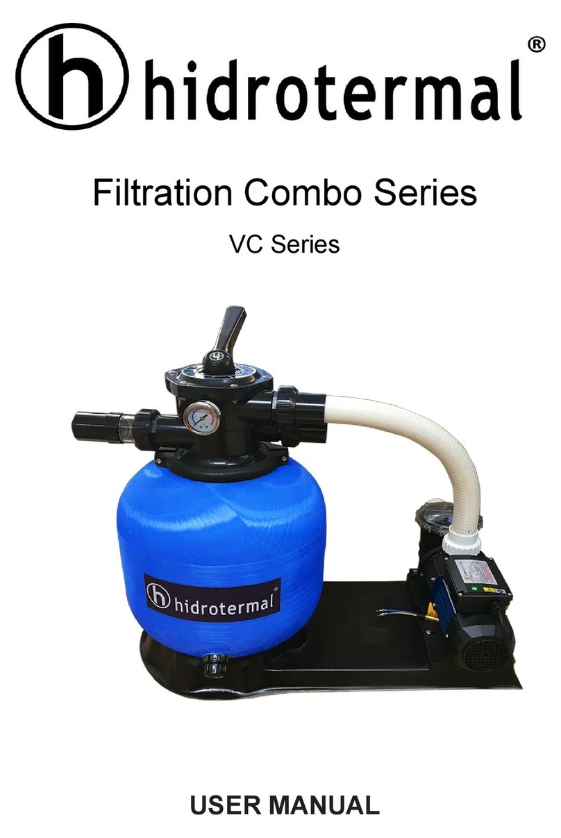
Hidrotermal Filtration Combo Series User manual

Hidrotermal

Hidrotermal Filtration Combo Series User manual

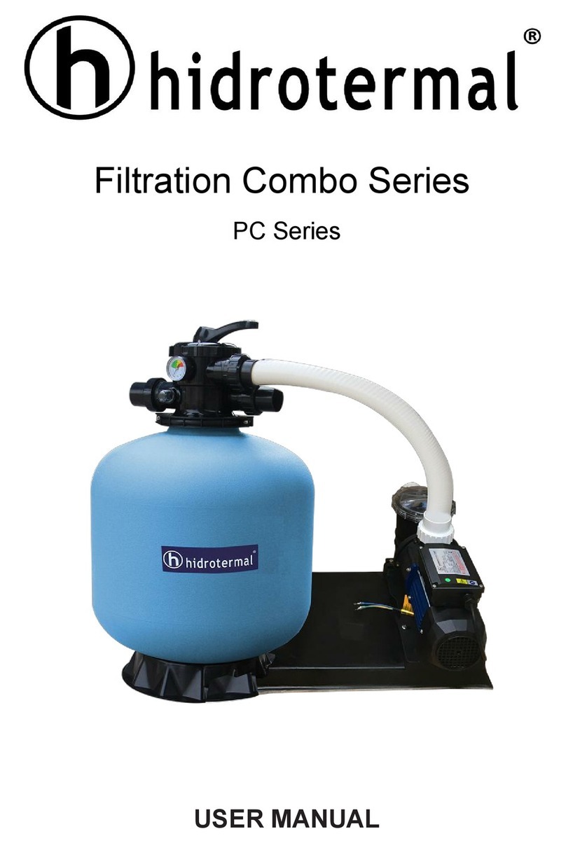
Hidrotermal Filtration Combo PC Series User manual

Hidrotermal

Hidrotermal Filtration Combo PC Series User manual

Popular Water Filtration System manuals by other brands

Berkey Go Berkey Kit manual

Berkey

Berkey Go Berkey Kit manual

GE RPWF use and care manual

GE

GE RPWF use and care manual

ACO Lipumax-P installation guide

ACO

ACO Lipumax-P installation guide

Bestway 58497 owner's manual

Bestway

Bestway 58497 owner's manual

CRS 202910 Operation guide

CRS

CRS 202910 Operation guide

Pentair FLECK 5800 SXT Service manual

Pentair

Pentair FLECK 5800 SXT Service manual

Propur ProMax PMC-4000 instructions

Propur

Propur ProMax PMC-4000 instructions

Dometic RO400 User instructions

Dometic

Dometic RO400 User instructions

STIEBEL ELTRON FOUNTAIN 7S user manual

STIEBEL ELTRON

STIEBEL ELTRON FOUNTAIN 7S user manual

Astral Pool Combo 27413 Instruction and operation manual

Astral Pool

Astral Pool Combo 27413 Instruction and operation manual

Waterco HYDROCHLOR ST owner's manual

Waterco

Waterco HYDROCHLOR ST owner's manual

WaterTech PURE PRO QC Installation, operation and service manual

WaterTech

WaterTech PURE PRO QC Installation, operation and service manual

amiad SAF X Series Installation, operation & maintenance instructions

amiad

amiad SAF X Series Installation, operation & maintenance instructions

Aqua PRO AP-600W-A5-GST2 manual

Aqua PRO

Aqua PRO AP-600W-A5-GST2 manual

Whirlpool WHER25 Performance data sheet

Whirlpool

Whirlpool WHER25 Performance data sheet

MP Aquinity2 P10 user manual

MP

MP Aquinity2 P10 user manual

Acuva Arrow Series Owner's Product Manual

Acuva

Acuva Arrow Series Owner's Product Manual

EcoQuest Living Water IIs CT owner's manual

EcoQuest

EcoQuest Living Water IIs CT owner's manual

manuals.online logo
manuals.online logoBrands
  • About & Mission
  • Contact us
  • Privacy Policy
  • Terms and Conditions

Copyright 2025 Manuals.Online. All Rights Reserved.