Hidrotermal Filtration Combo Series User manual

Filtration Combo Series
VC Series
USER MANUAL

1. Fiberglass Filter Parameters
Model Filter Model Pump Model Valve Connectio 0.5-0.8mm
Sand Weight Flow Rate
HT-VC400-6W HT-V400 Hidro-BPS050 1.5 50mm 35Kg 8m3/h
HT-VC450-6W HT-V450 Hidro-BPS050 1.5 50mm 45Kg 10m3/h
HT-VC525-6W HT-V525 Hidro-BPS075 1.5 50mm 85Kg 12m3/h
HT-VC625-6W HT-V625 Hidro-BPS100 1.5 50mm 150Kg 16m3/h
2. Installation
Install filtration system including pump,filer tank and multiport valve.
The filter system should be installed as close as possible to the swimming pool and preferably at a leve of
0.50 metres below the surface of the water in the swimming pool. Make sure there is drainage available at the
place where the filter is to be installed.
PUMP
1.Only qualified, licensed personnel should install pump and wiring.
2.Electrical Contractors Please Note: All 220 volt 50 HZ pump must be wired to the main power supply trough
an approved and correctly rated contractor.
3.Allow for gate valve in suction piping.
4.Pump suction and discharge connections have moulder in thread stops, do not try to screw pipe in beyond
these stops.
FILTER TANK AND MULTIPORT VALVE
1.Loading the sand media.Filter sand media is loaded through the top opening of the filter.
a.Lossen the plastic clamps from tank neck.
b.Cap internal pipe with plastic cap to prevent sand from entering it.
c.We recommend filling tank approximately 1/2 way with water to provide a cushion effect when the filter
sand is poured in. This helps protect the under-drain laterals from excessive shock.
d.Carefully pour in correct amount and grade of filter sand. Be sure center pipe remains centered in
opening.Sand surface should be leveled and should come to about the middle of the filter tank. Remove
plastic cap from internal pipe.
2.Assemble filter control valve to filter tank.
a.Insert filter control valve(with O-ring in place)into the tank neck,taking care that the center pipe slips into the
hole in the bottom of the valve.
b.Place two plastic clamps around valve flange and tank neck and tighten just enough so that the valve may
Be rotated on tank for final positioning.
c.Carefully screw pressure gauge(with O-ring in place)into tapped hole in valve body.Do not over-
tighten.Connect pump to control valve opening marked PUMP with hose.After connections are made,tighten
clamps with screwdrive,tapping around clamp with screwdrive handle to help seat valve flange clamp.
3.Make return to pool pipe connection to control valve opening marked RETURN and complete other
necessary plumbing connections,suction lines to pump,waste,etc.
4.To prevent water leakage,be sure all pipe connections are tight.
Figure 1

3. Filter's Start-Up
1.Make sure the correct amount of filter sand is in tank and that all connections have been correctly
made and are secured.
2.Push the down control valve handle and rotate to BACKWASH position. (To prevent damage to
the control valve seal, always push down the handle before turning.)
3.Start the pump according to the pump manual.Never tun pump dry !Running pump dry may
damage seals, causing leakage and flooding !(Make sure all the suction and return lines are
opened), allowing the filter tank to fill in with water. Once the water is flowing out it removes any
fine sand particles and impurities from the sand media.
4.Stop the pump and set valve to the RINSE position. Start the pump and operate for 1 minute until
water is clear. Stop the pump and set the valve to the FILTER position and then restart the pump.
The filter is now operating at the normal filtering mode, removing dirt particles from the pool water.
5) Adjust the pool suction and the return valves to achieve desired flow. Check the system and the
filter for water leaks and tighten the connections, bolts, nuts, as required.
6.Acknowledge the initial pressure gauge reading when the filter is clean. (It will vary from each
pool depending on the pump and general piping system.) As the filter removes dirt and impurities
from the pool water , the accumulation in the filter will cause the pressure to rise and flow to
diminish. When the pressure gauge reading is 1.5 BAR higher than the initial "clean" pressure you
noticed, then it is time to backwash the filter (see BACKWASH under filter and control valve
functions).
NOTE: During initial clean-up of the pool water it may be necessary to backwash
frequently due to the unusually heavy initial dirt load in the water.
4. Fiberglass Filter Structure
1) Filter Replacement Parts
Item Product Description
1 1.5" Top Mount Valve
2 1.5" Union with Sight Glass, O-ring
3Oil Pressure Gauge with O-ring(40Psi)
Connector for Pressure Gauge
4 1.5" Union set with O-ring
5 Plastic Hose with Nut
6 O-ring for Pump
7 Pump
8 Pump Assembly Screw
9 Fastener for Filter Base
10 Water Drain Set
11 Combo Base
12 Laterals (126mm)
13 Lateral Assembly with center Pipe
14 Filter Tank
15 O-ring for Filter Neck
16 M6*50 Screw With Nut
Clamp Lock
Figure 2

2) Pump Replacement Parts
Item Product Description Item Product Description
1 Tie-in Nut 13 O-Ring
2 Tie-in 14 Difusser
3 O-Ring 15 Activities Rings
4 Drainge Plug 16 Impeller
5 O-Ring 17 Mechanical seal
6 Pump casing 18 Pump cover
7 Filter 19 Pad
8 O-Ring 20 Hexagon bolt
9 Transparent cover 21 O-Ring
10 Gland cover of Transparent cover 22 Retaining block
11 Open Cover Wrench 23 Motor
12 O-Ring
Release allairfrom filter and piping system.
In a flooded suction system (water source higher than pump), pump will prime itself when suction and
discharge valves are opened.
If pump is not in a flooded suction system, unscrew and remove trap cover; fill trap and pump with
water.
Clean and inspect Ring; re-install on trap cover.
Replace trap cover on trap; tum clockwise to tighten cover.
NOTICE: Tighten trap cover by hand only. Pump should prime now. Priming time will depend on
vertical length of suction lift and horizontal length of suction piping.
Figure 3

3) Multiport Valve Replacement Parts
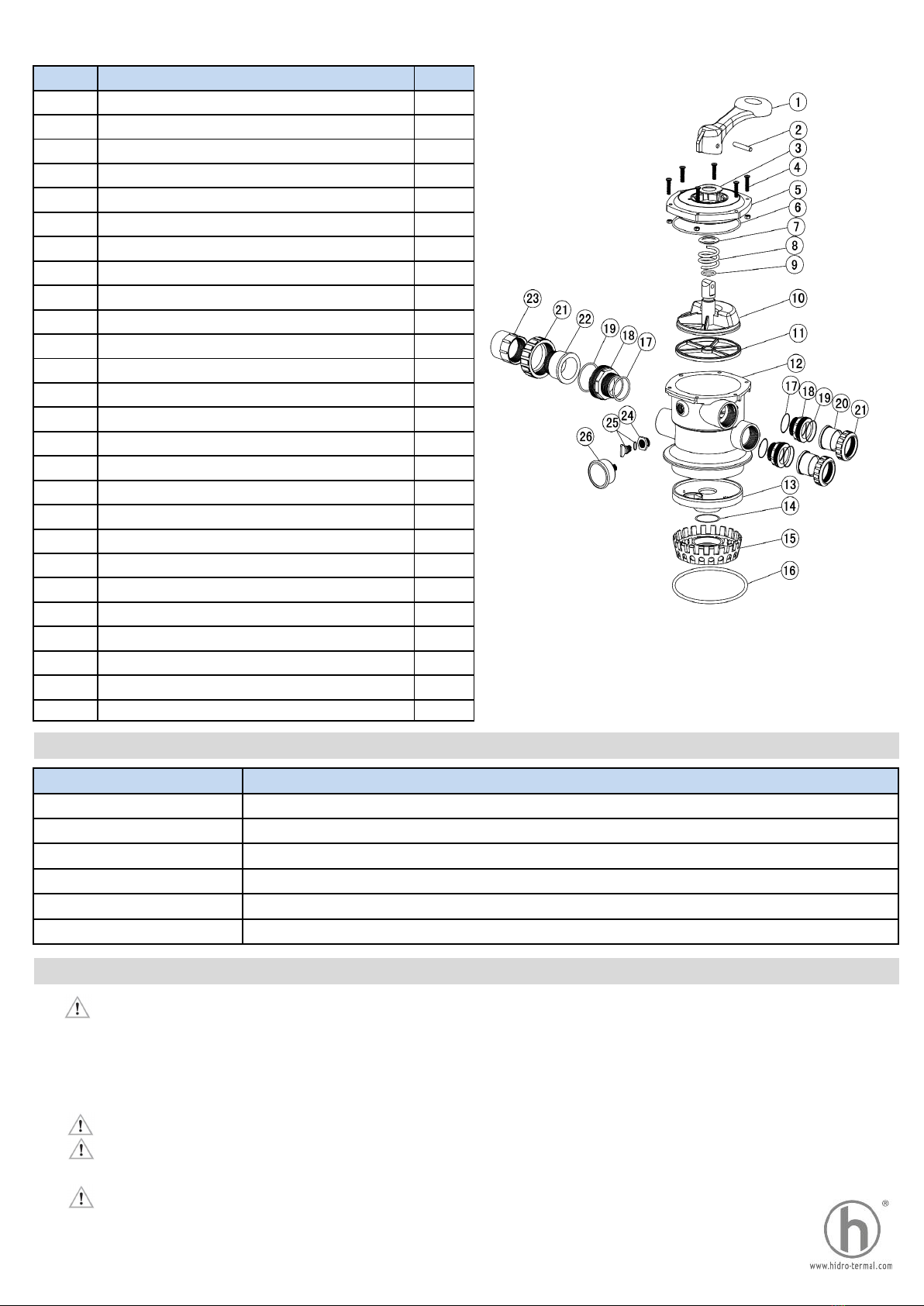
Item Product Description Qty
1 Handle (Big) 1
2 Pin for Handle 1
3 Washer for Handle 1
4 M6*30 Screw with Nut for Standard Lid 6
5 1.5" Top Mount Valve Standard Lid (Black) 1
6 O-ring for 1.5" Valve Lid 1
7 Washer for Spring 1
8 Spring for 1.5" Top Mount Valve 1
9 O-ring for 1.5" Valve Rotor 2
10 1.5" Valve Rotor 1
11 Spider Gasket 1
12 1.5" Top Mount Valve Bottom Body Clamp (black) 1
13 1.5" Diffuser 1
14 O-ring for Diffuser 1
15 1.5" Top Mount Valve Over Drain Diffuser 1
16 O-ring 1
17 O-ring for 1.5" Connector 3
18 1.5" Connector (Black) 3
19 O-ring for 1.5" Union 3
20 1.5" Union (A/E) 2
21 1.5" Union Nut (black) 3
22 1.5" Union with sight glass (short) 1
23 1.5" Union with sight glass holder 1
24 Connector for pressure gauge/stopper 1
25 Drain Plug with O-ring 1
26 Pressure Gauge with O-ring (40psi) 1
5. Valve Positions Function
Valve Position Function
FILTER Normal Filtration and Vacuum
BACK WASH Clean Filter by reversing the flow
RINSE Use after backwash to flush dirt from valve
WASTE By-passes filter, use to vacuum the waster for lowering water level
RECIRCULATE By-passes filter for circulating water to pool
CLOSED Shut off all flow to filter or pool
6.Warning
1. THIS FILTER OPERATES UNDER HIGH PRESSURE. WHEN ANY PART OF THE
CIRCULATING SYSTEM (e.g. CLAMP, PUMP, FILTER, VALVES, ETC.) IS SERVICED, AIR
CAN ENTER THE SYSTEM AND BECOME PRESSURIZED. PRESSURIZED AIR CAN CAUSE
THE LID OR VALVE TO BE BLOWN OFF WHICH CAN RESULT IN SEVERE INJURY,
DEATH, OR PROPERTY DAMAGE.
2. TURN PUMP OFF BEFORE CHANGING VALVE POSITION.
3. TO PREVENT DAMAGE TO THE PUMP AND FOR PROPER OPERATION OF THE
SYSTEM, CLEAN PUMP STRAINER AND SKIMMER BASKET REGULARLY.
4. DO NOT UNSCREW SCREWS OF FLANGE CLAMP WHILE PUMP IS RUNNING.
Figure 4
This manual suits for next models
5
Table of contents
Other Hidrotermal Water Filtration System manuals
Popular Water Filtration System manuals by other brands

SmartPool
SmartPool Smart Clear EQ-SC-1900 Installation instructions and operation manual

JDS Uniphase
JDS Uniphase TB9 Series user manual

FILTRINOV
FILTRINOV GS14 Installation and operating instructions

Donaldson
Donaldson BOFA FireBOX GA user manual

VGE
VGE FLEX UV-C manual

Purofilter
Purofilter 53-WF-02PF installation instructions