High Lifter PGL-KIT-RZRT User manual

PGL-KIT-RZRT 1

PGL-KIT-RZRT 2
IMPORTANT PRODUCT USE AND SAFETY INFORMATION / WARNINGS
This product is designed for use on ATVs and/or RUVs to lower the final drive gear ratio and increase ground
clearance. Purchasers should be aware that use of this product may increase the frequency of required
maintenance, part wear, and will raise the center of gravity on your ATV and/or RUV, increasing risk of roll-over,
injury and death on all types of terrain. It is your responsibility to always inform other operators and
passengers of this vehicle about the added risks with this product.
High Lifter’s products are designed to best fit user’s ATV/RUV under stock conditions. Adding, modifying, or
fabricating any OEM or aftermarket parts will void warranty. High Lifter Products, products could interfere with
other aftermarket accessories. If the user has aftermarket products on machine, contact High Lifter Products to
verify that they will work together. Adding aftermarket suspension components and/or more aggressive tires
can cause breakage of other OEM driveline components such as differentials, axles or drive shafts.
Riders should be advised that the handling characteristics of a taller ATV and/or RUV are different and require
extra care when riding, particularly on the side of hills or off-camber situations. If you further raise the center
of gravity by adding taller tires, heavy loads to racks or seats, or by any other means, the ATV and/or RUV must
be operated with even more care, at slower speeds and on relatively flat ground. All turns should be done at a
slow speed, even on level ground.
Operation of an ATV and/or RUV with or without modified suspension components, while or shortly after
consuming alcohol or drugs, subjects the rider and passengers to the risk of serious bodily harm or possible
death. This risk is compounded if the riders do not wear an approved helmets and other safety gear. High Lifter
urges that all approved safety gear be worn when riding an ATV and/or RUV as a driver or passenger.
By purchasing and installing High Lifter Products, products, user agrees that should damages occur, High Lifter
Products will not be held responsible for loss of time, use, labor fees, replacement parts, or freight charges.
High Lifter Products will not be held responsible for any direct, indirect, incidental, special, or consequential
damages that result from any product purchased from High Lifter Products. The total liability of seller to user
for all damages, losses, and causes of action, shall not exceed the total purchase price paid for the product that
gives rise to the claim.
Dealers and other Installers
You are responsible for informing your customer and end user of the information contained above and the
increased potential hazards of operating an ATV and/or RUV equipped with modified suspension components.
If you install any suspension modifying components, it is your responsibility to also install the warning label
prominently in view of the driver and in prominent view of the driver and passenger on RUVs and multi-
passenger ATVs. They should also be instructed to notify anyone operating the vehicle, as well as any
passengers, that said vehicle is modified.
As discussed above, it is critically important that they be instructed in the need for slower speed operation,
regardless of terrain, after this lift kit is installed.

PGL-KIT-RZRT 3
The product is/will:
• Designed and intended for use on a UTV at slow speeds.
• Increase the center of gravity.
• Increase the turning radius.
• Increase the stopping distance when adding larger tires.
• Increase and accelerate wear of factory components including bushings, bearings, ball joints, and tie rod ends.
• We cannot guarantee fitment with other aftermarket accessories.
Safety Guidelines:
• Inspect all moving factory suspension components particularly ball joints, tie rod ends, control arm
connections, and brakes prior to each ride and replace if worn.
• Inspect clearances with control arms and brake lines prior to each ride.
• Wheel spacers should not be used with a Portal Gear Kit.
• 14” or larger wheels must be used with the Portal Gear Kit. 12” wheels cannot be used.
• Jumping, high speeds, and quick maneuvering should be avoided.
Maintenance Information:
• Check gear oil in portal boxes following 25 hours of riding or sooner, depending on how you ride.
• Use 4 oz of SAE 80W-90 Gear Lubricant as needed in each portal box.
• Replace worn factory components including bushings, bearings, ball joints, brakes, and tie rod ends when they
show wear.
Any vehicle equipped with a Portal Gear Kit must have the enclosed large format “Warning to Driver” decal
installed on the inside of the windshield or on the vehicle’s dash, within driver’s view. The “Warning to Driver”
decal is to act as a constant safety reminder for whoever may be operating the vehicle.
INSTALLING dealer: It is your responsibility to install the “Warning to Driver” decal and forward these
installation instructions to the vehicle owner for review of warnings, product use, and maintenance
information. Replacement Warning Decals are available FREE on request. These instructions are to be kept with
the vehicle registration papers and owner’s manual for the service life of the vehicle.
REFUSED Shipments/Order CANCELLATION:
Refused shipments are subject to a 20% restocking fee plus all associated freight costs. It is our goal to ship all
orders in a timely manner. If a customer wishes to cancel an order (provided it is not a special order product), it
is the responsibility of the customer to cancel the order prior to the product being shipped. If a customer
cancels an order after product has been shipped, refused shipment, cancellation, or return will be subject to a
20% restocking fee and any freight charges incurred. For orders outside the United States, any fees associated
with customs or duties are non-refundable.
DAMAGED Shipments:
All claims for damaged shipments must be made within 72 hours of delivery to the point of destination. Any
damage to package should be noted with carrier at the time of delivery if possible. We will not be responsible
for damage claims made over 72 hours after delivery to the point of destination.

PGL-KIT-RZRT 4
INTRODUCTION
• Read these instructions carefully. It is recommended that a professional mechanic perform the installation.
Care should be taken to follow all standard safety procedures.
• PRIOR to installation, a thorough inspection of the suspension should be made. Inspect the vehicles steering,
driveline, and brake systems, paying close attention to the suspension link arms and bushings, anti-sway bars
and bushings, tie rod ends, ball joints and wheel bearings.
• Also check the steering sector-to-frame and all suspension-to-frame attaching points for stress cracks. The
overall vehicle must be in excellent working condition. Any worn, bent or broken parts should be repaired
and/or replaced.
NOTE: Do not add or fabricate any components to gain additional suspension height.
NOTE: AFTER installation, another inspection should be made, checking for loose components or missing
hardware. Inspect, again after eight (8) hours of operation. Remember, your lug nuts.
NOTE: A factory service manual should be on hand for reference. The manual will contain fastener torque
specs, assembly techniques, and special tool requirements that are unique to this particular year and model
vehicle.
TORQUE SPECIFICATIONS - Check all brackets & bolts to be sure everything is tight
Box cap screws
8 ft lbs
Brake caliper bleeder screw
4 ft lbs
Brake line banjo bolt (caliper attachment)
50 ft lbs
Brake line banjo bolt (master cylinder attachment)
50 ft lbs
Brake rotor bolts
45 ft lbs
Caliper mounting bracket upper hole & box center hole bolts
90 ft lbs
Front & rear axle nut with shoulder
180 ft lbs
Front ball joint pinch bolts
50 ft lbs
Front Box to backing plate bolts (Upper & Lower)
105 ft lbs
Front & rear caliper mounting bolts
50 ft lbs
Front pinch bolt mounting bracket bolts
70 ft lbs
Lug nuts (cast rims)
90 ft lbs
Lug nuts (steel rims)
50 ft lbs
Oil drain & fill plugs
20 ft lbs
Radius bar bolt (Lower)
90 ft lbs
Radius bar bolt (Upper)
90 ft lbs
Rear Box to backing plate bolts (Lower)
105 ft lbs
Rear Box to backing plate bolts (Upper)
90 ft lbs
Spindle castle nut with washer
Min 120 ft lbs
Tie rod end to backing plate tie rod mount
90 ft lbs
Tie rod jam nut
15 ft lbs
Trailing arm to backing plate bolts (1/2")
90 ft lbs
Trailing arm to backing plate bolts (3/8")
40 ft lbs
Alignment, front toe tolerance 1/8” to 3/16” (3.2-4.8mm) Toe Out

PGL-KIT-RZRT 5
TOOLS REQUIRED
• Metric & standard socket assortments
• Metric & standard hex key/sockets
•Torque wrench
• Multi-purpose pliers
•Wire cutter/snips
• Mallet (Soft face hammer)
• Drift punch/pin
• Water-resistant grease
• DOT 4 brake fluid
• 80w90 gear oil
FRONT INSTALLATION
1. Prepare vehicle, front
2. Removal of front brake calipers & hubs
3. Front backing plate assembly & install
4. Front portal box assembly
5. Install front portal box
6. Install front drive shaft nut with shoulder & portal box lid cap
7. Assemble brake rotor and wheel hubs
8. Install front brake rotor assembly
9. Adjust front camber
10. Replace & route front brake lines
11. Install front brake calipers
12. Install front tires and wheels
REAR INSTALLATION
13. Prepare vehicle, rear
14. Removal of rear brake calipers &hubs
15. Rear portal backing plate install
16. Rear portal box assembly & install
17. Adjust rear camber
18. Install rear drive shaft jam nut, spindle spacer, & portal box lid cap
19. Install rear brake rotor assembly
20. Install rear brake hanger bracket & caliper
21. Install radius bars
FINAL INSTALLATION
22. Bleed brakes
23. Fill portal boxes with oil
24. Install rear tires & wheels
25. Front alignment
26. Install warning decals

PGL-KIT-RZRT 6
PARTS DIAGRAM
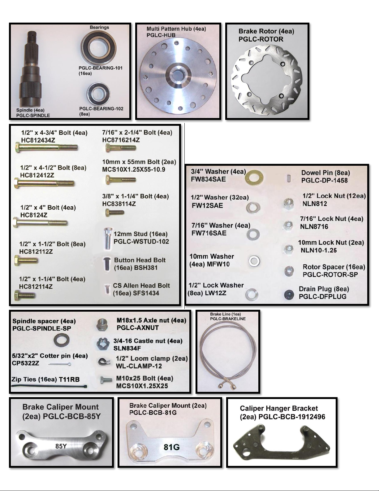
PGL-KIT-RZRT 7

PGL-KIT-RZRT 8
FRONT INSTALLATION
1. PREPARE VEHICLE
[THE FOLLOWING INSTRUCTIONS TAKE PLACE ON THE PASSENGER SIDE]
a. Begin by loosening the lug nuts on both front tires.
b. Raise the unit, using a suitable lifting device or procedure, until the front tires are off the ground.
c. If using a floor jack with stands, chock the rear wheels to prevent the unit from rolling. If using jack stands,
make sure the stands are placed under the frame and not the body.
d. Make sure the unit is stable and secure. Remove wheel nuts and front wheels.
2. REMOVAL OF FRONT BRAKE CALIPER AND HUB
a. Remove the upper & lower caliper mounting bolts (15mm).
b. Remove the front brake scraper from the caliper, it is no longer needed. (8mm)
c. It is not necessary to remove the brake line from the caliper at this time. Leave the brake hose attached to
the caliper and hang the calipers out of the way. Take precautions to ensure the brake hose isn’t stretched
or pinched.
d. Retain the factory bolts & nuts. They will be reused during the installation of the bolt-on portal boxes &
mounting brackets.

PGL-KIT-RZRT 9
e. Remove the cotter pin and loosen the front wheel hub castle nut. (27mm) Remove the nut and cone
washers, and then remove the hub.
f. Remove the front brake rotor assembly.
g. Disconnect the tie rod. (18mm)
h. Remove upper ball joint pinch bolt from the knuckle (15mm). Then remove the lower ball joint nut from the
knuckle. (18mm)
i. Remove the knuckle and retain the factory bolts & nuts. They will be re-used later in the install process.
PGL-KIT-RZRT 10
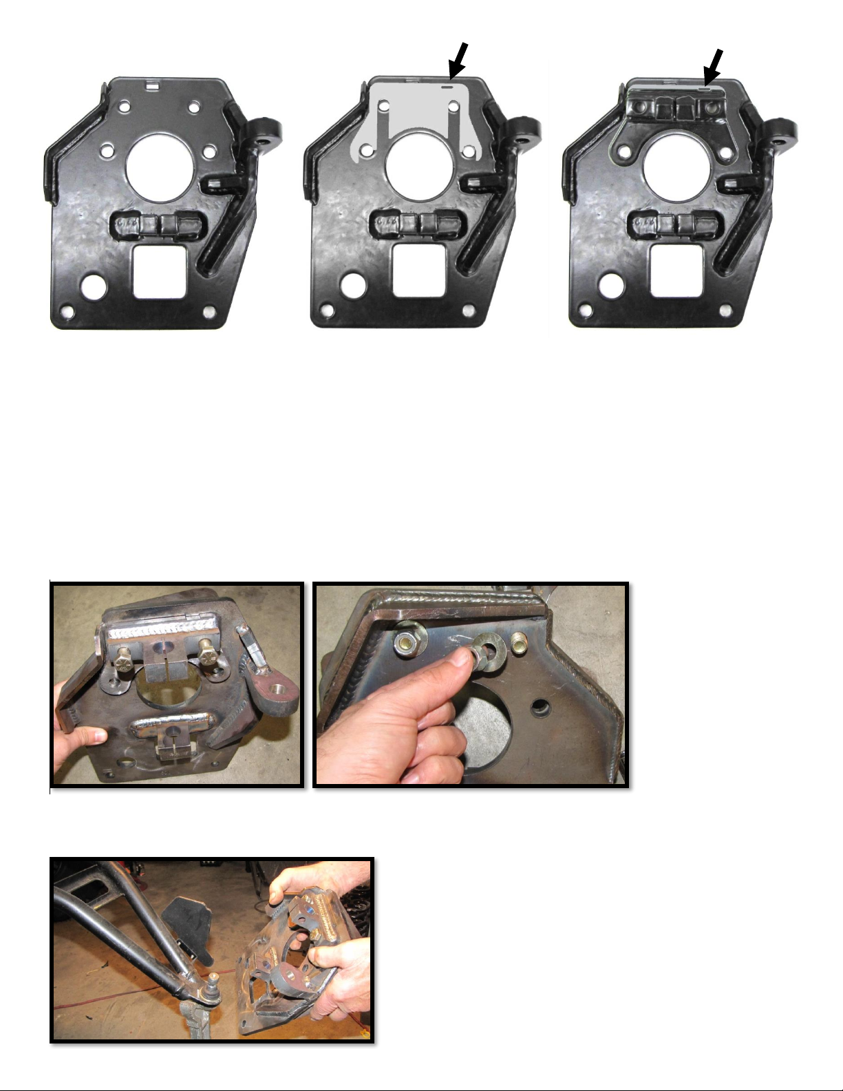
3. FRONT BACKING PLATE ASSEMBLY AND INSTALL
a. Find the front right backing plate (82A-R).
b. Place a 1/8” front shim (82o) to the upper backing plate and align it to the holes. This should set the
camber to ZERO once the assembled portal box is installed. The oval shape cut out should be to the top
right.
c. Find the front right upper ball joint mount bracket (82B-R). Place it on top of the shim and make sure all
the holes are aligned. The small cut out should be to the top right.
d. Insert 7/16 x 2-1/4” bolts through the upper mounting bracket and shim slots, and then out through the
front of backing plate. Slide (1) 7/16” washer onto each bolt and loosely fasten the bolts with 7/16” lock
nuts. (5/8)[70 ft lbs]
e. Properly position and insert the lower ball joint into the lower ball joint mounting bracket on the backing
plate assembly.
a
b
c
PGL-KIT-RZRT 11
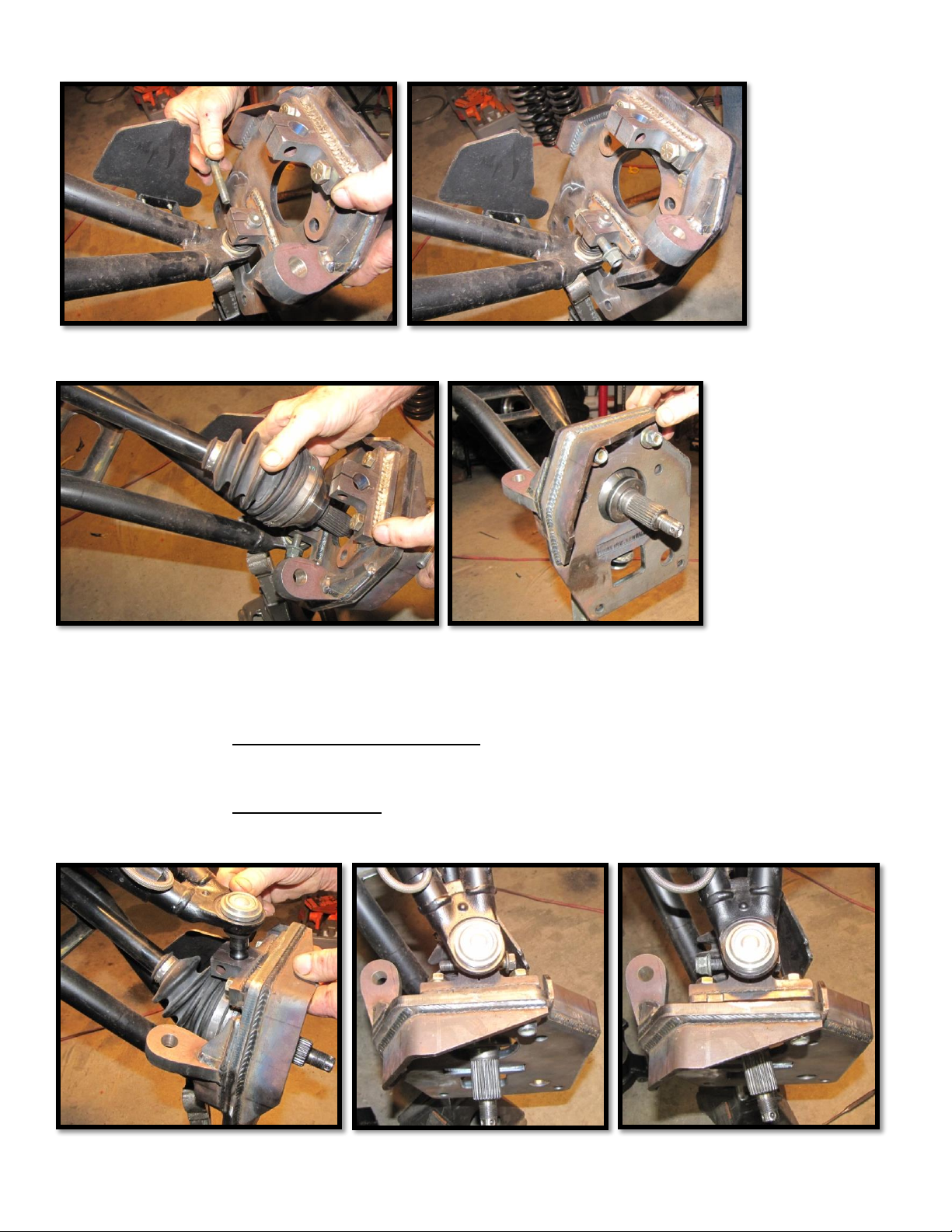
f. Secure with the factory bolt and nut. (18mm)[90 ft lbs]
Note: You may need to clean powder coating from the holes
g. Insert the axle into the backing plate.
h. Place the upper ball joint into the portal box assembly’s upper pinch bolt mount.
Note: You may need to clean powder coating from the holes.
-If you are using stock or non forward raked arms, then insert the factory bolt and fasten with the factory
nut. Torque front ball joint pinch bolt (15mm)[50 ft lbs]
-If you are using forward raked arms, then insert the supplied 10mm x 1.25 x 55mm bolt and fasten with
a 10mm x 1.25 lock nut. This bolt will provide more clearance. Torque front ball joint pinch bolt
(15mm)[50 ft lbs]
PGL-KIT-RZRT 12
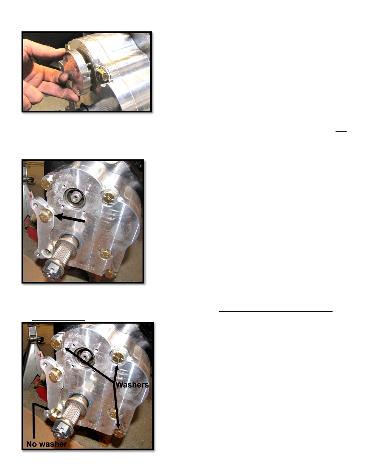
4. FRONT PORTAL BOX ASSEMBLY
a. Remove the (4) 8-32x1/2” screws & (1) cap and gasket from the lid of the portal box PGLC-BOX430-R-P.
b. The box comes pre-installed with a ½ x 1 ½” bolt and 1/2” lock washer in the upper caliper mount hole. You
will not re-use this lock washer for the front boxes. Just insert the ½ x 1 ½” bolt through the upper hole of
the caliper mounting bracket PGLC-BCB-85Y and place it in the corresponding fitted section of the front
portal box and fasten it tight. (3/4) [90 ft lbs]
c. Slide (1) 1/2” flat washer onto (3) ½ x 4 ½” bolts. Insert these bolts through the three holes shown below.
Then insert (1) ½ x 4 ½” bolt into the lower caliper mount hole. This bolt does not use a washer for the
front portal boxes.

PGL-KIT-RZRT 13
5. INSTALL FRONT PORTAL BOX
a. Apply waterproof grease to the drive splines. Make sure to apply product all around the outer edge as well.
b. Rotate the portal box assembly ‘Up & In’ as you guide the drive shaft axle through the inner drive gear.
c. Insert the bolts through the corresponding holes in the backing plate.
d. Loosely fasten the 4 ½” bolts with ½” flat washers and ½” lock nuts. Recheck all parts that were used and
make sure everything fits correctly, and then go ahead and tighten and torque all 4 ½” bolts. (3/4)[105 ft lbs]
e. Install the tie rod end in through the top of the portal box tie rod mount bracket. Fasten the tie rod end
with the factory nut. (18mm)[90 ft lbs]

PGL-KIT-RZRT 14
6. INSTALL FRONT DRIVE SHAFT NUT WITH SHOULDER & PORTAL BOX LID CAP
a. With the portal box assembly in place, double check that the factory axle shaft is properly aligned into the
drive gear of the portal box.
b. Apply LOCTITE 243 (Blue) to the supplied M18 axle nut with shoulder PGLC-AXNUT and tighten & torque
onto the drive shaft axle. (27mm)[180 ft lbs]
c. Align the portal box lid cap & gasket. Use the (4) 8-32x1/2” screws and install to the portal box. [8 ft lbs]
d. Slide the spindle spacer PGLC-SPINDLE-SP onto the spindle shaft.
PGL-KIT-RZRT 15
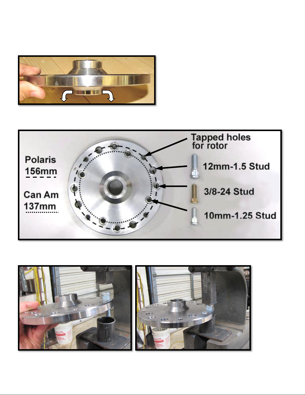
7. ASSEMBLE ALL BRAKE ROTORS & WHEEL HUBS
a. Locate all (4) PGLC-HUB multi pattern hubs so they can all be assembled at the same time. They are
designed to work with different bolt patterns.
b. One side of the hub has a shorter lip than the other. This side will face away from the UTV when installed.
Place this side face down on your working surface for the following steps.
c. With the shorter lip side faced down, find the bolt pattern that corresponds to your make and model with
the provided studs PGLC-WSTUD-102.
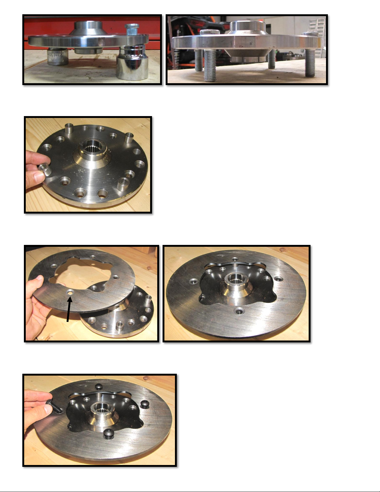
d. You can use a press to install the studs. You can also use large sockets as spacers to press them in. Take
care not to press the studs into the threaded tapped holes for the rotor!
PGL-KIT-RZRT 16
e. Once the studs are pressed in, locate and place (4) ½” brake rotor spacers (PGLC-ROTOR-SP) over the
tapped holes.
f. Locate a brake rotor PGLC-ROTOR. The side with the counter bores should be facing up. Place the rotor on
to the hub and line the holes up with the tapped holes.
g. Apply LOCTITE (RED) to (4) 3/8-16 x 1" button head bolts (BSH381). Insert the screws through the rotor,
the spacers, and then into the hub. Tighten and torque. [45 ft lbs]

PGL-KIT-RZRT 17
8. INSTALL FRONT BRAKE ROTOR ASSEMBLY
a. Apply waterproof grease to the spindle splines. Then slide the brake rotor assembly onto the spindle shaft.
a. Install the supplied 3/4 SAE grade 8 flat washer & tighten the 3/4-16 slotted castle nut. (1-1/16”-27mm)
[Minimum 120 ft lbs] Tighten the slotted nut further if needed to align grooves with holes in spindle for
cotter pin. Install the supplied large cotter pin. Both ends of the cotter pin must be folded.
9. ADJUST FRONT CAMBER
a. When checking the camber, it is necessary that the unit is leveled. You can do this by properly positioning
jack stands, bottle/floor jacks, and using a leveling tool. Be careful and make sure the unit is secure during
this process.
b. Now check the camber and determine if it is positive or negative. You want to set it as close as you can to
ZERO. To do this, you can visually look down the side of your UTV and use an angle locator tool. If it is
good, proceed to step #7. If not, then continue following these steps.

PGL-KIT-RZRT 18
c. If the camber is (-) you will need to add a shim. If the camber is (+) you will need to remove a shim. You are
provided a 1/8” shim and a 1/16” shim for each portal to better achieve the correct angle. You can remove
or use both of them as needed.
d. To add or remove shims, you will need to completely disconnect the upper ball joint mount bracket from
the portal box. You can leave the portal box attached to the lower ball joint and leave the mount bracket
attached to the upper ball joint while you change shims in the next step.
e. Now that the backing plate is accessible, remove or add shims as needed.
f. Reconnect the upper ball joint mount bracket to the portal box. Check the camber again. If it’s correct,
proceed to step #7. If not, repeat the previous step until you achieve the correct angle.
NOTE: You can purchase more shims if needed

PGL-KIT-RZRT 19
10. REPLACE & ROUTE FRONT BRAKE LINES
(PA) = Passenger Side (DR) = Driver Side
Here is what you will be doing in the following steps... Take the new extended length brake line and install it on
the (PA) side. Take the factory (PA) side brake line and install it on the (DR) side. Remove the original (DR) side
brake line and put it in a Zip-Loc bag and label it - (DR) side front. Put it where you can find it if needed. (It will
not be reused during this installation).
a. Disconnect both brake lines from the calipers and free the lines from any retaining clips or ties that hold
them in place on the upper control arms and frame.
b. Find the master cylinder on the (DR) side. First, unplug the connector. Then disconnect the banjo bolt and
brake lines from the master cylinder. Make sure to save the washers from the factory that separate the two
front lines.

PGL-KIT-RZRT 20
c. Install the new longer brake line PGLC-BRAKELINE to the banjo bolt. Run the line back through the frame
and to the (PA) side hub.
d. Use the existing factory (PA) side brake line and install it to the banjo bolt. This is replacing the factory (DR)
side brake line.
e. The factory brake line banjo bolt should be in this sequence: bolt, washer, (PA) extended length brake line,
washer, (DR) brake line, and washer.
f. Tighten & torque banjo bolt to master cylinder. (12mm) [50 ft lbs]
Table of contents
Other High Lifter Lifting System manuals


Popular Lifting System manuals by other brands


Proslat
Proslat GARAGE GATOR 68223 ASSEMBLY INSTRUCTIONS, USE & CARE GUIDE AND WARRANTY

Anthony Liftgates
Anthony Liftgates MTU-GLR Series Maintenance manual

ARKSEN
ARKSEN 018-HO-18040 owner's manual

Haugen
Haugen MIJ-SKD quick start guide

morse
morse 410 Operator's manual

Genie
Genie S-45 XC Service and repair manual