High Voltage VLF Series Guide
Safety, Operation, and Procedure Instructions for the VLF Series of
AC Hipots
Danger- Lethal Voltages:
Equipment to be used by trained personnel only
This Operator Manual contains instructions for the operation of a High Voltage po er source. The operator of this equipment
must use good judgement and follo all safety precautions noted in this guide to ensure the protection of himself and others in
close proximity to the test area
. Failure to follow the instructions could result in injury
or death. roper grounding of the test set must be done prior to
connecting this unit to a power source.
sa
Mine
VLF
-
12011CM
SERIES
lease Refer to
Documentation
Before Operation

VLF Operator Manual
HIGH VOLTAGE, INC.
31 Route 7A • P.O.Box 408
Copake, N.Y. 12516
Phone 518/329-3275 • Fax 518/329-3271
http://www.hvinc.com
E-mail: factory@hvinc.com

Last saved 7/26/2006
T:\PRODUCT\DOCUMENTS\Manuals\VLF\M Nvlf12011CM_2k3.doc
Table of Contents
About the Operator Manual 1
S E C T I O N 1
General Information 2
Features and Specifications 2-4
Controls and Indicators 5-8
List of Components 8
S E C T I O N 2
Setting up the Equipment 9,10
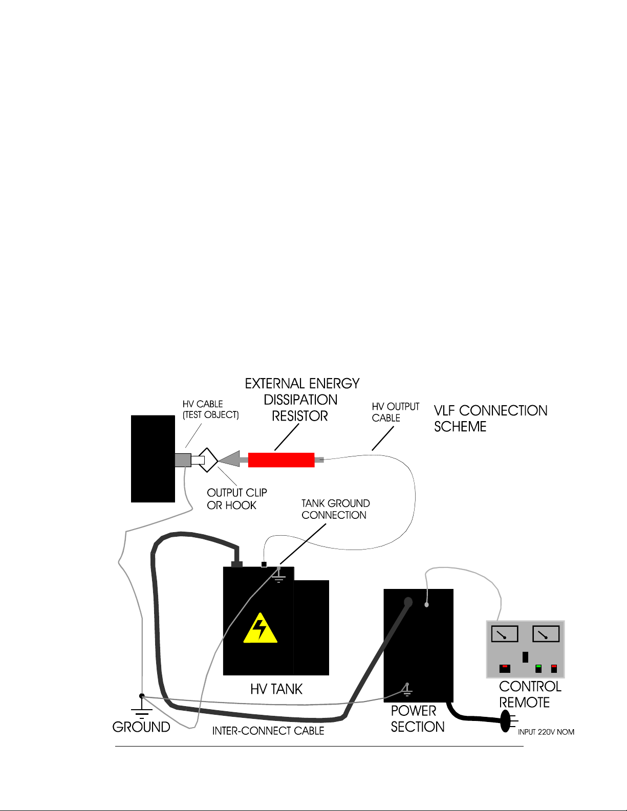
Typical VLF Connection Scheme 11
Operating the Equipment 11-17
Blank Page for Notes 18
S E C T I O N 3
Performing Special Operations 19
Voltmeter Re-calibration 19,20
Current Meter Re-calibration 20
Returned Material 21
Warranty 22,23

O P E R T O R M N U L
- 1 -
About the Operator Manual
Important
This Operator Manual describes the features and safe operation
of a High Voltage AC Test Set. The instructions are intended to be
clear and simple, but the operator must be trained and qualified
according to the customer’s established procedures for the use of
this t pe of equipment.
This Operator Manual is organized to provide information on the VLF-12011CM in steps that
familiarize the ne operator ith the entire scope of operation of this test set.
Section 1: Specifications and Controls.
Section 2: Setup and Operation.
Section 3: Performing Special Operations.
The Functions, Features, and Specifications of the VLF Series of AC Hipots are also discussed in the VLF
Brochure available from High Voltage, Inc.

O P E R T O R M N U L
2
22
2
General Information
This section familiarizes the operator ith the features and specifications of the
VLF Series of Very Low Frequency AC Hipots manufactured by HIGH VOLTAGE, INC.
Features and Specifications
The VLF-12011CM hipot test set provides true sine ave AC output voltage for the test of high
voltage cables and other capacitive loads.
Standard features of the VLF-12011CM AC Hipot
•
Sine ave output, 0.1, .05, .02 and .01Hz frequencies standard.
•
Continuously adjustable output voltage
•
Continuous duty rating
•
Fixed primary overload
•
“Zero Start” and External Interlock provision
•
Single-range voltmeter
•
Single range current meter ith capacitance measuring scale for determining best test frequency
•
Dual operating mode- Hipot/Burn for either hipotting ith an overload or burning ith current limiting
•
Three piece design, mounted on one Trolley.
•
Transit protected meter prevents damage bet een test sites in vehicle mounted installations
•
20 ft. interconnect cables ith grounds
•
100 ft. shielded X-Ray output cable AND 100 ft. Ground an Cable Reel
SECTION
1

O P E R T O R M N U L
3
33
3
•
Hook type output connector
•
Alligator clip type output connector
•
External Energy Dissipation Resistor
WARNING
DO NOT O ERATE THE VLF HI OT SET IF THE HIGH VOLTAGE TANK IS 5°
°°
° OR
MORE FROM LEVEL.
IF THE UNIT IS O ERATED OUT OF LEVEL, OVERHEATING AND INTERNAL ARCING MAY OCCUR.
DO NOT STORE OR TRANSPORT VLF HIGH VOLTAGE SECTION
ON IT’S SIDE

O P E R T O R M N U L
4
44
4
Operating Environment
Indoor/Outdoor-fair eather
Altitude: 100% of rating;Sea-level, up to 5000ft.(approx.1500M). The output
po er is de-rated 10% above 5000 ft. altitude, 20% above 12,000 ft.( approx.
3600M), and 30% above 15,000 ft.(approx. 4500M)
Storage Temperature: -20°C to 70°C(-4°F to 158°F)
Operating Temperature: -5°C to 45°C(22°F to 113°F) Output po er is de-
rated linearly by 15% from 30 to 45°C ambient.
Maximum Relative Humidity: 80% up to 31°C(88°F), decreasing linearly to
50% at 40°C(104°F)
Mains supply fluctuation: +/-10% of rated voltage
Installation: Category II
Pollution: Degree 2
WARNING
DO NOT O ERATE THE VLF HI OT SET IF THE HIGH VOLTAGE TANK IS 5°
°°
° OR
MORE FROM LEVEL.
IF THE UNIT IS O ERATED OUT OF LEVEL, OVERHEATING AND INTERNAL ARCING MAY OCCUR.
DO NOT STORE OR TRANSPORT VLF HIGH VOLTAGE SECTION
ON IT’S SIDE

O P E R T O R M N U L
5
55
5
Safety Symbol Identification
Warning! lease refer to documentation before
operation
rotective Earth Terminal
Warning: Hazardous Voltage
O P E R T O R M N U L
6
66
6
MODEL VLF AC HI OT S ECIFICATIONS
VLF-12011CM( 120 kV,1.1 µF)
Input 230V +/-10%, 50/60 Hz, single phase, 30 A .
Output Sinusoidal 0-120 kVac peak, 0.1, .05, .02 and .01 Hz frequency
Duty Continuous
Test Capacitance .55µF @ .1 Hz, 1.1µF @ .05 Hz, 2.2 µF @ .02 Hz , 5.5µF@.01 Hz
Kilovoltmeter 3.5 in. , 0-120 PEAK KILOVOLTS
Remote Control Size
Po er Section Size
High Voltage Tank size
17 x 11d x 9.5 high
20 x 14d x 27 high
26 x 26d x 22high
Control Case Wt.
Po er Section Wt.
HV Tank Wt.
20 lbs. (9kg)
160 lbs. (73kg)
390 lbs. (177kg)
765 lbs. (347kg) on Platform Truck ith 100ft. Cable Reel Assembly
Interconnect cable
length
Output cable length
20 ft.(STANDARD)
Shielded X-Ray 100 ft.(STANDARD)
Table 1 VLF-12011CM Specifications
.
O P E R T O R M N U L
7
77
7
OUT UT
FREQUENCY
.05Hz .02Hz
.01Hz.1Hz
BURN
HI OT
OUT UT
MODE
FAULT/RESET
OS
NEG
SCO E
OUT UT
EXT
INTLK
METER
MODE
uF mA
CA
ZERO
CA ACITANCE
SCALE X10
X1
USH TO READ
CA ACITANCE
MEASUREMENT
HOT COM
MAIN
OWER
HIGH
VOLTAGE
RAISE
LOWER
OFF ON
TIMER
START
AC TEST SET VLF SERIES
LEASE REFER TO
DOCUMENTATION
BEFORE O ERATION
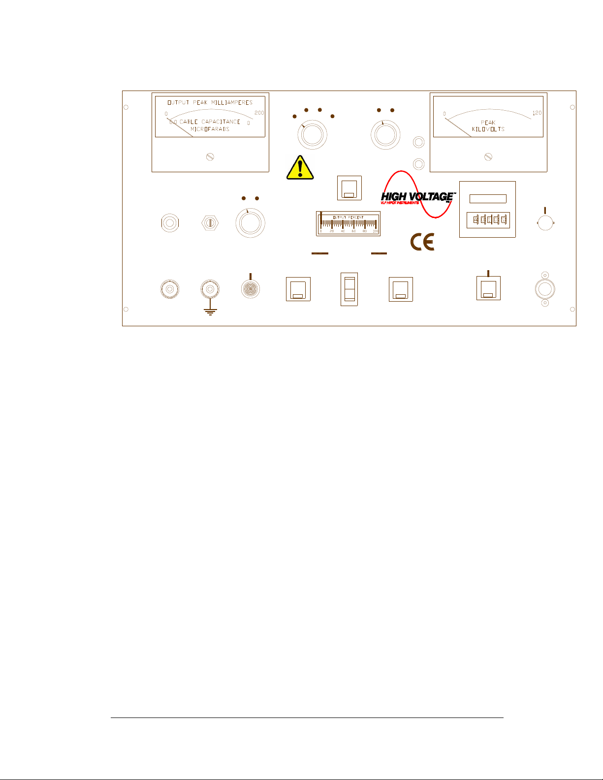
Figure 1 VLF Series front panel controls.
M A I N O W E R
The MAIN OWER neon lamp ill light hen the main po er circuit breaker is on in the po er
section and voltage is available to the input terminals.
E X T . I N T L K ( E X T E R N A L I N T E R L O C K )
The Ext. Intlk. connector is provided to allo for a normally open safety interlock s itch to
control the energizing of the high voltage output.
F A U L T / R E S E T
The FAULT/RESET pushbutton illuminates hen the primary current in the po er section has
exceeded the maximum limit. Its delayed trip allo s for the short term overload of the variable
transformer hile still providing proper protection. Depressing the pushbutton resets the circuit.
H I G H V O L T A G E O N / O F F
The HIGH VOLTAGE ON (OFF) pushbuttons activate (de-activate) the high voltage po er
circuits. The LED indicators provide long life positive indication of the circuit status. The RED
(ON) LED lights hen high voltage is energized, the GREEN (OFF) LED lights hen the high
voltage is de-energized.

O P E R T O R M N U L
8
88
8
H I G H V O L T A G E - R A I S E / L O W E R
The RAISE/LOWER control adjusts the output voltage by raising or lo ering the motorized
output control variable transformer. The OUT UT ERCENT meter above the RAISE/LOWER
control indicates the relative position of the variable transformer ith respect to the output
voltage. An automatic return to zero function at time of high voltage off ensures energizing of
high voltage at zero. The control must be at ZERO (0) to energize the high voltage circuits. The
output control must always be returned to zero at the completion of testing, prior to de-
energizing the output , allow the unit to cycle for 60 seconds to assure full discharge of
the capacitance in the load.
V O L T M E T E R
The KILOVOLT METER allo s for accurate output voltage readings. 1-% precision resistors
minimize the need for re-calibration due to aging shift. See Voltmeter Re-calibration in Section
3 for details on calibration.
C U R R E N T / C A A C I T A N C E M E T E R
The CURRENT/CA ACITANCE METER allo s for output current readings. The CURRENT
meter portion of this circuit is for observing the charge and discharge currents in the cable load.
1-% precision resistors minimize the need for re-calibration due to aging shift. The
CAPACITANCE scale on this meter is for measuring the load cable capacitance prior to test to
determine the best operating frequency for that particular cable run.
S C O E O U U T
The SCO E OUT UT allo s for accurate output voltage monitoring. This connector can be fed
into an oscilloscope for the looking at the actual output ave shape. The peak voltage
representing 50 kVac is 5 volts peak.
O U T U T F R E Q U E N C Y
The OUT UT FREQUENCY s itch adjusts bet een calibrated frequencies for testing loads
larger than normal .By allo ing slo er frequencies the output aveshape is maintained. Output
frequency choices are .1 Hz for .55 µF, .05 Hz for 1.1 µF, .02 Hz for 2.2 µF, and .01 for 5.5µF
load capacitance.
O U T U T M O D E
The OUT UT MODE is for choosing the operating mode of the overloads. When this control is
in the HI OT mode, the overload ill trip in case of an arc. When in the BURN mode, the
overload is still active. But, if an arc occurs, a reactor is s itched into the primary line to limit
primary current to the maximum rating for the unit allo ing the faulted cable to be burned to a
lo impedance fault. After a short is burned into the cable, conventional fault locating techniques
can be employed.

O P E R T O R M N U L
9
99
9
S T A R T T I M E R
The START TIMER s itch starts the d ell timer on the front panel to time test duration. The
timer can only be started hen high voltage is energized. The timer is reset only after the high
voltage is off and the START TIMER pushbutton is depressed.
Operation of the Timer In the VLF Hipot
The D ell Timer included in our VLF Series of AC Hipots ill function as an end of test alarm only. The timer ill start
upon initiation of the high voltage. The timing function ill count up to the preset value. Upon reaching the d ell time,
an alarm ill sound indicating the need to return the Output Control to zero. Turn off the high voltage, as noted later
in the Operating Manual, by allo ing the output discharge solenoids and polarity solenoids to cycle at least ten more
seconds (one full cycle).
To set the timer.
1) Press 'Mode'. When 'Timing Range' appears. Press '1' pushbutton. When desired range appears move to next
step.
2) Press 'Mode'. When 'UP/Do n Count' appears, press '1' to choose 'UP or 'DOWN'.
3) Press 'Mode". When 'Output Mode' appears, press '1' until Mode 'A' appears.
This setup should be retained in the timers memory. To change the time in the future see step 1.
M E T E R M O D E
The METER MODE s itch configures the current metering circuit for capacitance measuring or
for output current measurement.
C A A C I T A N C E ( U S H T O R E A D X 1 )
U S H B U T T O N
The USH TO READ X1 pushbutton changes the scale of the CAPACITANCE metering. The
modified Wheatstone Bridge incorporated in this circuit indicates x10 readings ithout
depressing the USH TO READ X1 pushbutton. When in the x10 scale and the reading is
below 6
µ
F, the PUSH TO READ X1 should be depressed to get an accurate load
capacitance measurement.
C A Z E R O
This potentiometer is for zeroing the capacitance range at full scale prior to measuring the cable
capacitance.

O P E R T O R M N U L
10
1010
10
C A A C I T A N C E M E A S U R E M E N T O S T S
These posts are for connecting the cable to the capacitance measuring circuit. The HOT post is
for the cable center conductor, the COM post is for the cable's grounded shield. Be sure the
cable is de-energized before connecting this lo voltage circuit or damage ill result. The
resulting capacitance measurement on the cable ill identify the best operating frequency for
that particular cable run. A frequency table is provided in the section O ERATING THE
EQUI MENT.
List of included components ith the VLF Hipot
Ext. Intlk. jumper plug
100 ft. long output X-Ray cable (Standard)
100 FT. Ground Lead
10 ft. interconnect cable ith grounds po er section to HV tank. (Standard)
20 ft. interconnect cable po er section to control box(Standard)
6 ft. BNC to BNC coax cable -scope to panel interconnect
20 ft. red and black test leads for capacitance measurement
External energy (current limit) dissipation resistor
WARNING
DO NOT O ERATE THE VLF HI OT SET IF THE HIGH VOLTAGE TANK IS 5°
°°
° OR
MORE FROM LEVEL.
IF THE UNIT IS O ERATED OUT OF LEVEL, OVERHEATING AND INTERNAL ARCING MAY OCCUR.
DO NOT STORE OR TRANSPORT VLF HIGH VOLTAGE SECTION
ON IT’S SIDE

O P E R T O R M N U L
11
1111
11
SETTING UP THE EQUIPMENT
The setup of this equipment has been minimized by consideration of the operator during design.
The VLF-12011CM three-piece construction on a roll around platform truck relieves the usual
installation and mobility obstacles for AC testing in the field or in a sub-station.
Select a level location
for the high voltage unit that ill allo easy hook-up to the test
cable. The cooling and filter assembly of the VLF series ill not operate properly if the high
voltage tank is placed on uneven ground. A maximum angle for correct operation is 5°. Blocking
the tank to a level condition is acceptable.
1.
Be sure that all the controls are off
,
in their de-energized or fully
counterclock ise position.
2.
Secure ground leads to the high voltage tank brass stud, and the
power section brass stud.
The Ground
leads should be of sufficient ampacit
to carr an expected fault currents from the load cable.
3.
Secure the interconnect cables from the power section to both the
control and the high voltage tank.
4.
Insert the coaxial output cable into the high voltage output
connector on the tank.
Tighten the clamping nut securely. The free hanging
lead from the center of the cable reel assembly connects to the high voltage tank.
Note:
The Output Cable from the cable reel must be uncoiled to the desired length
before the connection to the high voltage tank is made.
5.
Extend the GROUND CABLE on the reel to desired length
. Clamp the
orking end to the test cable shield. Clamp the reel end to a solid Station Ground.
6.
Insert the EXT INTLK plug into the socket on the control panel.
The
plug may also be ired to a normally open contact of a safety s itch for added
protection.
SECTION
2

O P E R T O R M N U L
12
1212
12
7.
Wire the input power terminal block to power as specified in Table
1, VLF-12011 specifications. ower wire should be rated for 30
Amps.
The setup of the VLF AC Test Set does not address the need for proper safety
grounding of the test cable load. The identification and disconnecting of cables from
service and the subsequent verification of the cables being de-energized may vary
for different types of tests or setups. lease consult the local codes where applicable
or reference the guidelines provided by your employer for maximum safety.
WARNING
DO NOT O ERATE THE VLF HI OT SET IF THE HIGH VOLTAGE TANK IS 5°
°°
° OR
MORE FROM LEVEL.
IF THE UNIT IS O ERATED OUT OF LEVEL, OVERHEATING AND INTERNAL ARCING MAY OCCUR.
DO NOT STORE OR TRANSPORT VLF HIGH VOLTAGE SECTION
ON IT’S SIDE
O P E R T O R M N U L
13
1313
13
Operating the Equipment
This section provides step-by-step instruction on various test methods. Many facilities
have their o n in-house test procedures, and this manual is not to supercede these.
The purpose of this section is to explain the capabilities of this test set in real- orld
applications.
When testing cables, either single or three phase, there are certain extra steps that must be
observed to ensure safe operation.
AC Cable Insulation Testing
1.
Ensure that all the steps listed in Setting up the Equipment have been
accomplished. Take special note to ground the po er section and the high voltage
tank to a solid earth ground.

O P E R T O R M N U L
14
1414
14
Caution!!
Before makin any cable connections, ensure that the cable
bein tested has been properly identified, de-ener ized,
and rounded!
2.
Make sure that all insulators, stress cones, and pot heads are clean and free of
moisture. This ill prevent flashover and minimize leakage.
3.
Isolate the far end of the conductors under test for the test voltage; that may mean
separating some of the conductors in a multi-conductor cable from each other and
their shields.
4.
Any conductors or ires in the cable or the vicinity not being tested must be
grounded to avoid a buildup of charge and possible shock hazard.
5.
Voltage must be applied according to specifications from the cable manufacturer or
any other applicable test standards
6.
Prior to connecting anything to the test sample, be sure the test sample is
identified, de-energized and grounded.
7.
First, the cable capacitance must be measured to determine the best operating
frequency. Place the control near the cable being tested.
8.
Connect the input po er terminal block to a grounded 220 v (+/-10%), 50/60 Hz
source. A generator is an acceptable po er source.
9.
Turn on the main circuit breaker. The MAIN POWER light ill illuminate at both the
po er section and the control.
10.
Operate the METER MODE to µ
µµ
µF position. Adjust the CA ZERO for full scale
deflection (ZERO) on the meter.
11.
Connect the HOT post to the center conductor of the test cable. Connect the COM
post to the grounded shield of the test cable. Read the CA ACITANCE scale(x10).
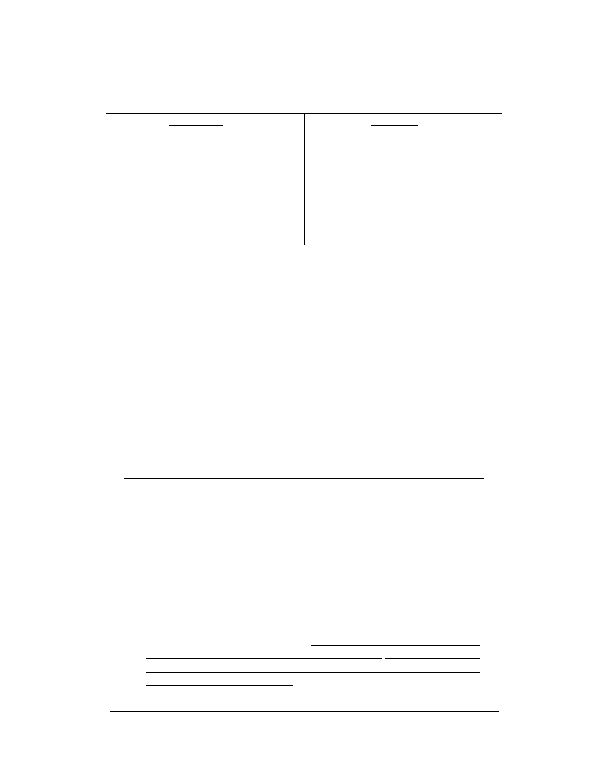
12.
If the reading is belo 6.0µF depress the x1 pushbutton. Then follo ing table
provides operating frequency versus capacitance.
O P E R T O R M N U L
15
1515
15
Capacitance Frequency
.55µF or less .1 Hz
1.1µF or less .05Hz
2.2µF or less .02Hz
5.5 µF or less .01Hz
13.
An oscilloscope (optional) can be connected to the SCO E OUT UT on the
control for ave shape monitoring. The oscilloscope should be properly grounded
and the input should be set to 1 volt/ division, the time base should be 5
seconds/division and the trigger should be set to roll display to vie the ave
shape. An oscilloscope ith signal memory display is best used for this application.
A BNC to BNC shielded jumper should be used for connection bet een the
SCO E OUT UT and the oscilloscope. A digital meter can be used to monitor this
connector. The voltage feedback calibration for this connector is 1 volt for 10 kV of
output.
* * * C A U T I O N * * *
O T E N T I A L L Y L E T H A L V O L T A G E S
M A Y B E R E S E N T
14.
Connect the output lead of the cable reel to the test sample through the External
Energy Dissipation Resistor. Be sure that there is enough clearance to grounded
objects for the expected test voltage. The minimum clearance in air is 10 kV
ac/inch.
15.
Place the OUT UT MODE in the HI OT position
16.
With the OUT UT control at zero (zero start interlock engaged), depress the HV
ON pushbutton. The HV ON light ill glo . At this time the pump and fan on the
high voltage section ill also energize. If this is the first test at this location,
leave the output control at zero and allow the pump to circulate oil for 15
minutes prior to raisin the output volta e and startin the test. This will
pur e air from the coolin system.

O P E R T O R M N U L
16
1616
16
17.
Increase the output by operating the HIGH VOLTAGE control to the RAISE
position until the desired output voltage is reached. Raising the output too fast ith
large capacitive loads may trip the output overload. Observe the OUT UT
ERCENT meter to rough in the set voltage. Please recognize that the output
cycle is: 100 seconds for a full sine ave @.01 Hz, 50 seconds fro a full sine ave
@ .02 Hz, 20 seconds for a full sine ave @ .05 Hz, and 10 seconds for a full sine
ave @ .1 Hz. . To set the output voltage you may need more than one cycle to
read the output accurately.
18.
18.18.
18.
Maintain the output voltage for the test time specified in your standard procedures.
19.
After the test is complete, depress the HIGH VOLTAGE control in LOWER
position, allo ing the load to return to zero and the unit to cycle for about 60 more
seconds prior to depressing the HV OFF pushbutton. Allo ing the unit to cycle for
some time allo s for the complete discharge of the load and avoiding the normal
self recharge that capacitive loads ill exhibit.
20.
If the test sample fails during the test, the overload circuit ill de-energize the high
voltage. Should an overload occur, the normal sine ave cycle is interrupted and
the load may bleed do n much more slo ly than hen the unit is cycling normally.
Depress the FAULT/RESET pushbutton to resume testing.,
21.
21.21.
21.
rior to removing the output cable from the load, observe that the output
voltmeter is at zero, and then use a GROUND STICK to positively ground the
test sample.
Note: Be sure to disconnect the output cable from the high
voltage tank before coiling the output cable onto the cable reel
assembly.
WARNING
DO NOT O ERATE THE VLF HI OT SET IF THE HIGH VOLTAGE TANK IS 5°
°°
° OR
MORE FROM LEVEL.
IF THE UNIT IS O ERATED OUT OF LEVEL, OVERHEATING AND INTERNAL ARCING MAY OCCUR.
DO NOT STORE OR TRANSPORT VLF HIGH VOLTAGE SECTION
ON IT’S SIDE

O P E R T O R M N U L
17
1717
17
Using the BURN MODE on AC Cables
1. Ensure that all the steps listed in Setting up the Equipment have been
accomplished. Take special note to ground the po er section and the high voltage
tank to a solid earth ground.
Caution!!
Before makin any cable connections, ensure that the cable
bein tested has been properly identified, de-ener ized,
and rounded!
2. Make sure that all insulators, stress cones, and pot heads are clean and free of
moisture. This ill prevent flashover and minimize leakage.
3. Isolate the far end of the conductors under test for the test voltage; that may mean
separating some of the conductors in a multi-conductor cable from each other and
their shields.
4. Any conductors or ires in the cable or the vicinity not being tested must be
grounded to avoid a buildup of charge and possible shock hazard.
5. Voltage must be applied according to specifications from the cable manufacturer or
any other applicable test standards
6. Prior to connecting anything to the test sample, be sure the test sample is
identified, de-energized and grounded.
7. First, the cable capacitance must be measured to determine the best operating
frequency. Place the control near the cable being tested.
8. Connect the input po er terminal block to a grounded 220 v (+/-10%), 50/60 Hz
source. A generator is an acceptable po er source.
9. Turn on the main circuit breaker. The MAIN POWER light ill illuminate at both the
po er section and the control.
10. Operate the METER MODE to µ
µµ
µF position. Adjust the CA ZERO for full scale
deflection (ZERO) on the meter.
11. Connect the HOT post to the center conductor of the test cable. Connect the COM
post to the grounded shield of the test cable. Read the CA ACITANCE scale(x10).
Other manuals for VLF Series
1
This manual suits for next models
1
Table of contents
Other High Voltage Power Supply manuals


