AC-PRO-II®Quick Start Manual Rev 2.0 www.utilityrelay.com
Page 2
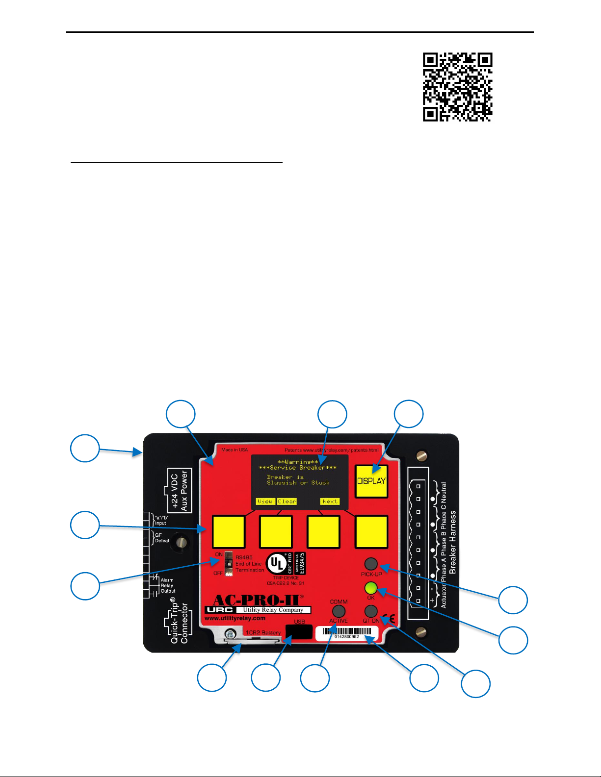
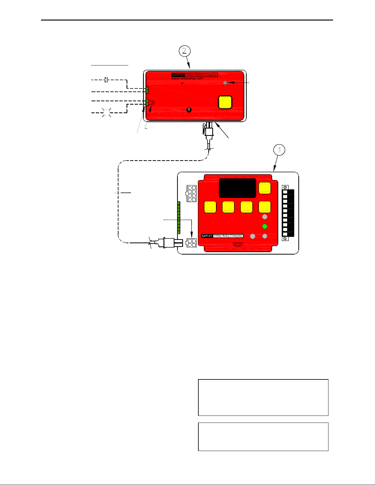
Refer to Figure A on page 1 for items below:
A. Local Display (rotatable)
The Local Display is normally mounted to the trip
unit. It can be rotated or separated from the trip
unit for specific breakers where space is limited.
B. OLED Display
The display is normally off. Pushing the
“DISPLAY”button (C) turns on the display. The
OLED displays the following information. Refer to
Section 5.0 for menu navigation.
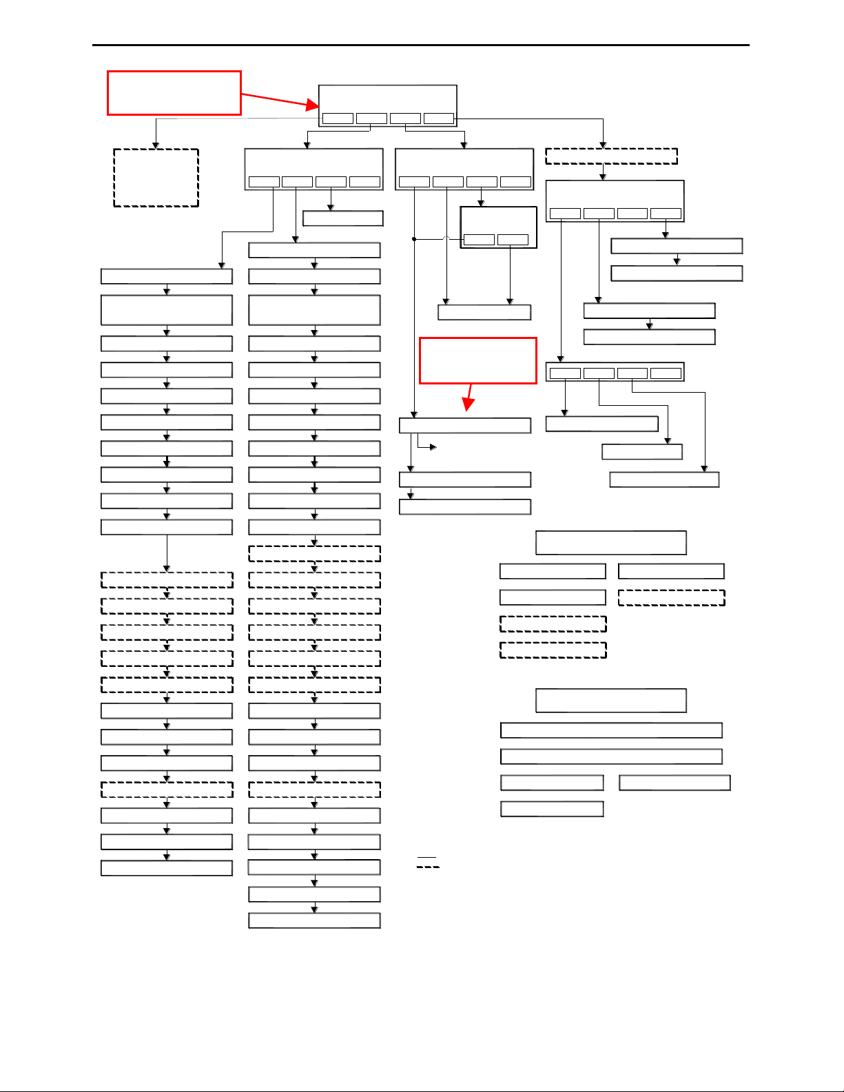
1) Power menu
2) Settings menu
3) Trip history menu
4) More Menu (Trip Unit info & Utilities)
5) Errors, alarms, and other messages
C. DISPLAY Push Button
Pushing the “DISPLAY”button will turn on the
display. If no buttons are pushed for 60 seconds,
the display will turn off.
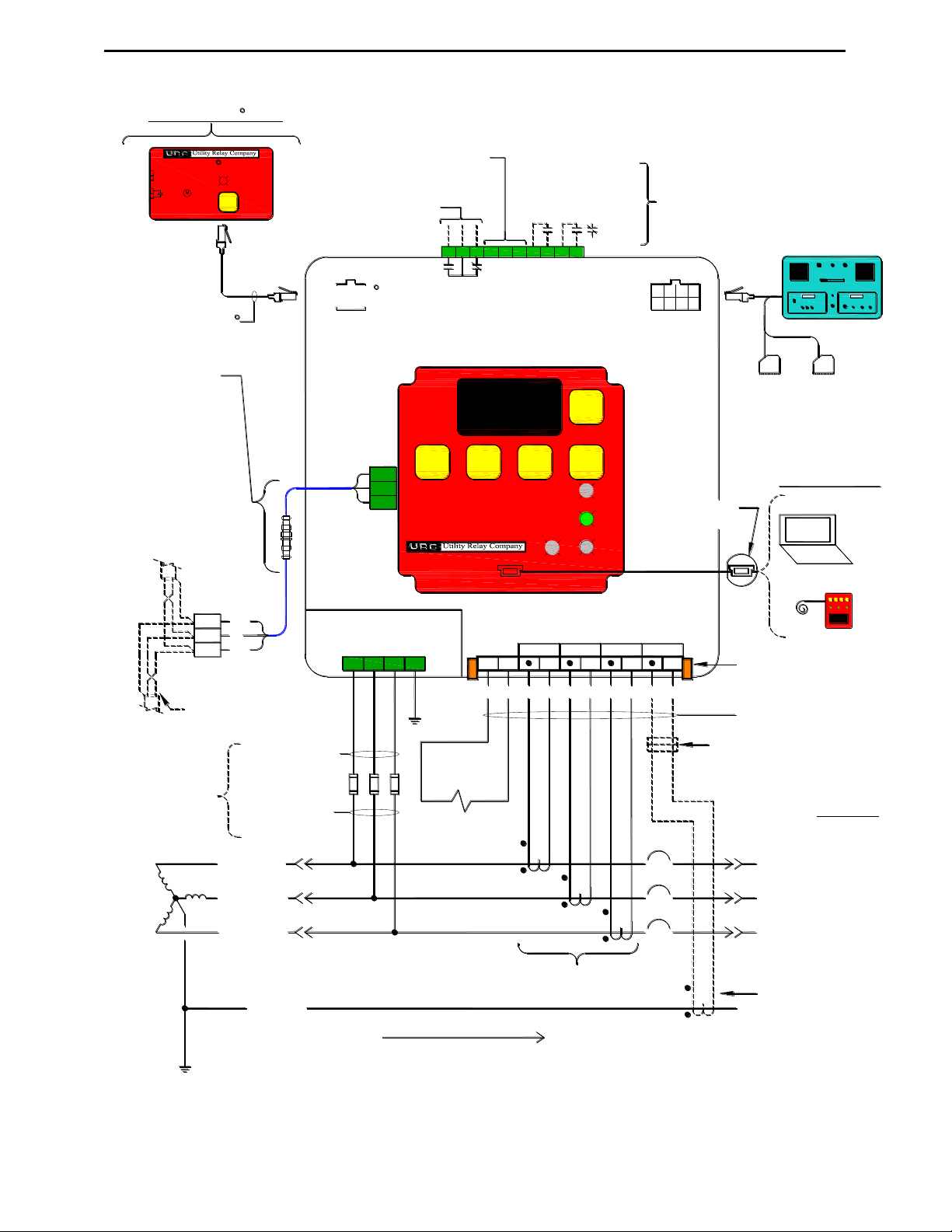
D. Removable wire cover
Cover with printed connection labels. See Section
6.0 for external connections (behind cover).
E. “Smart” Push Buttons
These push buttons perform the functions
indicated on the bottom of the OLED display.
These buttons are used for all menu navigation.
F. RS-485 Line Termination Switch
This switch should be placed in the ON position
only if the trip unit is the last in the RS-485
communications wiring run.
G. Red PICK-UP LED
This LED will illuminate if the current exceeds the
LT pick-up setting.
H. Green OK (Self-Test) LED
When the trip unit is powered up, this LED is on
unless a problem is detected. If the trip unit is not
powered up, the OK LED will not be on. If the
“DISPLAY” button is pressed, the OK LED should
come on, unless a problem is detected.
I. Battery Cover
To replace the battery, remove the single screw
and slide battery cover out, remove the old battery
and insert a new CR2, 3-Volt Lithium battery.
Replace the battery cover and screw.
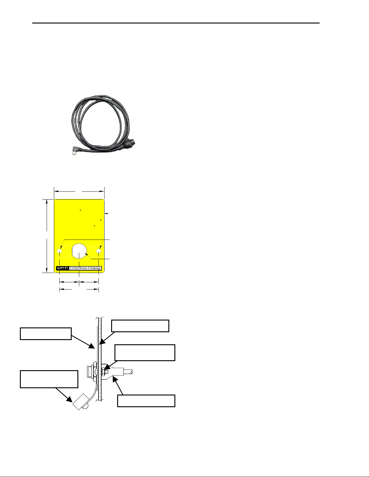
J. Mini-USB Port (shown with cover removed)
The electrically isolated mini-USB port is available
for connection to a laptop/ personal computer for
uploading & downloading of settings, information,
and firmware; SAFE-T-TRIP remote trip device
operation; or USB wall pack for auxiliary power.
K. COMM ACTIVE LED
The communications active LED illuminates when
the trip unit is transmitting information via
Communications.
L. AC-PRO-II Serial Number
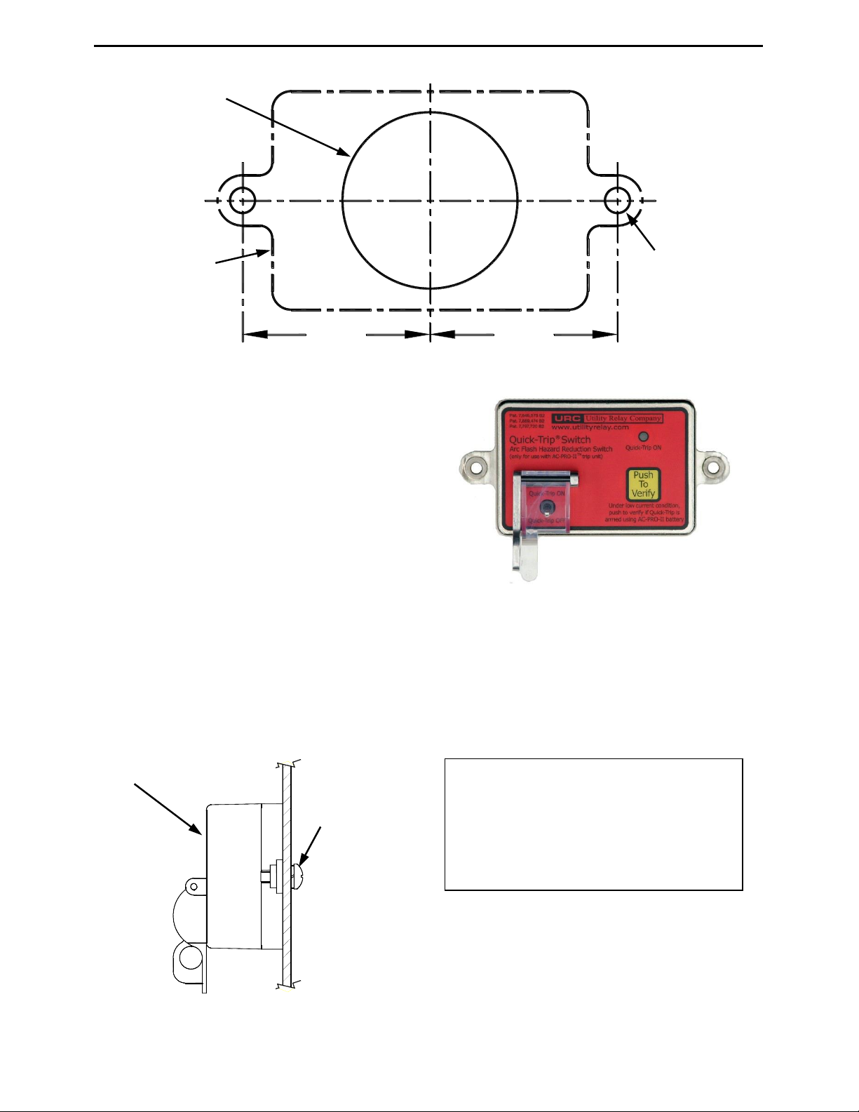
M. Quick-Trip LED (red)
This LED will illuminate if a Quick-Trip switch is
connected and on the ON position.
Before the AC-PRO-II trip unit is put into service, it must first
be commissioned so it will function. This requires the user to
enter all of the pick-up and delay settings into the unit.
The commissioning process normally takes less than a few
minutes to complete.
The AC-PRO-II can be commissioned using the local display
screen, or using the InfoPro-AC software application.
If the AC-PRO-II has not been commissioned, it will display
“Enter settings before placing into service”. Pressing the
“SET” button at this screen will begin the settings process.
For commissioning using the InfoPro-AC software
application, see Section 10.0, and the InfoPro-AC help guide
included in the application.
The security code is the last four (4) digits of the serial
number. See Error! Reference source not found. for
serial number location.
The time and date setting is accessed via the MORE menu,
by pressing the MORE button at the main screen, then the
time button, then the change button. The time and date
must be set after commissioning the AC-PRO-II or after
replacing the battery to ensure the time stamps (of trips and
on-demand waveforms) are recorded and are correct. In
order for the time and date to remain accurate after setting, a
fresh battery must be in place.
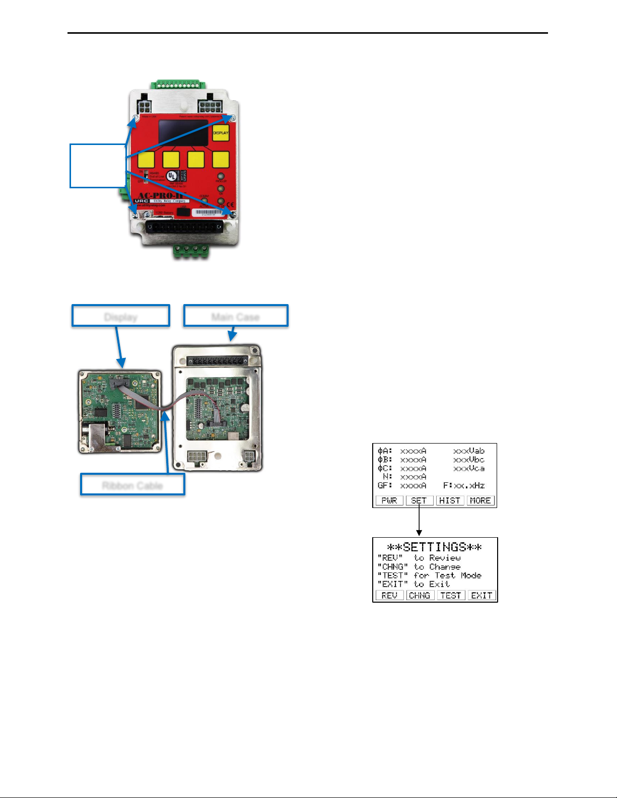
The AC-PRO-II trip unit consists of a main case and a
display case. The trip unit orientation can be modified by
rotating the display case. Refer to the AC-PRO-II retrofit kit
installation manuals for your breaker-specific trip unit
orientation.
To rotate the Display Case:
•The breaker must be out of service and de-energized
for safety.
•Ensure the person rotating the display is properly
grounded and takes special care to avoid static
discharge onto trip unit and display internal
components.
•Remove the black wiring cover by pulling the wiring
cover off the three (3) standoff posts.
•NOTE: the display case is connected to the main case
via the following:
oOne (1) Ribbon cable. See Figure B.
oFour (4) captive screws. See Figure A.
•Loosen the four (4) captive screws with a screwdriver.
•Leave the ribbon cable connected. Do not disconnect
the ribbon cable.
•Rotate the display to the position required for the
installation on the specific breaker. Be careful not to
damage, pinch, or disconnect the ribbon cable.
•Tighten the four (4) captive screws.
•Press the “DISPLAY” button and smart buttons to
confirm operation.
•Refer back to the AC-PRO-II retrofit kit Instructions for
additional breaker specific steps.