AFL MFIS User manual

MFIS Multi-Fiber Identification System
MFT Multi-Fiber Tracer
MFI Multi-Fiber Identifier
MFP Multi-Fiber Power Meter
Quick Reference Guide
www.AFLglobal.com or (800) 321-5298, (603) 528-7780
Test & Inspection
2
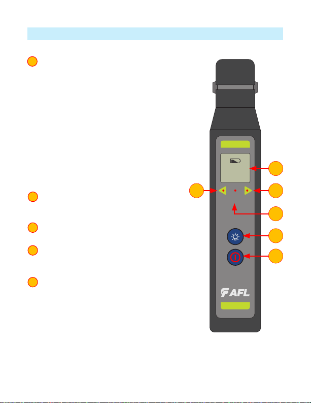
MFI Controls and Interfaces
1 Power Button provides two functions
as follows:
–Press and release the Power button to turn
the MFI identier On or Off (optionally
pull the trigger to activate the MFI). MFI
automatically turns Off after four (4)
minutes of inactivity.
–Press and hold the Power button during
power up until the letter “P” is displayed to
disable the Auto Off feature.
Note: MFI identier will stay powered up
until the Power button is pressed to turn
it Off.
2 Signal Detect Indicators. If valid signal
detected, both lights will ash and beeper
will sound once every 3 seconds.
3 No ID Indicator illuminates to indicate
absence of a valid optical signal.
4 Backlight Button. When the MFI identier
is turned On, press this button to toggle the
Backlight feature On or Off.
5 LCD Display
–The Battery icon appears on the MFI
display to indicate a “low battery”
condition. The discharged alkaline batteries
require replacement
–Will display Fiber Number if detected
–Will display “- - -” if no signal. (No signal
LED will illuminate as well).
1
2
3
4
5
ID
No
MFI
888
1
4
5
22
3
3
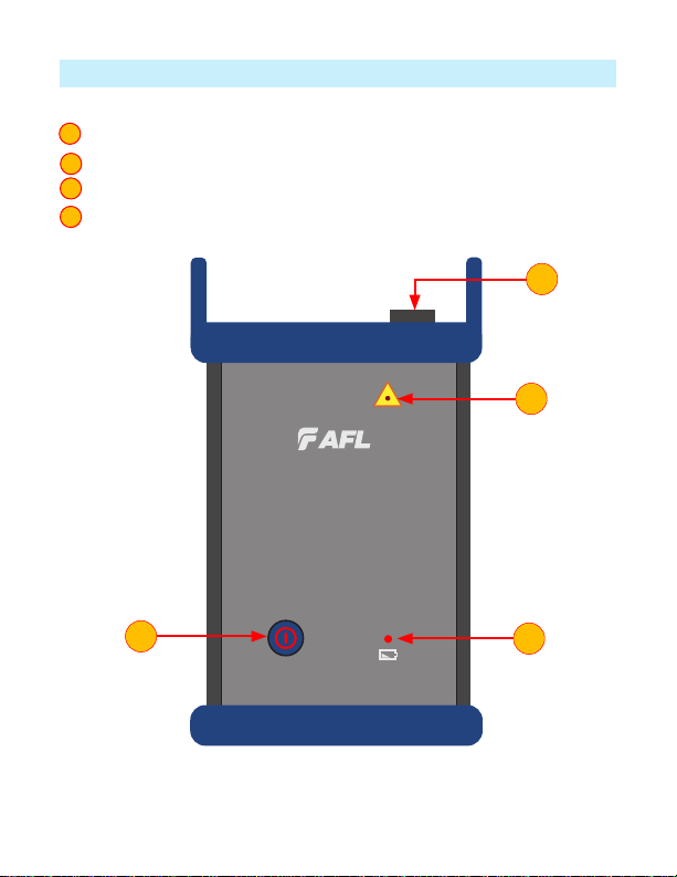
MFT Controls and Interfaces
1 MTP Connector: To plug in MTP cable.
2 Power Button: Press this button to turn the MFT ON or OFF.
3 Lasers Active Indicator illuminates to indicate that light source is turned On.
4 Low Battery Indicator illuminates to indicate a ‘low battery’ condition.
1
2
3
4
MFT
Multi-Fiber Tracer
2
3
4
1
4
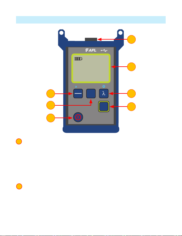
MFP Controls and Interfaces
1 Power Button provides two functions as follows:
–Press the Power button to turn the MFP power meter On or Off.
Notes: MFP will power up in the same mode it was set to when it was
powered Off. MFP automatically turns Off after ve (5) minutes of inactivity.
–Press and hold the Power button during power up until “P on” is displayed to
disable the Auto Off feature.
Note: MFP stays powered up until the Power button is pressed to turn it Off.
2 Fiber ID Button enables/disables Fiber ID mode.
–When MFP operates in standard power meter mode, pressing the Fiber ID
button will enable Fiber ID mode that allows MFP to report loss and ber ID
from MFT’s signal.
–Pressing the Fiber ID button again will disable Fiber ID mode and enable
standard power meter mode.
1
2
dBm
dB
W
Ref
Set
Fiber
ID
MFP
1550
Id
1.25 dB m
5
nm
1
43
6
7
2
5

5
MFP Controls and Interfaces
3 Wavelength/Backlight Button
Note: the Wavelength button only functions when the MFP is in standard power
meter mode. In Fiber ID mode the Wavelength button si disabled, as 1550 nm is
the only wavelength available in the Fiber ID test mode.
In the standard power meter mode the Wavelength/Backlight provides
two functions as follows:
–Press to cycle through the calibrated wavelengths.
–Press and hold to toggle the Backlight On or Off.
4 dB/dBm/µW Button provides two functions:
–Press to toggle test readings between insertion loss in dB and power in dBm.
–Press and hold to view power in µW.
5 Ref/Set Button works in both Fiber ID mode and standard power meter
mode. It provides two functions:
–Press to display the stored reference level for the currently selected
wavelength or multiple wavelengths.
–Press and hold until [HELD SET] is displayed to store the currently measured
level or multiple levels as the new reference levels. Once the new reference is
set, an MFP switches to the dB measurement mode.
6 LCD Display
–Battery status indicator - displays estimated battery life remaining.
The 3 bars indicate the charge level. When the battery is low, the battery
indicator will ash.
–In Fiber ID mode: displays loss and Fiber ID if detected or “- - -” if no signal.
–In standard power meter mode: displays wavelength and loss or power
measurements.
7 Optical Port - accepts AFL’s thread-on adapter cap.
3
4
5
6
7
6
Safety
Precautions
Caution: To avoid serious eye injury, never look directly into the optical outputs of
ber optic network equipment, test equipment, patch cords, or test jumpers. Always
assume that optical outputs are on.
It is important that the precautions given below be followed to ensure operating
efciency and to prevent inducing excessive signal loss during testing.
• The MFI utilizes light collecting optics that must be kept free of dirt, grease and
other contaminants.
• The MFI’s head is designed to guide the ber being tested to a precise position
relative to the optical assembly. The user should be careful to place bers gently
and in the provided ber groove. Forcing the ber into the head assembly or
misaligning it may induce optical losses above specications.
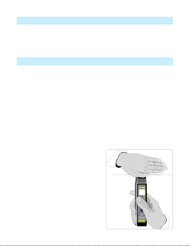
• Important: The MFI will not falsely indicate “Fiber ID”.
• Note: Bright ambient room or outdoor light can cause the MFI to give false “No
Signal”indications” when testing. To be sure that the ber is carrying ID trafc,
shield the optical assembly area of the MFI with your hand. Bright ambient light
can cause false “No Signal” readings,
however, low level trafc signals in color-
coated ber may not be detected.
7
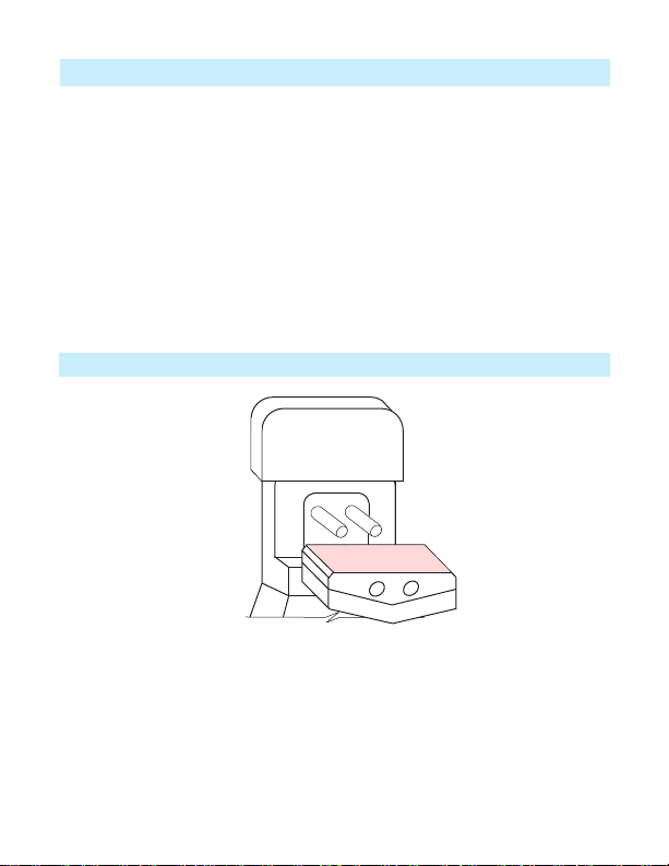
Ensuring the MFI Proper Plunger Position
It is very important to properly position the MFI plunger for testing 250 & 900 µm
coated and ribbon bers.
• Remove the plunger cover and observe the plunger position.
• Make sure the plunger is oriented correctly for the type of ber to be tested.
• If not, lift the plunger from the two retaining pins.
• Rotate the plunger such that the correct side is facing out and will be used for the
ber under test alignment.
• Replace the plunger and cover.
The “250/900/RIB” side faces out for the 250 µm and 900 µm coated and ribbon
bers testing
250 µm, 900 µm, Ribbon Fibers
250/900/RIB

8
Testing Fibers with MFT and MFI
Prior to testing, make sure the plunger is oriented correctly for the type of ber to
be tested.
• Power On the MFI identier by pressing the Power button . Alternatively the
MFI may be activated by pulling down the trigger. An audible tone generator will
“beep” when the unit is energized.
• Gently insert the ber to be tested into the ber groove located at the top of the
MFI’s head.
• Pull down and hold the trigger to depress the ber being tested against the
optical assembly.
• The MFI will start looking for Fiber ID bursts when the plunger has closed and the
ber is in the appropriate position.
Once the trigger is completely retracted, the MFI will discriminate transmitted
optical signals as follows:
–If the ber under test is active, the MFI display will show ber number if signal
is detected. Both arrows will alternately ash, and an audible tone will
beep every 3 seconds.
–When no signal is present, the MFI will illuminate the “No Signal” indicator
and show “ - - -” (no ber) on the display.
Additional Information for Ribbon Fibers Testing
Ribbon ber is typically comprised of 4, 8, or 12 bers with a 250 µm coating
attached together. The MFI will test ribbon bers, however, the user should be
aware of some limitations.
Warning: Can not be used on live ber network!
• The MFI will not isolate a specic ber from the group in a ribbon. If the ribbon
under test is carrying more than one MFT data burst signal, the MFI will not
function properly.
• Ribbon identication on bers 5,6,7,or 8 is the best since they are more
centrally located.

9
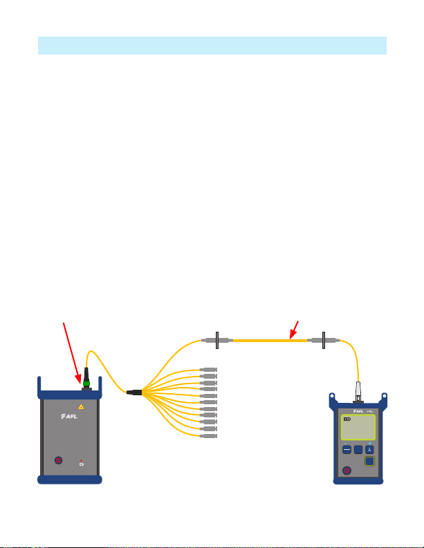
Identifying a Specific Fiber with MFT and MFI
During network installation, verication, and routing it is often necessary to verify
and reinstall mislabled bers or repair broken links.
When used in conjunction with an MFT, an MFI will detect if the ber under test
carry a signal emitted from MFT. An MFI will also display the ID of ber under test.
• Connect the MFT to the ber network to be tested.
• Turn On the MFT.
• Turn On the MFI and insert the ber to be tested in the ber groove.
• Pull down and hold the clamping trigger to depress the ber under test into the
optical assembly.
• When the MFT signal is detected, ber ID will display on the MFI. Verify if the
ber ID on display is matching ber under test.
MTP Fan-out
MTP Port
MFT MFI
Fiber/Ribbon Under Test
ID
No
MFI
888
MFT
Multi-Fiber Tracer
10
Identifying a Specific Fiber with MFP
When used in conjunction with an MFT, an MFP will detect if the ber under test
carry a signal emitted from MFT. An MFP will also display the Fiber ID and loss of the
ber under test.
• Connect the MFT to the ber network to be tested.
• Turn On the MFT.
• Turn On the MFP and verify that it is in the Fiber ID mode. If MFP is in standad
power meter mode, press the Fiber ID button to switch to the Fiber ID mode.
• Insert the ber to be tested in the test port.
• When the MFT signal is detected, ber ID will be displayed on the MFP along
with ber loss. Verify if the ber ID number on the MFP display matches the ber
number under test. Also verify if the ber loss is acceptable to test criteria.
MFT MFP
MFT
Multi-Fiber Tracer
dBm
dB
W
Ref
Set
Fiber
ID
MFP
1550
Id
1.25 dB m
5
nm
MTP Port Fiber/Ribbon Under Test
MTP Fan-out
11
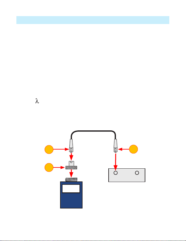
Measuring Optical Power with MFP
It is important to keep all optical connections and surfaces clean to ensure accurate
measurements and operation. Always clean all test jumpers before conducting tests.
1. Turn On the MFP and verify that it is in regular test mode. If MFP is in the Fiber
ID mode, press the Fiber ID button to switch to the regular power meter mode.
2. Select the appropriate ber optic test jumper. The ber type of this jumper must
be the same as the ber type normally connected to the output being measured.
3. Mount the appropriate adapter cap on the MFP port. This adapter cap must
match the connector on the end of the test jumper you will connect to the MFP.
4. Connect one end of the test jumper to the MFP adapter cap and the other end to
the optical output to be measured.
5. Press [ ] to select wavelength that matches the nominal wavelength of the
source being measured.
6. Press [dB/dBm/µW] to display power in [dBm] or press and hold to display power
in [µW].
4
Output Input
MFP
-20 dBm
Adapter cap
Fiber optic equipment
Test jumper
4
3

12
Testing Multimode or Single-mode Links with MFP
Step I - Set the Reference (One Jumper Method)
1. Turn on MFP and verify that it is in regular power meter test mode. Turn on OLS
and allow it to stabilize (minimum of 2 minutes).
2. Set both instruments to the desired wavelength.
3. Select transmit and receive jumpers (ber type must match link to be tested).
MM: Wrap and secure transmit jumper ve times around mandrel.
SM (TIA testing only): Make and secure 30 mm loop in a transmit jumper.
Clean both ends of the transmit jumper!
4. Connect the transmit jumper to the OLS output port (MM or SM respectively).
5. Mount adapter cap on the MFP (must match free connector on transmit jumper).
6. Connect transmit jumper (free end) to the MFP. Display optical power in [dBm].
7. If measured power is outside of the normal range (specied by manufacturer),
clean all ber connections or replace the transmit jumper. Repeat steps 4 - 7.
8. Set reference level:
–On MFP, press and hold [Ref/Set] until [HELD SET] is displayed to store
currently measured level as the new reference level.
–Once set, MFP switches to [dB] mode. MFP should display [0 dB] ± 0.05 dB.
OLS MFP
0 dB
Transmit jumper
Mandrel wrap - MM (shown),
or 30 mm loop - SM
5
7
6
4
13
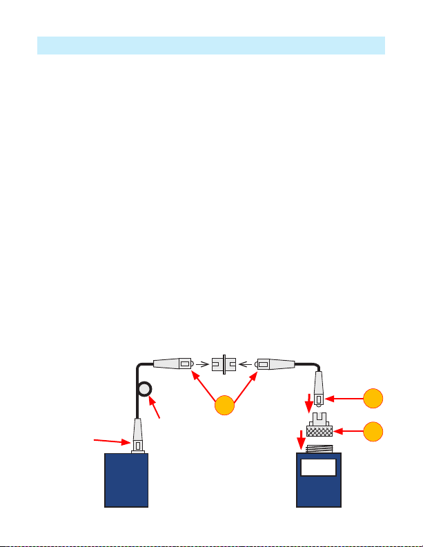
Testing Multimode or Single-mode Links
Step II - Verify Test Jumpers
9. Disconnect the transmit jumper from the MFP.
Do not disturb the transmit jumper at the OLS end!
10. If needed, change MFP adapter cap to match receive jumper connector.
Clean both ends of the receive jumper!
11. Connect receive jumper to the MFP.
12. Mate free ends of transmit and receive jumpers using the appropriate adapter.
13. Verify that the insertion loss of this mated connector pair is under 0.75 dB -
maximum allowed by TIA (AFL recommends 0.4 - 0.5 dB typical):
–Observe the displayed value - insertion loss of the test jumpers in [dB].
–If value is not acceptable, disconnect transmit and receive jumpers at the
adapter, clean free ends of both test jumpers and repeat steps 13 & 14.
–If value is still not acceptable, replace test jumpers and repeat steps 1-14.
14. If loss value is acceptable, disconnect transmit & receive jumpers at the adapter.
15. Move the MFP and OLS to opposite ends of the link to be tested.
OLS MFP
Mandrel wrap - MM (shown),
or 30 mm loop - SM
Transmit jumper
Do NOT
disturb this
connection
Adapter Receive jumper
13 12
11
0.4 dB
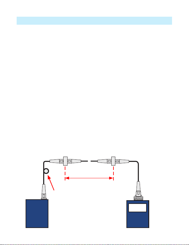
14
Testing Multimode or Single-mode Links
~
~
OLS MFP
2 dB
Link under test
Transmit jumper Receive jumper
Patch panelPatch panel
Mandrel wrap - MM (shown),
or 30 mm loop - SM
Step III - Measure Multimode Link Insertion Loss
16. Connect free ends of transmit and receive jumpers to the link under test.
Clean jumper end that connects to patch panel prior to every test!
17. MFP will measure and display the insertion loss of the link under test.
18. Record link insertion loss at the current test wavelength.
19. Repeat steps 17-19 for all links to be tested at the current wavelength.

15
Cleaning Optical Assembly
Battery Replacement
The optics of the MFI must be kept free from dirt or other contaminants to ensure
operating efciency and accurate Fiber ID detection.
Follow your company’s approved cleaning procedures.
AFL recommends using lint free FiberWipes™and FCC2 cleaning uid.
• Remove the MFI’s plunger cover.
• Lift the plunger from the two retaining pins.
• Dampen the wipe with the FPF1 or FCC2 cleaning uid and gently clean the
exposed prism and optical windows.
• Once completed, replace the plunger and plunger cover.
MFI
When a battery icon appears at the top of the MFI display, the 2 x 1.5 V AAA
alkaline batteries require replacement. To replace the discharged batteries:
• Remove the retaining screw and slide the battery plate away from the unit.
• Replace the discharged batteries.
• Replace the battery plate and retaining screw.
MFT and MFP
When the battery indicator lights on the MFT/MFP unit, the 2 x AA alkaline batteries
require replacement. To replace the discharged batteries:
• Turn the MFT/MFP unit Off.
• Remove any cable connected to the MFT/MFP.
• Remove the protective boot from the MFT/MFP unit.
• Open the battery retaining door located on the back of the unit.
• Replace the discharged batteries.
• Close battery retaining door.
• Insert the MFT/MFP unit back into its protective boot.

16
Warranty Terms and Conditions
Repair and Calibration
All AFL test equipment products are warranted for a period of (1) one year from the
date of delivery to the end user. AFL recommends calibrate MFIS system every (3)
three years.
NOTICE! AFL MFI, MFT, and MFP units contain no user serviceable parts. Except
for changing batteries, these units must be returned to AFL or authorized agents for
repair and calibration.
AFL Test and Inspection products are warranted against defective material and
workmanship for a period of (1) one year from the date of delivery to the end user.
Optional Extended Warranty starts at the end of the standard (1) one year warranty
period. Any product that is found defective within the warranty period, will (at the
discretion of AFL) be repaired or replaced. Warranty will be voided if the product has
been repaired or altered by other than an authorized AFL repair facility or when it
has been subjected to misuse, negligence, or accident.
In no case shall AFL liabilities exceed the original purchase price.

Thank you for choosing AFL Test & Inspection!
www.AFLglobal.com or (800) 321-5298, (603) 528-7780
Test & Inspection
©2018 AFL , all rights reserved. MFIS-QRG-1ENG Revision AA, 2018-10-04
A
F
L
T
e
s
t
&
I
n
s
p
e
c
t
i
o
n
This manual suits for next models
3
Table of contents
Other AFL Test Equipment manuals

AFL
AFL M710 Series Installation instructions

AFL
AFL OPM Series User manual

AFL
AFL OLS1 User manual

AFL
AFL FOCIS Duel User manual

AFL
AFL OFI-BI User manual

AFL
AFL FlexScan FS300 User manual

AFL
AFL FlexScan FS200 OTDR User manual

AFL
AFL FOCIS WiFi2 User manual

AFL
AFL ROGUE cB1 User manual

AFL
AFL FOCIS Lightning 2 User manual


Popular Test Equipment manuals by other brands

Applent Instruments
Applent Instruments Anbai AT8612 user guide

Benetech
Benetech GM3125 user manual

Comelit
Comelit 41LTS000 Technical manual

Tektronix
Tektronix Keithley S500 Administrative guide

Leuze electronic
Leuze electronic DB 112 B Technical description

JONARD TOOLS
JONARD TOOLS TEP-200 instruction manual


