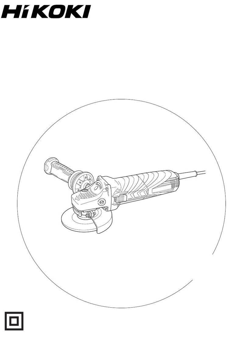
HIKOKI GP 3V User manual

1
6mm
88
17mm
12
34
56
00BookGP3VChS.indb100BookGP3VChS.indb12021/12/2714:21:032021/12/2714:21:03

2
楔形部分Tapered portion
弹性夹头Collet chuck
主轴Spindle
旋紧Tighten
弹性夹头Collet chuck
侧手柄Side handle
侧手柄套管Side handle sleeve
侧手柄把手Side handle grip
法兰部分Flange part
磨损极限Wear limit
碳刷号No. of carbon brush
弹簧Spring
碳刷Carbon brush
刷子搁放架Brush holder
转盘Dial
00BookGP3VChS.indb200BookGP3VChS.indb22021/12/2714:21:032021/12/2714:21:03

3
一般安全规则警告!阅读说明没有按照以下列举的说明而使用或操作将导致触电、着火和/或严重伤害。在所有以下列举的警告中术语“电动工具”指市电驱动(有线)电动工具或电池驱动(无线)电动工具。保存这些说明1) 工作场地a) 保持工作场地清洁和明亮。 混乱和黑暗的场地会引发事故。b) 不要在易爆环境,如有易燃液体、气体或粉尘的环境下操作电动工具。 电动工具产生的火花会点燃粉尘或气体。c)
让儿童和旁观者离开后操纵电动工具。
分心会使你放松控制。2) 电气安全a) 电动工具插头必须与插座相配。 绝不能以任何方式改装插头。 需接地的电动工具不能使用任何转换插头。
未经改装的插头和相配的插座将减少触电危险。
b) 避免人体接触接地表面,如管道、散热片和冰箱。
如果你身体接地会增加触电危险。
c) 不得将电动工具暴露在雨中或潮湿环境中。 水进入电动工具将增加触电危险。d) 不得滥用电线。 绝不能用电线搬运、拉动电动工具或拔出其插头。 让电动工具远离热、油、锐边或运动部件。 受损或缠绕的电线会增加触电危险。e) 当在户外使用电动工具时,使用适合户外使用的外接电线。 适合户外使用的电线将减少触电危险。3) 人身安全a) 保持警觉,当操作电动工具时关注所从事的操作并保持清醒。 切勿在有疲倦,药物、酒精或治疗反应下操作电动工具。 在操作电动工具期间精力分散会导致严重人身伤害。b) 使用安全装置。始终配戴护目镜。
安全装置,诸如适当条件下的防尘面具、防滑安全鞋、安全帽、听力防护等装置能减少人身伤害。
c) 避免突然起动。 确保开关在插入插头时处于关断位置。 手指放在已接通电源的开关上或开关处于接通时插入插头可能会导致危险。d) 在电动工具接通之前,拿掉所有调节钥匙或扳手。 遗留在电动工具旋转零件上的扳手或钥匙会导致人身伤害。e) 手不要伸得太长。 时刻注意脚下和身体平衡。 这样在意外情况下能很好地控制电动工具。f) 着装适当。 不要穿宽松衣服或佩带饰品。 让你的头发、衣服和袖子远离运动部件。 宽松衣服、佩饰或长发可能会卷入运动部件。g) 如果提供了与排屑装置、集尘设备连接用的装置,则确保他们连接完好且使用得当。 使用这些装置可减少碎屑引起的危险。4) 电动工具使用和注意事项a) 不要滥用电动工具,根据用途使用适当的电动工具。 选用适当的设计额定值的电动工具会使你工作更有效、更安全。b) 如果开关不能接通或关断工具电源,则不能使用该电动工具。 不能用开关来控制的电动工具是危险的且必须进行修理。c) 在进行任何调节、更换附件或贮存电动工具之前,必须从电源上拔掉插头和/或将电池盒脱开电源。 这种防护性措施将减少电动工具突然起动的危险。d) 将闲置电动工具贮存在儿童所及范围之外,并且不要让不熟悉电动工具或对这些说明不了解的人操作电动工具。 电动工具在未经训练的用户手中是危险的。e) 保养电动工具。检查运动件的安装偏差或卡住、零件破损情况和影响电动工具运行的其他条件。 如有损坏,电动工具必须在使用前修理好。 许多事故由维护不良的电动工具引发。f) 保持切削刀具锋利和清洁。 保养良好的有锋利切削刃的刀具不易卡住而且容易控制。g) 按照使用说明书以及打算使用的电动工具的特殊类型要求的方式,考虑作业条件和进行的作业来使用电动工具、附件和工具的刀头等。 将电动工具用作那些与要求不符的操作可能会导致危险情况。00BookGP3VChS.indb300BookGP3VChS.indb32021/12/2714:21:042021/12/2714:21:04

4
5) 维修a) 将你的电动工具送交专业维修人员,必须使用同样的备件进行更换。 这样将确保所维修的电动工具的安全性。注意事项不可让儿童和体弱人士靠近工作场所。应将不使用的工具存放在儿童和体弱人士接触不到的地方。砂磨操作的通用安全警告a) 该电动工具是用于实现砂轮机功能的。阅读随该电动工具提供的所有安全警告、说明、图解和规定。 不了解以下所列所有说明将导致电击、着火和/或严重伤害。b) 不推荐用该电动工具进行诸如砂光、刷光、抛光或切断等操作。 电动工具不按指定的功能去操作,可能会发生危险和引起人身伤害。c) 不使用非工具制造商推荐和专门设计的附件。 否则该附件可能被装到你的电动工具上,而它不能保证安全操作。d) 附件的额定速度必须至少等于电动工具上标出的最大速度。 附件以比其额定速度大的速度运转会发生爆裂和飞溅。e) 附件的外径和厚度必须在电动工具额定能力范围之内。 不正确的附件尺寸不能得到充分防护或控制。f) 砂轮、法兰盘、靠背垫或任何其他附件的轴孔尺寸必须适合于安装到电动工具的主轴上。 带轴孔的、与电动工具安装件不配的附件将会失稳、过度振动并会引起失控。g) 不要使用损坏的附。在每次使用前要检查附件,例如砂轮是否有碎片和裂缝,靠背垫是否有的裂缝、撕裂或过度磨损,钢丝刷是否松动或金属丝是否断裂。如果电动工具或附件跌落了,检查是否有损坏或安装没有损坏的附件。检查和安装附件后,让自己和旁观者的位置远离旋转附件的平面,并以电动工具最大空载速度运行1min。 损坏的附件通常在该试验时会碎裂。h)
戴上防护用品。根据适用情况,使用面罩、安全护目镜或安全眼镜。适用时,戴上防尘面具、听力保护器、手套和能挡小磨料或工件碎片的工作围裙。
眼防护罩必须挡住各种操作产生的飞屑。防尘面具或口罩必须能过滤操作产生的颗粒。长期暴露在高强度噪声中会引起失聪。i) 让旁观者与工作区域保持一安全距离。任何进入工作区域的人必须戴上防护用品。
工件或破损附件的碎片可能会飞出并引起紧靠着操作区域的旁观者的伤害。切割附件触及带电导线会使电动工具外露的金属零件带电,并使操作者触电。
j) 当在切割附件有可能切割到暗线或自身电线的场所进行操作时,只能通过绝缘握持面来握住电动工具。 切割附件碰到一根带电导线可能会使电动工具的外露金属零件带电并使操作者发生电击危险。k) 使软线远离旋转的附件。 如果控制不当,软线可能被切断或缠绕,并使得你的手或手臂可能被卷入旋转附件中。l) 直到附件完全停止运动才放下电动工具。 旋转的附件可能会抓住表面并拉动电动工具而让你失去对工具的控制。m) 当携带电动工具时不要开动它。 意外地触及旋转附件可能会缠绕你的衣服而使附件伤害身体。n) 经常清理电动工具的通风口。 电动机风扇会将灰尘吸进机壳,过多的金属粉末沈积会导致电气危险。o) 不要在易燃材料附件操作电动工具。 火星可能会点燃这些材料。p) 不要使用需用冷却液的附件。 用水或其他冷却液可能会导致电腐蚀或电击。反弹和相关警告反弹是因卡住或缠绕住的旋转砂轮、靠背垫、钢丝刷或其他附件而产生的突然反作用力。卡住或缠绕会引起旋转附件的迅速堵转,随之使失控的电动工具在卡住点产生与附件旋转方向相反的运动。例如,如果砂轮被工件缠绕或卡住,伸入卡住点的砂轮边缘可能会进入材料表面而引起砂轮爬出或反弹。砂轮可能飞向或飞离操作者,这取决于砂轮在卡住点的运动方向。在此条件下砂轮也可能碎裂。反弹是电动工具误用和/或不正确操作工序或条件的结果,可以通过采取以下给出的适当预防措施得以避免。a) 保持紧握电动工具,使你的身体和手臂处于正确状态以抵抗反弹力。如有辅助手柄,则要一直使用,以便最大限度控制住起动时的反弹力或反力矩。 如采取合适的预防措施,操作者就可以控制反力矩或反弹力。b) 绝不能将手靠近旋转附件。 附件可能会反弹碰到手。00BookGP3VChS.indb400BookGP3VChS.indb42021/12/2714:21:052021/12/2714:21:05

5
c) 不要站在发生反弹时电动工具可能移动到的地方。 反弹将在缠绕点驱使工具逆砂轮运动方向运动。d) 当在尖角、锐边等处作业时要特别小心。避免附件的弹跳和缠绕。 尖角、锐边和弹跳具有缠绕旋转附件的趋势并引起反弹的失控。e) 不要附装上锯链、木雕刀片或带齿锯片。 这些锯片会产生频繁的反弹和失控。对磨削的专用安全警告a) 只使用所推荐的砂轮型号和为选用砂轮专门设计的护罩。 不是为电动工具设计的砂轮不能充分得到防护,是不安全的。b) 砂轮只用作推荐的用途。例如:不要用切割砂轮的侧面进行磨削。 施加到砂轮侧面的力可能会使其碎裂。c) 始终为所选砂轮选用未损坏的、有恰当规格和形状的砂轮法兰盘。 合适的砂轮法兰盘支承砂轮可以减小砂轮破裂的可能性。切割砂轮的法兰盘可以不同于砂轮法兰盘。d) 不要使用从大规格电动工具上用剩的磨损砂轮。 用于大规格电动工具上的砂轮不适于较小规格工具的高速工况并可能会爆裂。研磨机一般安全使用说明- 确保砂轮上标注的速度等于或超过研磨机的额定速度;- 确保砂轮尺寸适合研磨机;- 应依照制造商的相关说明,妥善存放和谨慎使用砂轮;- 在使用之前检查砂轮,切勿使用破裂或有其他缺陷的产品;- 依照制造商的相关说明,确保安装的砂轮和安装点相适合;- 当相关研磨产品提供有吸墨纸时以及必要时,务必使用吸墨纸;- 在使用之前,确保研磨产品安装正确且拧紧,在无负载的情况下在安全位置运行工具 30 秒,如果出现明显震动或如果检测到其他缺陷,应立即停止。若出现这种情形,检查机器以查明原因;- 如果工具配有防护装置,切勿在没有防护装置的情况下使用工具;- 切勿使用单独的过渡衬套或转换器放置大孔径砂轮;- 若工具将安装带螺纹孔的砂轮,确保砂轮中的螺纹足以容纳轴长;- 确保工件得到正确支撑;- 侧面研磨时,切勿使用切断砂轮;- 确保在使用时产生的火星不会造成危险,如溅到人身上或点燃易燃物;- 在多尘环境中使用时,切勿挡住通风口。如需清理灰尘,应先从主电源断开工具(使用非金属物品),并避免损坏内部部件;- 务必使用护眼和护耳装置。应穿戴身体防护装备,如防尘罩、手套、头盔和围裙;- 应留意工具关闭后仍继续运转的砂轮。规 格型式GP3VGP5V电压(按地区)*(110 V, 120 V, 127 V, 220 V, 230 V, 240 V) 输入功率*760 W空载转速*7000 ~ 29000 转/分2000 ~ 8300 转/分额定速度*
30800
转/分
8820
转/分砂轮最大直径*25 mm50 mm弹性夹头容量**6 mm6 mm重量(不含线缆)1.8 kg1.9 kg* 当须改变地区时应检查产品上的铭牌。** 随地区不同而有变化。00BookGP3VChS.indb500BookGP3VChS.indb52021/12/2714:21:052021/12/2714:21:05

6
电子控制研磨机配备电子速度控制,可提供:○ 一直全速,在有效范围内直至额定负载。○ 软启动。○ 变速注:研磨机配备转速控制电路。由于使用情形和工作电压等原因,转速可能略有变动。标 准 附 件(1) 扳手(17 mm) ..................................................1(2) 扳手(12 mm) ..................................................1(3) 侧手柄 (有些地区可能不配备) .......................1标准附件可能不预先通告而径予更改。选购附件(分开销售)○ 弹性夹头 用于3 mm 轴 用于3.175 mm(1/8英寸)轴 用于6.35 mm(1/4英寸)轴 用于8 mm 轴軸 除轴孔外,尺寸及操作方法与6 mm 弹性夹头相同。 ○ 带有6 mm 轴的砂轮 所有砂轮的颗粒度都为WA,级别都为60,粘合度都为P,因此,都适用于普通钢和特殊钢的打磨。KA-4KA-5KA-8KA-12KA-13○ 带有3 mm 轴的砂轮 所有砂轮的颗粒度都为WA,级别都为80,粘合度都为P,因此,都适用于普通钢和特殊钢的打磨。KA-20KC-20KC-22KC-23KC-24○ 修整器○ 箱子选购附件可能不预先通告而径予更改。用 途○ 压力加工、冲模铸造及模制用冲模的抛光。○ 螺纹切割冲模、工件及其它小型零件的抛光。○ 工件及机器零件的内部打磨。作 业 之 前1. 电源 确认所使用的电源与工具铭牌上标示的规格是否相符。注:当连接了电源时,内置电子控制电路进入待机状态,研磨机略微发热,这是正常现象。注意使用时,不能由直流电源、油机发电机组、升压器或其他任何类型的变压器供电。否则,不仅可能造成研磨机损坏,还可能发生意外。2. 电源开关 确认电源开关是否切断。若电源开关接通,则插头插入电源插座时电动工具将出其不意地立刻转动,从而招致严重事故。3. 延伸线缆 若作业场所移到离开电源的地点,应使用容量足够、铠装合适的延伸线缆,并且要尽可能地短些。4. 安装砂轮 安装砂轮,使长度 小于15 mm。如果 大于15 mm,则将发生异常振动,不仅会损害机器,而且可能造成严重事故。 使 长度尽可能小。00BookGP3VChS.indb600BookGP3VChS.indb62021/12/2714:21:052021/12/2714:21:05

7注:○ 将直径小于常规轴直径(6 mm)的轴插入夹头时或在无任何东西插入的状况下,切勿旋紧弹性夹头,否则会损害弹性夹头。○ 安装带有轴的砂轮时,请在图1所示的楔形部分涂上少量的主轴油(或缝纫机油)后再旋紧弹性夹头。 当d = 6 mm,6.35 mm(1/4英寸),8 mm时,砂轮的D应小于每个型号砂轮的最大直径(GP3V: 25 mm, GP5V: 50 mm)。如果使用D大于每个型号砂轮最大直径(GP3V: 25 mm, GP5V: 50 mm) 的砂轮,则圆周速度将超过安全极限,砂轮将破裂。切勿使用这种砂轮。 距离L随D的不同而变化。请参考下表以决定L。 当d = 3 mm、3.175 mm(1/8英寸),D应小于10 mm。请参考下表以决定L。 使用图2所示的两个扳手,可以容易地装卸砂轮。(图2)GP3V (当 = 15 mm)d3 mm, 3.175 mm (1/8英寸)6 mm, 6.35 mm (1/4英寸)8 mmD 5 mm 6 mm 8 mm10 mm13 mm16 mm20 mm25 mm25 mmL10 mm13 mm16 mm13 mm40 mm40 mm25 mm25 mm32 mmGP5V (当 = 15 mm)d3 mm, 3.175 mm (1/8英寸)6 mm, 6.35 mm (1/4英寸)8 mmD5 mm6 mm8 mm10 mm13 mm16 mm20 mm25 mm32 mm38 mm25 mm32 mm38 mmL10 mm13 mm16 mm13 mm40 mm40 mm25 mm25 mm13 mm7 mm32 mm25 mm19 mm5. 调整转数 这些型号都配备电子无极变速驱动,可根据使用情况改变转数。 如果转动转盘(图6)并将刻度设在 6,则转数增加;如果转动并设在 1,则转数减少。 在使用前,使用转盘设置转数。这样做时,可将下表作为大致参考。
转盘使用转速 (
转/分
)GP3VGP5V1磨光,抛光700020002除去油漆或涂层1140032503除去锈1580045004除去毛刺2020058005研磨2460070506粗磨290008300
注:转动转盘刻度时,注意不要让值小于 1 或大于 6。6. 使用焊接装置时的注意事项 在焊接装置旁边使用研磨机时,转速可能变得不稳定。请勿在焊接装置旁边使用研磨机。7. 侧手柄的使用方法(图3) 确保使用侧手柄以避免发生严重的触电危险。 请按照以下步骤将侧手柄安装至机器上:(1) 拧松侧手柄把手,然后从侧手柄套管的法兰部分将侧手柄插入到机器的凸型托架部分。(2) 将侧手柄置于一个便于操作的位置,然后将侧手柄把手牢牢拧紧。使 用 方 法1. 开关操作(1) 将开关杆移到右侧(ON位置)时,电源便会接通;将开关杆移到左侧(OFF位置)时,电源便会关闭。(2) 安装新砂轮后第一次接通开关时,请将电磨机放在远离身体的地方,以免砂轮由于缺陷而破碎导致人身伤害。(3) 开始作业前,请将砂轮指向安全位置对机器进行测试。2. 操作注意事项(1) 将砂轮轻轻压向待打磨的材料。打磨材料时需要高速旋转。使用高速旋转的手提电磨机以使压力最小。注意:以全速(转盘刻度 6)以外的任何值使用工具时,由于转数减少,电机可能无法充分散热。这可能造成电机在过载保护机制发挥作用前燃烧和毁坏的风险。以全速(转盘刻度 6)以外的任何值使用工具时,务必使工具轻微作用于材料表面。00BookGP3VChS.indb700BookGP3VChS.indb72021/12/2714:21:062021/12/2714:21:06

8
(2) 砂轮的修整 装配上砂轮后,请用砂轮修整器修正砂轮中心的偏差。如果砂轮中心有偏差,不仅无法进行精确的抛光,而且还会使电磨机的振动加大,以致降低电磨机的精度和耐用性。 运行不畅或破损的砂轮会损坏抛光表面或降低打磨效率。因此,请经常用修整器修整砂轮。砂轮的选择方法砂轮的种类应根据需要打磨的材料而定。请选择适合打磨材料的砂轮。下表是砂轮和要打磨材料之间的大致关系。带有轴的小号砂轮适用于打磨较小表面。小号砂轮的尺寸和形状示于“选购配件”处。因砂轮轴的直径为3 mm,请使用HiKOKI经销商作为选购配件单独销售的用于3 mm 轴的弹性夹头。要打磨的材料颗粒度级别粘合度结构粘合剂软钢、硬钢、锻钢 WA60 ~ 80PmV铸铁C36M - OmV黄铜、青铜、铝C36J - KmV陶瓷器WA60 ~ 80MmV合成纤维C36K - MmV维 护 和 检 查1. 检查砂轮 检查砂轮确无破裂和表面缺陷。2. 检查安装螺钉 要经常检查安装螺钉是否紧固妥善。若发现螺钉松了,应立即重新扭紧,否则会导致严重的事故。3. 电动机的维护 电动机绕线是电动工具的心脏部。应仔细检查有无损伤,是否被油液或水沾湿。4. 检查碳刷(图4) 马达使用碳刷,它是消耗部品,因此使用过久的碳刷将会导致马达故障,用具有相同碳刷号的新碳刷去更换旧的,碳刷编号用数字表示碳刷何时用旧或接近于磨损极限。此外,要经常保持碳刷清洁以及保证它在刷握里能自由滑动。5. 碳刷的更换 (图5)<拆卸碳刷>(1) 松开固定尾盖的D4自攻螺丝后,拆下尾盖。(2) 使用附备的六角扳手或小螺丝刀拉起压住碳刷的弹簧边缘。然后,向刷握的外侧卸下弹簧边缘。(3) 从刷握的端子部拆下碳刷上的引线末端,然后,从刷握上拆下碳刷。<安装碳别>(1) 将碳刷的引线末端插入刷握的端子部。(2) 将碳刷插入刷握。(3) 用附备的六角扳手或小螺丝刀将弹簧边缘装回碳刷顶部。注:确保弹簧端头没有卡住输出端。(4) 安装尾盖,然后旋紧D4 自攻螺丝。6. 维修零部件一览表注意HiKOKI牌电动工具的维修、改造和检查须由经HiKOKI公司授权的维修中心进行。当要求维修或其他保养服务时,若将此零部件一览表与电动工具一起呈交给经HiKOKI公司授权的维修中心,将有助于维修或保养工作。在操作和维修电动工具时,必须遵守贵国制定的安全的有关规则和标准。改造HiKOKI牌电动工具经常加以改善和改造以采用最新的先进技术。因此,某些零部件可能变更,恕不另行通知。注:为求改进,本手册所载规格可能不预先通知而径予更改。00BookGP3VChS.indb800BookGP3VChS.indb82021/12/2714:21:062021/12/2714:21:06

9
GENERAL SAFETY RULES
WARNING!
Read all instructions
Failure to follow all instructions listed below may result in
electric shock, fire and/or serious injury.
The term “power tool” in all of the warnings listed below
refers to your mains operated (corded) power tool or battery
operated (cordless) power tool.
SAVE THESE INSTRUCTIONS
1) Work area
a) Keep work area clean and well lit.
Cluttered and dark areas invite accidents.
b) Do not operate power tools in explosive
atmospheres, such as in the presence of
flammable liquids, gases or dust.
Power tools create sparks which may ignite the dust
of fumes.
c) Keep children and bystanders away while
operating a power tool.
Distractions can cause you to lose control.
2) Electrical safety
a) Power tool plugs must match the outlet.
Never modify the plug in any way.
Do not use any adapter plugs with earthed
(grounded) power tools.
Unmodified plugs and matching outlets will reduce
risk of electric shock.
b) Avoid body contact with earthed or grounded
surfaces such as pipes, radiators, ranges and
refrigerators.
There is an increased risk of electric shock if your
body is earthed or grounded.
c) Do not expose power tools to rain or wet
conditions.
Water entering a power tool will increase the risk
of electric shock.
d) Do not abuse the cord. Never use the cord for
carrying, pulling or unplugging the power tool.
Keep cord away from heat, oil, sharp edges or
moving parts.
Damaged or entangled cords increase the risk of
electric shock.
e) When operating a power tool outdoors, use an
extension cord suitable for outdoor use.
Use of a cord suitable for outdoor use reduces
the risk of electric shock.
3) Personal safety
a) Stay alert, watch what you are doing and use
common sense when operating a power tool.
Do not use a power tool while you are tired
or under the influence of drugs, alcohol or
medication.
A moment of inattention while operating power
tools may result in serious personal injury.
b) Use safety equipment. Always wear eye
protection.
Safety equipment such as dust mask, non-skid
safety shoes, hard hat, or hearing protection used for
appropriate conditions will reduce personal injuries.
c) Avoid accidental starting. Ensure the switch is in
the offposition before plugging in.
Carrying power tools with your finger on the
switch or plugging in power tools that have the switch
on invites accidents.
d) Remove any adjusting key or wrench before
turning the power tool on.
A wrench or a key left attached to a rotating part
of the power tool may result in personal injury.
e) Do not overreach. Keep proper footing and
balance at all times.
This enables better control of the power tool in
unexpected situations.
f) Dress properly. Do not wear loose clothing or
jewellery. Keep your hair, clothing and gloves
away from moving parts.
Loose clothes, jewellery or long hair can be caught in
moving parts.
g) If devices are provided for the connection of
dust extraction and collection facilities, ensure
these are connected and properly used.
Use of these devices can reduce dust related
hazards.
4) Power tool use and care
a) Do not force the power tool. Use the correct
power tool for your application.
The correct power tool will do the job better and safer
at the rate for which it was designed.
b) Do not use the power tool if the switch does not
turn it on and off.
Any power tool that cannot be controlled with the
switch is dangerous and must be repaired.
c) Disconnect the plug from the power source
before making any adjustments, changing
accessories, or storing power tools.
Such preventive safety measures reduce the risk
of starting the power tool accidentally.
d) Store idle power tools out of the reach of children
and do not allow persons unfamiliar with the
power tool or these instructions to operate the
power tool.
Power tools are dangerous in the hands of
untrained users.
e) Maintain power tools. Check for misalignment or
binding of moving parts, breakage of parts and
any other condition that may affect the power
toolsʼoperation.
If damaged, have the power tool repaired before
use.
Many accidents are caused by poorly maintained
power tools.
f) Keep cutting tools sharp and clean.
Properly maintained cutting tools with sharp cutting
edges are less likely to bind and are easier to
control.
g) Use the power tool, accessories and tool bits
etc., in accordance with these instructions and
in the manner intended for the particular type
of power tool, taking into account the working
conditions and the work to be performed.
Use of the power tool for operations different from
intended could result in a hazardous situation.
5) Service
a) Have your power tool serviced by a qualified
repair person using only identical replacement
parts.
This will ensure that the safety of the power tool
is maintained.
PRECAUTION
Keep children and infirm persons away.
When not in use, tools should be stored out of reach of
children and infirm persons.
00BookGP3VChS.indb900BookGP3VChS.indb92021/12/2714:21:062021/12/2714:21:06
10
SAFETY WARNINGS COMMON FOR GRINDING
OPERATIONS
a) This power tool is intended to function as a grinder.
Read all safety warnings, instructions, illustrations
and specifications provided with this power tool.
Failure to follow all instructions listed below may result in
electric shock, fire and/or serious injury.
b) Operations such as sanding, polishing, wire
brushing or cutting-offare not recommended to be
performed with this power tool.
Operations for which the power tool was not designed
may create a hazard and cause personal injury.
c) Do not use accessories which are not specifically
designed and recommended by the tool
manufacturer.
Just because the accessory can be attached to your
power tool, it does not assure safe operation.
d) The rated speed of the accessory must be at least
equal to the maximum speed marked on the power
tool.
Accessories running faster than their rated speed can
break and fly apart.
e) The outside diameter and the thickness of your
accessory must be within the capacity rating of your
power tool.
Incorrectly sized accessories cannot be adequately
guarded or controlled.
f) The arbour size of wheels, flanges, backing pads or
any other accessory must properly fit the spindle of
the power tool.
Accessories with arbour holes that do not match the
mounting hardware of the power tool will run out of
balance, vibrate excessively and may cause loss of
control.
g) Do not use a damaged accessory. Before each use
inspect the accessory such as abrasive wheels for
chips and cracks, backing pad for cracks, tear or
excess wear, wire brush for loose or cracked wires.
If power tool or accessory is dropped, inspect for
damage or install an undamaged accessory. After
inspecting and installing an accessory, position
yourself and bystanders away from the plane of
the rotating accessory and run the power tool at
maximum no-load speed for one minute.
Damaged accessories will normally break apart during
this test time.
h) Wear personal protective equipment. Depending on
application, use face shield, safety goggles or safety
glasses. As appropriate, wear dust mask, hearing
protectors, gloves and workshop apron capable of
stopping small abrasive or workpiece fragments.
The eye protection must be capable of stopping flying
debris generated by various operations. The dust mask
or respirator must be capable of filtrating particles
generated by your operation. Prolonged exposure to high
intensity noise may cause hearing loss.
i) Keep bystanders a safe distance away from work
area. Anyone entering the work area must wear
personal protective equipment.
Fragments of workpiece or of a broken accessory may
fly away and cause injury beyond immediate area of
operation.
j) Hold power tool by insulated gripping surfaces only,
when performing an operation where the cutting
accessory may contact hidden wiring or its own
cord.
Cutting accessory contacting a “live” wire may make
exposed metal parts of the power tool “live” and shock
the operator.
k) Position the cord clear of the spinning accessory.
If you lose control, the cord may be cut or snagged
and your hand or arm may be pulled into the spinning
accessory.
l) Never lay the power tool down until the accessory
has come to a complete stop.
The spinning accessory may grab the surface and pull
the power tool out of your control.
m) Do not run the power tool while carrying it at your
side.
Accidental contact with the spinning accessory could
snag your clothing, pulling the accessory into your body.
n) Regularly clean the power tool’s air vents.
The motor’s fan will draw the dust inside the housing and
excessive accumulation of powdered metal may cause
electrical hazards.
o) Do not operate the power tool near flammable
materials.
Sparks could ignite these materials.
p) Do not use accessories that require liquid coolants.
Using water or other liquid coolants may result in
electrocution or shock.
KICKBACK AND RELATED WARNINGS
Kickback is a sudden reaction to a pinched or snagged
rotating wheel, backing pad, brush or any other accessory.
Pinching or snagging causes rapid stalling of the rotating
accessory which in turn causes the uncontrolled power tool
to be forced in the direction opposite of the accessory’s
rotation at the point of the binding.
For example, if an abrasive wheel is snagged or pinched by
the workpiece, the edge of the wheel that is entering into the
pinch point can dig into the surface of the material causing
the wheel to climb out or kick out. The wheel may either jump
toward or away from the operator, depending on direction
of the wheel’s movement at the point of pinching. Abrasive
wheels may also break under these conditions.
Kickback is the result of power tool misuse and/or incorrect
operating procedures or conditions and can be avoided by
taking proper precautions as given below.
a) Maintain a firm grip on the power tool and position
your body and arm to allow you to resist kickback
forces. Always use auxiliary handle, if provided, for
maximum control over kickback or torque reaction
during start-up.
The operator can control torque reactions or kickback
forces, if proper precautions are taken.
b) Never place your hand near the rotating accessory.
Accessory may kickback over your hand.
c) Do not position your body in the area where power
tool will move if kickback occurs.
Kickback will propel the tool in direction opposite to the
wheel’s movement at the point of snagging.
d) Use special care when working corners, sharp edges
etc. Avoid bouncing and snagging the accessory.
Corners, sharp edges or bouncing have a tendency to
snag the rotating accessory and cause loss of control or
kickback.
e) Do not attach a saw chain woodcarving blade or
toothed saw blade.
Such blades create frequent kickback and loss of
control.
SAFETY WARNINGS SPECIFIC FOR GRINDING
OPERATION
a) Use only wheel types that are recommended for
your power tool and the specific guard designed for
the selected wheel.
00BookGP3VChS.indb1000BookGP3VChS.indb102021/12/2714:21:062021/12/2714:21:06

11
Wheels for which the power tool was not designed cannot
be adequately guarded and are unsafe.
b) Wheels must be used only for recommended
applications. For example: do not grind with the
side of cut-offwheel.
Abrasive cut-offwheels are intended for peripheral
grinding, side forces applied to these wheels may cause
them to shatter.
c) Always use undamaged wheel flanges that are of
correct size and shape for your selected wheel.
Proper wheel flanges support the wheel thus reducing
the possibility of wheel breakage. Flanges for cut-off
wheels may be different from grinding wheel flanges.
d) Do not use worn down wheels from larger power
tools.
Wheel intended for larger power tool is not suitable for
the higher speed of a smaller tool and may burst.
GENERAL SAFETY INSTRUCTIONS FOR
GRINDERS
– Check that speed marked on the wheel is equal to or
greater than the rated speed of the grinder;
– Ensure that the wheel dimensions are compatible with
the grinder;
– Abrasive wheels shall be stored and handled with care in
accordance with manufacturer’s instructions;
– Inspect the grinding wheel before use, do not use
chipped, cracked or otherwise defective products;
– Ensure that mounted wheels and points are fitted in
accordance with the manufacturer’s instructions;
SPECIFICATIONS
Model GP3V GP5V
Voltage (by areas)* (110 V, 120 V, 127 V, 220 V, 230 V, 240 V)
Power Input* 760 W
No-Load Speed* 7000 – 29000 /min 2000 – 8300 /min
Rated speed* 30800 /min 8820 /min
Max. Wheel Diam.* 25 mm 50 mm
Collet chuck Capacity** 6 mm 6 mm
Weight (without cord) 1.8 kg 1.9 kg
* Be sure to check the nameplate on product as it is subject to change by areas.
** This varies depending on the area.
Electronic Control
The grinder has an electronic speed control which provides:
○full speed at all times in the range up to rated load.
○soft-start.
○variable speed
NOTE:
The grinder is equipped with a rotational speed control
circuit. The rotational speed may fluctuate slightly due to
the conditions of use and working voltage.
STANDARD ACCESSORIES
(1) Wrench (17 mm) ...........................................................1
(2) Wrench (12 mm) ...........................................................1
(3) Side handle (not included by areas)..............................1
Standard accessories are subject to change without notice.
– Ensure that blotters are used when they are provided
with the bonded abrasive product and when they are
required;
– Ensure that the abrasive product is correctly mounted
and tightened before use and run the tool at no load
for 30 s in a safe position, stop immediately if there is
considerable vibration or if other defects are detected.
If this condition occurs, check the machine to determine
the cause;
– If a guard is equipped with the tool never use the tool
without such a guard;
– Do not use separate reducing bushings or adapters to
adapt large hole abrasive wheels;
– For tools intended to be fitted with threaded hole wheel,
ensure that the thread in the wheel is long enough to
accept the spindle length;
– Check that the work piece is properly supported;
– Do not use cutting offwheel for side grinding;
– Ensure that sparks resulting from use do not create
a hazard e.g. do not hit persons, or ignite flammable
substances;
– Ensure that ventilation openings are kept clear when
working in dusty conditions, if it should become
necessary to clear dust, first disconnect the tool from
the mains supply (use non metallic objects) and avoid
damaging internal parts;
– Always use eye and ear protection. Other personal
protective equipment such as dust mask, gloves, helmet
and apron should be worn;
– Pay attention to the wheel that continues to rotate after
the tool is switched off.
OPTIONAL ACCESSORIES (sold separately)
○Collet chuck
for 3 mm shaft
for 3.175 mm (1/8”) shaft
for 6.35 mm (1/4”) shaft
for 8 mm shaft
Dimensions and handling methods other than the shaft
hole are the same as those for the 6 mm collet chuck.
○Wheels with 6 mm shaft
All wheels are provided with WA grain, 60 granding,
and P bonding and are suitable for grinding general and
special steel materials.
00BookGP3VChS.indb1100BookGP3VChS.indb112021/12/2714:21:062021/12/2714:21:06

12
KA-4 KA-5 KA-8 KA-12 KA-13
○Wheels with 3 mm shaft
All wheels are provided with WA grain, 80 granding and P
bonding and are suitable for grinding general and special
steel materials.
KA-20 KC-20 KC-22 KC-23 KC-24
○Dresser
○Case
Optional accessories are subject to change without notice.
APPLICATIONS
○Finishing of dies for press working, die casting and
moulding.
○Finishing of thread cutting dies, tools and other small
parts.
○Internal grinding of tools and machine parts.
PRIOR TO OPERATION
1. Power source
Ensure that the power source to be utilized conforms
to the power requirements specified on the product
nameplate.
NOTE:
When connected to the power supply, the built-in
electronic control circuit shifts to standby status and
the grinder becomes slightly warm, but this is not a
malfunction.
CAUTION
Do not operate from a direct current power source, engine
generator, booster or any other type of transformer.
Doing so may not only cause damage to the grinder, but
may lead to accidents.
2. Power switch
Ensure that the power switch is in the OFF position. If the
plug is connected to a receptacle while the power switch
is in the ON position, the power tool will start operating
immediately, inviting serious accident.
3. Extension cord
When the work area is removed from the power source.
Use an extension cord of sufficient thickness and rated
capacity. The extension cord should be kept as short as
practicable.
4. Installing a wheel
Install the wheel so that length is less than 15 mm. If is
longer, abnormal vibration will occur, and the machine is
not only negatively affected, but there is a possibility of a
serious accident.
Make the
as small as possible.
When d = 6 mm, 6.35 mm (1/4”), 8 mm, D of the wheel
should be less than the Max. wheel diam. of each models
(GP3V: 25 mm, GP5V: 50 mm). If a wheel with D more
than the Max. wheel diam. of each models (GP3V: 25
mm, GP5V: 50 mm) is used, the circumference speed
exceeds the safety limit and the wheel will break. Never
use such a wheel.
Distance L varies for D. Determine L referring to the table
below.
When d = 3 mm, 3.175 mm (1/8”), D should be less than
10 mm. Determine L referring to the table below.
Wheels can be simply attached and detached by using
the two wrenches (Fig. 2).
NOTE
○Do not tighten the collet chuck by inserting a shaft thinner
than the regular shaft diameter (6 mm) in the chuck or in
an empty condition. This practice will damage the collet
chuck.
○When installing a wheel with shaft, tighten the collet
chuck after applying a small quantity of spindle oil (or
sewing machine oil) to the tapered portion indicated in
Fig. 1.
GP3V (when = 15 mm)
d 3 mm, 3.175 mm (1/8”) 6 mm, 6.35 mm (1/4”) 8 mm
D 5 mm 6 mm 8 mm 10 mm 13 mm 16 mm 20 mm 25 mm 25 mm
L 10 mm 13 mm 16 mm 13 mm 40 mm 40 mm 25 mm 25 mm 32 mm
GP5V (when = 15 mm)
d 3 mm, 3.175 mm (1/8”) 6 mm, 6.35 mm (1/4”) 8 mm
D 5 mm 6 mm 8 mm 10 mm 13 mm 16 mm 20 mm 25 mm 32 mm 38 mm 25 mm 32 mm 38 mm
L 10 mm 13 mm 16 mm 13 mm 40 mm 40 mm 25 mm 25 mm 13 mm 7 mm 32 mm 25 mm 19 mm
00BookGP3VChS.indb1200BookGP3VChS.indb122021/12/2714:21:072021/12/2714:21:07

13
5. Adjusting the number of revolution
These models are equipped with an electronic infinite-
variable-speed drive and can change the number of
revolution according to a use.
If you turn and set the dial scale (Fig. 6) to 6, the number
of revolution increases, and if you turn and set it to 1, the
number of revolution decreases.
Before use, set the number of revolution using the dial. In
so doing, refer to the following table as a rough guide.
Dial Use Rotation speed (/min)
GP3V GP5V
1 Polishing, finishing 7000 2000
2Removal of paint or
coat 11400 3250
3 Removal of rust 15800 4500
4 Removal of burrs 20200 5800
5 Grinding 24600 7050
6 Rough grinding 29000 8300
NOTE: Use caution not to turn the dial scale to any value
below 1 or above 6.
6. Caution when using near welding equipment
When using the grinder in the immediate vicinity of
welding equipment, the rotational speed may become
unstable. Do not use the grinder near welding equipment.
7. Using the side handle (Fig. 3)
Be sure to use the side handle to avoid the risk of severe
electrical shock.
Attach the side handle to the machine as follows.
(1) Loosen the side handle grip and insert the side handle to
the nose bracket part of the machine from the flange part
of the side handle sleeve.
(2) Set the side handle to a position that is suited to the
operation and then securely tighten the side handle grip.
Materials to be ground Grain Grading Bonding degree Structure Bonding agent
Mild steel, hard steel,
forged steel WA 60 – 80 P m V
Cast iron C 36 M - O m V
Brass, bronze, aluminium C 36 J - K m V
Ceramic WA 60 – 80 M m V
Synthetic resin C 36 K - M m V
Small-scaled wheels with shaft are prepared for grinding
small surfaces. Their dimensions and shapes are shown in
“OPTIONAL ACCESSORIES”.
Since wheel shaft diameter is 3 mm, use the collet chuck
for 3 mm shaft sold separately by your HiKOKI dealer as an
optional accessory.
MAINTENANCE AND INSPECTION
1. Inspecting the wheel
Ensure that the wheel is free of cracks and surface
defects.
2. Inspecting the mounting screws
Regularly inspect all mounting screws and ensure that
they are properly tightened. Should any of the screws be
HOW TO USE
1. Switching operation
(1) When moving the switch lever to the right (ON side),
power is applied; when moving it to the left (OFF side),
power is switched off.
(2) When first turning on the switch after installing a new
wheel, hold the grinder away from your body to avoid any
danger of a wheel shattering due to an imperfection.
(3) Before starting, test the machine with the wheel pointed
in a safe direction.
2. Precautions on operation
(1) Lightly press the wheel to the material to be ground.
When grinding materials, high-speed revolution
is necessary. Use a hand grinder with high-speed
revolution, minimizing the pressing force.
CAUTION
When using the tool at any value except the full speed
(Dial scale 6), the motor cannot be sufficiently cooled due
to the decreased number of revolution.
This could result in the risk of burning and damaging the
motor before an overload protective mechanism starts to
function.
Make sure that you use the tool by lightly applying it to the
surface of material when you use it at any value except
the full speed (Dial scale 6).
(2) Dressing the wheel
After attaching a wheel, correct deflection of the wheel
center by using a dresser. If the wheel center is eccentric,
not only precise finishing cannot be achieved but also
grinder vibration increases, lowering grinder accuracy
and durability.
A clogged or worn wheel will spoil the finishing surface or
lower grinding efficiency. Occasionally dress the wheel
by applying the dresser.
WHEEL SELECTING METHOD
Types of wheels are varied according to the materials to be
ground. Select a wheel appropriate for the material to be
ground.
The following table is an out line of wheels and materials to
be ground.
loose, retighten them immediately. Failure to do so could
result in serious hazard.
3. Maintenance of the motor
The motor unit winding is the very “heart” of the power
tool.
Exercise due care to ensure the winding does not
become damaged and/or wet with oil or water.
4. Inspecting the carbon brushes (Fig. 4)
The motor employs carbon brushes which are
consumable parts. Since an excessively worn carbon
brush can result in motor trouble, replace the carbon
brushes with new ones having the same carbon brush
No. shown in the figure when it becomes worn to or near
the “wear limit”. In addition, always keep carbon brushes
clean and ensure that they slide freely within the brush
holders.
00BookGP3VChS.indb1300BookGP3VChS.indb132021/12/2714:21:072021/12/2714:21:07

14
5. Replacing a carbon brush (Fig. 5)
<Disassembly>
(1) Loosen the D4 tapping screw retaining the tail cover and
remove the tail cover.
(2) Use the auxiliary hexagonal wrench or small screwdriver
to pull up the edge of the spring that is holding down the
carbon brush. Remove the edge of the spring toward the
outside of the brush holder.
(3) Remove the end of the pig-tail on the carbon brush from
the terminal section of brush holder and then remove the
carbon brush from the brush holder.
<Assembly>
(1) Insert the end of the pig-tail of the carbon brush in the
terminal section of brush holder.
(2) Insert the carbon brush in the brush holder.
(3) Use the auxiliary hexagonal wrench or small screwdriver
to return the edge of the spring to the head of the carbon
brush.
NOTE:
Make sure the end of the spring is not holding the pig-tail.
(4) Mount the tail cover and tighten the D4 tapping screw.
6. Service parts list
CAUTION
Repair, modification and inspection of HiKOKI Power
Tools must be carried out by a HiKOKI Authorized
Service Center.
This Parts List will be helpful if presented with the tool to
the HiKOKI Authorized Service Center when requesting
repair or other maintenance.
In the operation and maintenance of power tools, the
safety regulations and standards prescribed in each
country must be observed.
MODIFICATIONS
HiKOKI Power Tools are constantly being improved
and modified to incorporate the latest technological
advancements.
Accordingly, some parts may be changed without prior
notice.
NOTE
Due to HiKOKI’s continuing program of research and
development, the specifications herein are subject to
change without prior notice.
00BookGP3VChS.indb1400BookGP3VChS.indb142021/12/2714:21:072021/12/2714:21:07

15
GP3V
Item
No. Part Name Q’TY
1
COLLET CHUCK
1
2 SPINDLE 1
3 BEARING LID (B) 1
4 BALL BEARING 6001VVCMPS2L 1
5 RING 1
6TAPPING SCREW
(W/SP. WASHER) D5 × 30 4
7 GUARD PLATE 1
8 NOSE BRACKET 1
9 BALL BEARING 6000VVCMPS2L 1
10 COUPLING 1
11 RETAINING RING FOR D8
SHAFT 1
12 SEAL LOCK SCREW
(W/SP. WASHER) M4
×
10 2
13 BALL BEARING 609VVC2PS2L 1
14 INNER COVER 1
15 HEX. SOCKET SET SCREW
M4
×
41
16
ARMATURE
1
17 FAN GUIDE 1
18 HEX. HD. TAPPING SCREW
D4
×
70 2
19
STATOR
1
20 DUST SEAL 1
21 BALL BEARING 608VVC2PS2L 1
22 HOUSING 1
23 SLIDE KNOB 1
25 NAME PLATE 1
26 BRUSH HOLDER 2
27 CARBON BRUSH 1
28 SPRING 2
29 BRAND LABEL 1
30 CARBON BRUSH 1
31 RUBBER RING 1
32 MAGNET 1
33 SPRING 1
34 SLIDE BAR 1
35 TERMINAL M4.0 1
Item
No. Part Name Q’TY
36 CONNECTOR 50091 1
37 PILLAR TERMINAL 1
38 EARTH TERMINAL 1
39 CORD CLIP 1
40 TAPPING SCREW
(W/FLANGE) D4 × 16 2
41 CORD ARMOR 1
42 SETTING LABEL (B) 1
43 TAPPING SCREW
(W/FLANGE) D4 × 20 3
44 CONTROLLER 1
45 NOISE SUPPRESSOR 1
46 TERMINAL 1
47 SWITCH 1
48 MACHINE SCREW
(W/WASHER) M3.5 × 6 2
49 TAIL COVER 1
50 CORD 1
501 WRENCH 1
502 WRENCH 1
503 SIDE HANDLE 1
504 FLANGED SLEEVE 1
505 SIDE HANDLE SLEEVE ASS'Y 1
00BookGP3VChS.indb1500BookGP3VChS.indb152021/12/2714:21:072021/12/2714:21:07

16
GP5V
Item
No. Part Name Q’TY
1 COLLET CHUCK 1
2 SPINDLE 1
3 BEARING LID(B) 1
4 BALL BEARING 6001VVCMPS2L 1
5 RING 1
6 NOSE BRACKET 1
7TAPPING SCREW
(W/SP. WASHER) D5 × 30 4
8
BALL BEARING 6000VVCM PS2L
1
9RETAINING RING FOR
D10 SHAFT 1
10 FIRST GEAR 1
11 RETAINING RING FOR
D8 SHAFT 1
12 RETAINING RING 1
13 SLOTTED HD. SCREW
(SEAL LOCK) M4 × 8 2
14 BALL BEARING 609VVC2PS2L 1
15 INNER COVER 1
16 HEX. SOCKET SET SCREW
M4 × 4 1
17 ARMATURE 1
18 FAN GUIDE 1
19 HEX. HD. TAPPING SCREW
D4 × 70 2
20 STATOR 1
21 DUST SEAL 1
22 BALL BEARING 608VVC2PS2L 1
23 HOUSING 1
24 SLIDE KNOB 1
26 NAME PLATE 1
27 BRUSH HOLDER 2
28 CARBON BRUSH 1
29 SPRING 2
30 BRAND LABEL 1
31 CARBON BRUSH 1
32 RUBBER RING 1
33 MAGNET 1
34 SPRING 1
35 SLIDE BAR 1
Item
No. Part Name Q’TY
36 TERMINAL M4.0 (10 PCS.) 1
37 CONNECTOR 50091 (10 PCS.) 1
38 PILLAR TERMINAL 1
39 EARTH TERMINAL 1
40 CORD CLIP 1
41 TAPPING SCREW
(W/FLANGE) D4 × 16 2
42 CORD ARMOR 1
43 SETTING LABEL(B) 1
44 TAPPING SCREW
(W/FLANGE) D4 × 20 3
45 CONTROLLER 1
46 NOISE SUPPRESSOR 1
47 TERMINAL 1
48 SWITCH 1
49 MACHINE SCREW
(W/WASHER) M3.5 × 6 2
50 TAIL COVER 1
51 CORD 1
501 WRENCH 12MM 1
502 WRENCH 17MM 1
503 SIDE HANDLE 1
504 FLANGED SLEEVE 1
505 SIDE HANDLE SLEEVE ASS'Y 1
00BookGP3VChS.indb1600BookGP3VChS.indb162021/12/2714:21:072021/12/2714:21:07

17
00BookGP3VChS.indb1700BookGP3VChS.indb172021/12/2714:21:072021/12/2714:21:07

18
00BookGP3VChS.indb1800BookGP3VChS.indb182021/12/2714:21:072021/12/2714:21:07

201
Code No. C99195223 M
Printed in China
服务中心高壹工机商业 (上海) 有限公司上海市闵行区浦江工业园区三鲁路3585号7幢3楼制造商高壹工机 (马来西亚) 有限公司马来西亚柔佛州士乃第二工业区00BookGP3VChS.indb1900BookGP3VChS.indb192021/12/2714:21:072021/12/2714:21:07
Other manuals for GP 3V
2
This manual suits for next models
1
Table of contents
Other HIKOKI Grinder manuals

HIKOKI
HIKOKI G 18UDY User manual

HIKOKI
HIKOKI G 12SW User manual

HIKOKI
HIKOKI G 3610DB User manual

HIKOKI
HIKOKI G 23BYE User manual

HIKOKI
HIKOKI G 23SCY2 User manual

HIKOKI
HIKOKI G 10SQ User manual

HIKOKI
HIKOKI G 10VE2 User manual

HIKOKI
HIKOKI G 14DBL User manual

HIKOKI
HIKOKI G 12STA(S) User manual

HIKOKI
HIKOKI G 18DBL User manual

HIKOKI
HIKOKI G 13VA User manual

HIKOKI
HIKOKI G 10BYEQ User manual

HIKOKI
HIKOKI GP 2S2 User manual

HIKOKI
HIKOKI G 12SWA User manual

HIKOKI
HIKOKI G18UAY User manual

HIKOKI
HIKOKI G 18SE4 User manual

HIKOKI
HIKOKI G 12BYEQ User manual

HIKOKI
HIKOKI G 12SA4 User manual

HIKOKI
HIKOKI G 12STA User manual

HIKOKI
HIKOKI G 12SWS User manual