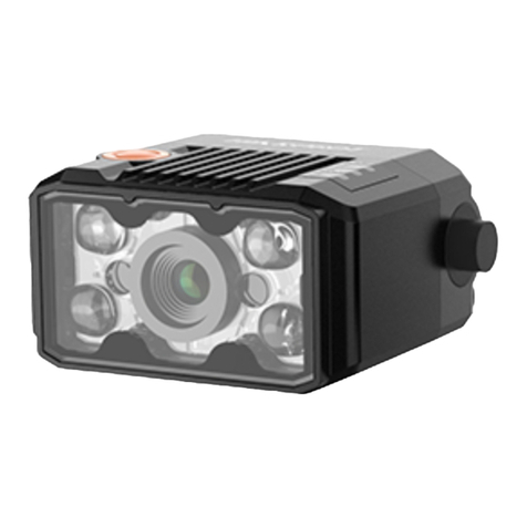
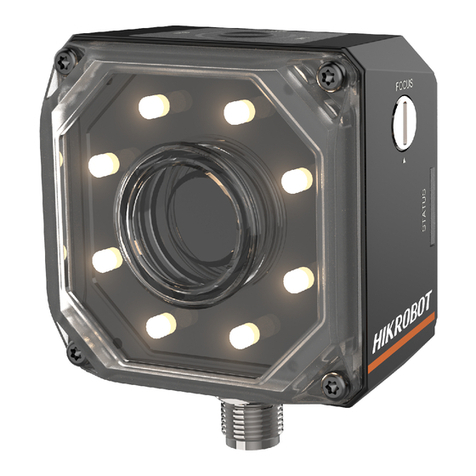
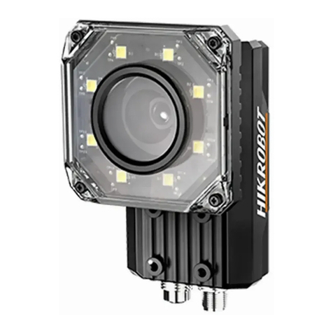
HikRobot ID2000 Series User manual

ID2000 Series Industrial Code Reader
User Manual

ID2000 Series Industrial Code Reader User Manual
i
Legal Information
© 2023 Hangzhou Hikrobot Co., Ltd. All rights reserved.
About this Manual
The Manual includes instructions for using and managing the Product. Pictures, charts,
images and all other information hereinafter are for description and explanation only. The
information contained in the Manual is subject to change, without notice, due to firmware
updates or other reasons. Please find the latest version of this Manual at the Hikrobot
website (https://www.hikrobotics.com/). Please use this Manual with the guidance and
assistance of professionals trained in supporting the Product.
Trademarks
and other Hikrobot's trademarks and logos are the properties of Hikrobot in
various jurisdictions. Other trademarks and logos mentioned are the properties of their
respective owners.
Disclaimer
TO THE MAXIMUM EXTENT PERMITTED BY APPLICABLE LAW, THIS MANUAL AND THE
PRODUCT DESCRIBED, WITH ITS HARDWARE, SOFTWARE AND FIRMWARE, ARE PROVIDED
"AS IS" AND "WITH ALL FAULTS AND ERRORS". HIKROBOT MAKES NO WARRANTIES,
EXPRESS OR IMPLIED, INCLUDING WITHOUT LIMITATION, MERCHANTABILITY,
SATISFACTORY QUALITY, OR FITNESS FOR A PARTICULAR PURPOSE. THE USE OF THE
PRODUCT BY YOU IS AT YOUR OWN RISK. IN NO EVENT WILL HIKROBOT BE LIABLE TO
YOU FOR ANY SPECIAL, CONSEQUENTIAL, INCIDENTAL, OR INDIRECT DAMAGES,
INCLUDING, AMONG OTHERS, DAMAGES FOR LOSS OF BUSINESS PROFITS, BUSINESS
INTERRUPTION, OR LOSS OF DATA, CORRUPTION OF SYSTEMS, OR LOSS OF
DOCUMENTATION, WHETHER BASED ON BREACH OF CONTRACT, TORT (INCLUDING
NEGLIGENCE), PRODUCT LIABILITY, OR OTHERWISE, IN CONNECTION WITH THE USE OF
THE PRODUCT, EVEN IF HIKROBOT HAS BEEN ADVISED OF THE POSSIBILITY OF SUCH
DAMAGES OR LOSS.
YOU ACKNOWLEDGE THAT THE NATURE OF INTERNET PROVIDES FOR INHERENT
SECURITY RISKS, AND HIKROBOT SHALL NOT TAKE ANY RESPONSIBILITIES FOR
ABNORMAL OPERATION, PRIVACY LEAKAGE OR OTHER DAMAGES RESULTING FROM
CYBER-ATTACK, HACKER ATTACK, VIRUS INFECTION, OR OTHER INTERNET SECURITY
RISKS; HOWEVER, HIKROBOT WILL PROVIDE TIMELY TECHNICAL SUPPORT IF REQUIRED.
YOU AGREE TO USE THIS PRODUCT IN COMPLIANCE WITH ALL APPLICABLE LAWS, AND
YOU ARE SOLELY RESPONSIBLE FOR ENSURING THAT YOUR USE CONFORMS TO THE
APPLICABLE LAW. ESPECIALLY, YOU ARE RESPONSIBLE, FOR USING THIS PRODUCT IN A
MANNER THAT DOES NOT INFRINGE ON THE RIGHTS OF THIRD PARTIES, INCLUDING
WITHOUT LIMITATION, RIGHTS OF PUBLICITY, INTELLECTUAL PROPERTY RIGHTS, OR
DATA PROTECTION AND OTHER PRIVACY RIGHTS. YOU SHALL NOT USE THIS PRODUCT
FOR ANY PROHIBITED END-USES, INCLUDING THE DEVELOPMENT OR PRODUCTION OF
WEAPONS OF MASS DESTRUCTION, THE DEVELOPMENT OR PRODUCTION OF CHEMICAL
OR BIOLOGICAL WEAPONS, ANY ACTIVITIES IN THE CONTEXT RELATED TO ANY NUCLEAR

ID2000 Series Industrial Code Reader User Manual
ii
EXPLOSIVE OR UNSAFE NUCLEAR FUEL-CYCLE, OR IN SUPPORT OF HUMAN RIGHTS
ABUSES.
THE PERFORMANCE DATA IN THIS PUBLICATION IS BASED ON HIKROBOT'S INTERNAL
RESEARCH/EVALUATION. ACTUAL DATA MAY VARY DEPENDING ON SPECIFIC
CONFIGURATIONS AND OPERATING CONDITIONS AND HIKROBOT SHALL NOT BEAR THE
CONSEQUENCES ARISING THEREFROM.
IN THE EVENT OF ANY CONFLICTS BETWEEN THIS MANUAL AND THE APPLICABLE LAW,
THE LATTER PREVAILS.
Regulatory Information
Note
These clauses apply only to the products bearing the corresponding mark or information.
FCC Information
Please take attention that changes or modification not expressly approved by the party
responsible for compliance could void the user’s authority to operate the equipment.
FCC Compliance
This equipment has been tested and found to comply with the limits for a Class A digital
device, pursuant to part 15 of the FCC Rules. These limits are designed to provide
reasonable protection against harmful interference when the equipment is operated in a
commercial environment. This equipment generates, uses, and can radiate radio frequency
energy and, if not installed and used in accordance with the instruction manual, may cause
harmful interference to radio communications. Operation of this equipment in a residential
area is likely to cause harmful interference in which case the user will be required to correct
the interference at his own expense.
FCC Conditions
This device complies with part 15 of the FCC Rules. Operation is subject to the following
two conditions:
●This device may not cause harmful interference.
●This device must accept any interference received, including interference that may cause
undesired operation.
EU Conformity Statement
This product and - if applicable - the supplied accessories too are
marked with "CE" and comply therefore with the applicable
harmonized European standards listed under the Directive
2014/30/EU(EMCD),Directive 2001/95/EC(GPSD) and Directive
2011/65/EU(RoHS).

ID2000 Series Industrial Code Reader User Manual
iii
2012/19/EU (WEEE directive): Products marked with this symbol
cannot be disposed of as unsorted municipal waste in the European
Union. For proper recycling, return this product to your local supplier
upon the purchase of equivalent new equipment, or dispose of it at
designated collection points. For more information see:
http://www.recyclethis.info
2006/66/EC (battery directive): This product contains a battery that
cannot be disposed of as unsorted municipal waste in the European
Union. See the product documentation for specific battery
information. The battery is marked with this symbol, which may
include lettering to indicate cadmium (Cd), lead (Pb), or mercury
(Hg). For proper recycling, return the battery to your supplier or to a
designated collection point. For more information see:
http://www.recyclethis.info
Symbol Conventions
The symbols that may be found in this document are defined as follows.
Symbol
Description
Danger
Indicates a hazardous situation which, if not avoided, will or
could result in death or serious injury.
Caution
Indicates a potentially hazardous situation which, if not avoided,
could result in equipment damage, data loss, performance
degradation, or unexpected results.
Note
Provides additional information to emphasize or supplement
important points of the main text.
Available Model
This manual is applicable to the ID2000 Series Industrial Code Reader.
Safety Instruction
These instructions are intended to ensure that the user can use the device correctly to avoid
danger or property loss.
●Read and follow these safety instructions before installing, operating and maintaining the
device.
●To ensure personal and device safety, when installing, operating, and maintaining the
device, follow the signs on the device and in the manual, and all safety instructions
described in the manual.
●The note, warning and danger items in the manual do not represent all the safety
instructions that should be observed, but only serve as a supplement to all the safety
instructions.

ID2000 Series Industrial Code Reader User Manual
iv
●The device should be used in an environment that meets the design specifications,
otherwise it may cause malfunctions, and malfunctions or component damage caused by
non-compliance with relevant regulations are not within the scope of the device's quality
assurance.
●Our company will not bear any legal responsibility for personal safety accidents and
property losses caused by abnormal operation of the device.
Caution:
●In the use of the device, you must be in strict compliance with the electrical safety
regulations of the nation and region.
●Use the power adapter provided by the official manufacturer, and the power supply should
meet LPS or PS2 requirements according to IEC 60950-1 or IEC 62368-1 standard. For the
specific requirements of the power adapter, please refer to the device’s specifications.
●To reduce the risk of fire or electric shock, do not expose the device to rain or moisture.
●Make sure that the device is firmly fixed when installing it in the use environment.
●The plug or socket of the device is for disconnecting the power supply, and do not cover
it.
●Make sure that the device is disconnected from power supply during wiring, disassembly
and other operations, and do not operate with electricity. Otherwise there will be a danger
of electric shock.
●Avoid aiming the lens at strong light (such as lighting, sunlight, or laser beams, etc.),
otherwise the image sensor will be damaged.
●Do not touch the image sensor directly. If cleaning is necessary, please slightly dampen a
soft clean cloth with alcohol and gently wipe off the dust. When the device is not in use,
please attach a dust cover to protect the image sensor.
●If the device does not work properly, please contact your dealer or the nearest service
center. Never attempt to disassemble the device yourself (we shall not assume any
responsibility for problems caused by unauthorized repair or maintenance).
●Please dispose of the device in strict accordance with the relevant national or regional
regulations and standards to avoid environmental pollution and property damage.
●Check whether the device’s package is in good condition, whether there is damage,
intrusion, moisture, deformation, etc. before unpacking.
●Check the surface of the device and accessories for damage, rust, bumps, etc. when
unpacking.
●Check whether the quantity and information of the device and accessories are complete
after unpacking.
●Store and transport the device according to the storage and transport conditions of the
device, and the storage temperature and humidity should meet the requirements.
●It is strictly prohibited to transport the device in combination with items that may affect
or damage the device.
●Please read the manual and safety instructions carefully before installing the device.
●The device should not be placed with exposed flame sources, such as lighted candles.
●Avoid installing the device in a vibration or shock environment, and keep it away from
electromagnetic interference sites (ignoring this may damage the device).

ID2000 Series Industrial Code Reader User Manual
v
●Do not directly touch the heat dissipation parts of the device to avoid burns.
●Do not install the indoor device in an environment where it may be exposed to water or
other liquids.
●Do not use the device in high temperature, low temperature or high humidity environment.
For specific temperature and humidity requirements, please refer to the device’s
specifications.
●Risk of explosion if battery is replaced by an incorrect type. Dispose of used batteries
according to the instructions.
Personnel Requirement
Quality requirements for installation and maintenance personnel: Qualification certificate or
working experience in weak current system installation and maintenance, and relevant
working experience and qualifications. Besides, the personnel must possess the following
knowledge and operation skills:
●The basic knowledge and operation skills of low voltage wiring and low voltage electronic
circuit connection.
●The ability to comprehend the contents of this manual.
Electromagnetic Interference Prevention
●When installing the device, if you cannot ensure that the device itself and all equipment
connected to the device are well grounded, you should isolate the device with an
insulating bracket.
●To avoid the accumulation of static electricity, ensure that other equipment (such as
machines, internal components, etc.) and metal brackets on site are properly grounded.
●The power cable, data cable, signal cable, etc. of the device must be wired separately.
Make sure to ground them if the wiring groove is used to separate the wiring and the
wiring groove is metal.
●During the installation and use of the device, high voltage leakage must be avoided.
●Use a figure-eight bundle method if the device cable is too long.
●Do not route the device together with other equipment (especially servo motors, high-
power devices, etc.), and control the distance between cables to more than 10 cm. Make
sure to shield the cables if unavoidable.
●The control cable of the device and the power cable of the industrial light source must be
wired separately to avoid bundled wiring.
●When connecting the device and metal accessories, they must be connected firmly to
maintain good conductivity.
●Use a shielded network cable to connect to the device. If you use a self-made network
cable, make sure that the shielding shell at the aviation head is well connected to the
aluminum foil or metal braid of the shielding cable.
●During the wiring process, evaluate the wiring space reasonably, and do not pull the cables
hard, so as not to damage the electrical performance of the cables.
●The unused cables of the device must be insulated.
●Use the power adapter to supply power to the device separately. If centralized power
supply is necessary, make sure to use a DC filter to filter the power supply of the device
separately before use.

ID2000 Series Industrial Code Reader User Manual
vi
●If the device is powered on and off frequently, it is necessary to strengthen the voltage
isolation, and consider adding a DC/DC isolation power supply module between the
device and the adapter.
Contact Information
Hangzhou Hikrobot Co., Ltd.
E-mail: tech_support@hikrobotics.com
Website: https://en.hikrobotics.com/

ID2000 Series Industrial Code Reader User Manual
vii
Contents
Chapter 1 Appearance .................................................................................................... 1
Chapter 2 Connector and Cable....................................................................................... 5
2.1 Type I Device with USB Interface.....................................................................................5
2.2 Type I Device with Fast Ethernet Interface and Type II Device...................................6
2.3 Type III Device.....................................................................................................................9
2.4 Type IV Device with Fast Ethernet Interface ............................................................... 11
2.5 Type IV Device with USB Interface ............................................................................... 13
Chapter 3 Electrical Feature and I/O Wiring ................................................................... 15
3.1 Electrical Feature and Wiring of Type I, III and IV Devices ....................................... 15
3.1.1 Input Signal........................................................................................................... 15
3.1.2 Output Signal........................................................................................................ 16
3.1.3 Bi-Directional Signal ........................................................................................... 17
3.1.4 Input Signal Wiring .............................................................................................. 19
3.1.5 Output Signal Wiring ........................................................................................... 21
3.2 Electrical Feature and Wiring of Type II Device.......................................................... 22
3.2.1 Input Signal........................................................................................................... 22
3.2.2 Output Signal........................................................................................................ 23
3.2.3 Input Signal Wiring .............................................................................................. 24
3.2.4 Output Signal Wiring ........................................................................................... 25
3.3 RS-232 Serial Port .......................................................................................................... 27
Chapter 4 Installation ................................................................................................... 28
4.1 Installation Preparation.................................................................................................. 28
4.2 Install Device.................................................................................................................... 28
Chapter 5 Device Connection ........................................................................................ 30
5.1 Install Client Software .................................................................................................... 30
5.2 Set PC Environment ........................................................................................................ 31
5.2.1 Turn off Firewall for Network Device ................................................................ 31
5.2.2 Set PC Network for Network Device ................................................................. 31
5.2.3 Check USB Drive for USB Device....................................................................... 32

ID2000 Series Industrial Code Reader User Manual
viii
5.3 Set Device Network......................................................................................................... 33
5.4 Connect Device to Client Software ............................................................................... 33
Chapter 6 Client Software Layout.................................................................................. 34
Chapter 7 Device Mode Settings ................................................................................... 36
Chapter 8 Device Settings............................................................................................. 38
8.1 Image Quality Settings ................................................................................................... 38
8.1.1 Set Image .............................................................................................................. 38
8.1.2 Set Polling............................................................................................................. 40
8.1.3 Set Light Source................................................................................................... 43
8.1.4 Set Lens Focus ..................................................................................................... 44
8.1.5 Set Self-Adaptive Adjustment ........................................................................... 48
8.1.6 Set Mirror X ........................................................................................................... 49
8.1.7 Set Test Pattern.................................................................................................... 50
8.2 Code Algorithm Settings ................................................................................................ 50
8.2.1 Add Code ............................................................................................................... 50
8.2.2 Set Code Reading ROI ......................................................................................... 51
8.2.3 Set 1D Algorithm Parameter .............................................................................. 55
8.2.4 Set 2D Algorithm Parameter .............................................................................. 55
8.2.5 Set 2D Code Quality Evaluation ......................................................................... 58
8.2.6 Set Code Score..................................................................................................... 59
8.3 Line Mode Settings ......................................................................................................... 60
8.4 Signal Input Settings ...................................................................................................... 61
8.4.1 Set Trigger Mode.................................................................................................. 61
8.4.2 Enable Internal Trigger Mode............................................................................. 62
8.4.3 Enable External Trigger Mode............................................................................ 62
8.4.4 Stop Trigger .......................................................................................................... 67
8.5 Signal Output Settings ................................................................................................... 71
8.5.1 Select Output Signal............................................................................................ 71
8.5.2 Enable Line Inverter............................................................................................. 71
8.5.3 Set Event Source.................................................................................................. 72
8.5.4 Set Buzzer ............................................................................................................. 75
8.6 Code Reading Result Settings....................................................................................... 75

ID2000 Series Industrial Code Reader User Manual
ix
8.6.1 Set Code Reading Result Output Mode............................................................ 75
8.6.2 Set Filter Rule ....................................................................................................... 76
8.6.3 Set Result Format ................................................................................................ 81
8.7 Communication Settings................................................................................................ 86
8.7.1 Smart SDK............................................................................................................. 86
8.7.2 TCP Client.............................................................................................................. 86
8.7.3 Serial ...................................................................................................................... 87
8.7.4 FTP ......................................................................................................................... 87
8.7.5 TCP Server............................................................................................................. 88
8.7.6 Profinet .................................................................................................................. 88
8.7.7 MELSEC or SLMP ................................................................................................. 89
8.7.8 Ethernet/IP............................................................................................................ 91
8.7.9 ModBus.................................................................................................................. 92
8.7.10 UDP ...................................................................................................................... 93
8.7.11 Fins....................................................................................................................... 94
8.7.12 USB ...................................................................................................................... 95
8.8 Set Multicast .................................................................................................................... 97
8.9 Main-Sub Networking..................................................................................................... 98
8.10 Contrast Control Settings .......................................................................................... 100
8.11 Statistics Information................................................................................................. 102
8.12 Event Report................................................................................................................. 103
8.13 User Set Customization ............................................................................................. 104
Chapter 9 Device Operation ........................................................................................ 105
9.1 Live View......................................................................................................................... 105
9.2 Enable Acquisition......................................................................................................... 105
9.3 Add Cross Line............................................................................................................... 106
9.4 Start Recording.............................................................................................................. 106
9.5 Split Window .................................................................................................................. 107
9.6 View Reports .................................................................................................................. 107
9.7 View Log.......................................................................................................................... 108
9.8 Set Time.......................................................................................................................... 108
9.9 Enable Device Auto Work ............................................................................................. 109

ID2000 Series Industrial Code Reader User Manual
x
Chapter 10 Device Maintenance.................................................................................. 110
10.1 Update Firmware......................................................................................................... 110
10.2 Reboot Device.............................................................................................................. 110
Chapter 11 FAQ (Frequently Asked Question) ............................................................. 112
11.1 Why the image is very dark? ..................................................................................... 112
11.2 Why the image's frame rate is very low in the live view? ..................................... 112
11.3 Why there is no device listed after I run the IDMVS client software? ................ 112
11.4 Why there is no image in the live view?................................................................... 113

ID2000 Series Industrial Code Reader User Manual
1
Chapter 1 Appearance
Note
Appearance here is for reference only. Refer to the device's specification for detailed
dimension information.
●Type I device is a vari focal device that supports adjusting focus manually via its focus
knob. This type device has two kinds of data interfaces, including fast Ethernet and USB.
●Type II and type IV devices are fixed focal device whose focus cannot be adjusted, and
type IV device has two kinds of data interfaces, including fast Ethernet and USB.
●Type III device is a vari focal device that adopts vari focal lens to adjust focus.
Figure 1-1 Appearance (Type I)

ID2000 Series Industrial Code Reader User Manual
2
Figure 1-2 Appearance (Type II)
Figure 1-3 Appearance (Type III)

ID2000 Series Industrial Code Reader User Manual
3
Figure 1-4 Appearance (Type IV)
Table 1-1 Component Description
No.
Name
Description
1
Focus Knob
It is used to adjust focal length manually.
Note
Only type I device has the focus knob.
2
Screw Hole
It is used to fix the device to the installation position.
●For type I, II and III devices, you should use M2 screw.
●For type IV device, you should use M3 screw.
3
Trigger Button
When the device is in trigger mode, press the button and the
device triggers once.
4
SR Cable
SR cable connector provides power, I/O, Ethernet, and serial port.

ID2000 Series Industrial Code Reader User Manual
4
No.
Name
Description
5
LNK Indicator
It is a network status indicator. The indicator is flashing green
when the network transmission is normal. Otherwise, it is unlit.
Note
Type IV device does not have a LNK indicator.
6
Status Indicator
For type I, II and III devices, it is a STS indicator. And for type IV
device, it is an OK/NG indicator.
●Regarding STS indicator, it is green when the device operates
normally, and it is red when the device is powered on or operation
error occurs.
●Regarding OK/NG indicator, it is red when the device is powered
on or operation error occurs, and it is unlit when the device
operates normally without reading codes. The indicator is green
lasting 0.5 s when the device reads codes successfully, and is
solid green when the device reads codes continuously.
7
PWR Indicator
It is a power indicator. The indicator is red during the device’s
power-on process. After the device is powered on, the indicator is
green.
8
Light Source
It is the LED light source used to provide light when the device
acquires images.
Note
The light source color is different by device models.
9
Sensor
It is used to acquire images.
10
Aiming Light
It helps to indicate the field of view and aim targets.
11
Buzzer
The buzzer beeps three times continuously when the device is
powered on, beeps twice when the device reads setting codes
successfully, and beeps once when the device reads codes
successfully.
Note
Only type IV device has a buzzer.

ID2000 Series Industrial Code Reader User Manual
5
Chapter 2 Connector and Cable
This section introduces the device’s connector on its SR cable and the supplied cable in the
package.
Note
The device’s connector and connector pin definitions may differ by device models.
2.1 Type I Device with USB Interface
Type I device with USB interface has a 17-pin M12 connector. Refer to the figure and table
below for connector pin definitions.
Figure 2-1 17-Pin M12 Connector
Table 2-1 Pin Definitions (Type I Device with USB Interface)
No.
Signal
I/O Signal Source
Description
1
DC_PWR
--
Direct current power supply positive
3
USB_DM
--
USB signal negative
11
GND
--
Direct current power supply
negative
12
USB_DP
--
USB signal positive
You should use the supplied 17-pin cable for USB device to wire the type I device with USB
interface. The cable has a 17-pin M12 connector for connecting with the device, and a USB
interface for connecting with the PC.
Figure 2-2 17-Pin Cable for Type I Device with USB Interface

ID2000 Series Industrial Code Reader User Manual
6
2.2 Type I Device with Fast Ethernet Interface and Type II
Device
Both type I device with fast Ethernet interface and type II device have a 17-pin M12
connector, but their corresponding connector pin definitions are different. Refer to the figure
and table below for details.
Figure 2-3 17-Pin M12 Connector
Table 2-2 Pin Definitions (Type I Device with Fast Ethernet Interface)
No.
Signal
I/O Signal
Source
Description
Supplied Cable
1
DC_PWR
--
Direct current power supply
positive
Red open line
2
GND
Line 0/1/2/3-
Direct current power supply
negative
Brown open line
3
Reserved
4
RS232_TX
--
RS-232 serial port output
DB9 female serial
port
5
RS232_RX
--
RS-232 serial port input
DB9 female serial
port
6
MDI0+
--
Fast Ethernet signal MDI0+
RJ45 Ethernet
connector
7
MDI1-
--
Fast Ethernet signal MDI1-
RJ45 Ethernet
connector
8
GPIO2
Line 2+
It can be configured as input
or output, and is output by
default.
Blue/white open
line
9
GND
Line 0/1/2/3-
Direct current power supply
negative
Blue open line

ID2000 Series Industrial Code Reader User Manual
7
No.
Signal
I/O Signal
Source
Description
Supplied Cable
10
GPIO3
Line 3+
It can be configured as input
or output, and is output by
default.
Brown/white
open line
11
GND
Line 0/1/2/3-
Direct current power supply
negative
Black open line
12
Reserved
13
Reserved
Purple open line
14
MDI0-
--
Fast Ethernet signal MDI0-
RJ45 Ethernet
connector
15
MDI1+
--
Fast Ethernet signal MDI1+
RJ45 Ethernet
connector
16
GPIO0
Line 0+
It can be configured as input
or output, and is input by
default.
Gray open line
17
GPIO1
Line 1+
It can be configured as input
or output, and is input by
default.
White open line
Table 2-3 Pin Definitions (Type II Device)
No.
Signal
I/O Signal
Source
Description
Supplied Cable
1
DC_PWR
--
Direct current power
supply positive
Red open line
2
OUT_COM
LineOut 0/1
signal ground
Output common port
Brown open line
3
Reserved
4
RS232TX
--
RS-232 serial port output
DB9 female serial
port
5
RS232RX
--
RS-232 serial port input
DB9 female serial
port
6
MDI0+
--
Fast Ethernet signal MDI0+
RJ45 Ethernet
connector
7
MDI1-
--
Fast Ethernet signal MDI1-
RJ45 Ethernet
connector
8
OPTO_OUT0
LineOut 0 signal
Opto-isolated output 0
Blue/white open

ID2000 Series Industrial Code Reader User Manual
8
No.
Signal
I/O Signal
Source
Description
Supplied Cable
line
line
9
IN_COM
LineIn 0/1
signal ground
Input common port
Blue open line
10
OPTO_OUT1
LineOut 1 signal
line
Opto-isolated output 1
Brown/white open
line
11
GND
--
Direct current power
supply negative
Black open line
12
Reserved
13
Reserved
Purple open line
14
MDI0-
--
Fast Ethernet signal MDI0-
RJ45 Ethernet
connector
15
MDI1+
--
Fast Ethernet signal MDI1+
RJ45 Ethernet
connector
16
OPTO_IN0
LineIn 0 signal
line
Opto-isolated input 0
Gray open line
17
OPTO_IN1
LineIn 1 signal
line
Opto-isolated input 1
White open line
For the type I device with fast Ethernet interface and the type II device, you should use the
supplied 17-pin cable below to wire them. The cable has a 9-pin serial port connector that
corresponds to 4th and 5th pins of the device’s 17-pin interface, and a RJ45 connector that
corresponds to 6th, 7th, 14th, and 15th pins of the 17-pin interface.
Figure 2-4 17-Pin Cable for Type I Device with Fast Ethernet Interface and Type II Device
Note
●For type I device with fast Ethernet, the pink line in the open line is Line 0/1’s pull-up and
pull-down resistor, and black/white line in the open line is Line 2/3’s pull-up and pull-down

ID2000 Series Industrial Code Reader User Manual
9
resistor.
●For type II device, the pink line in the open line is LineIn 0/1’s pull-up and pull-down resistor,
and black/white line in the open line is LineOut 0/1’s pull-up and pull-down resistor.
Caution
You cannot use the 12 V power plug of the 9-pin serial port connector and power supply
open line at the same time. Otherwise, damaging to power supply may occur.
2.3 Type III Device
Type III device also has a 17-pin M12 connector. Refer to the figure and table below for
connector pin definitions.
Figure 2-5 17-Pin M12 Connector
Table 2-4 Pin Definitions (Type III Device)
No.
Signal
I/O Signal
Source
Description
Supplied Cable
1
DC_PWR
--
Direct current power supply
positive
Red open line
2
Reserved
Brown open line
3
Reserved
4
RS232_TX
--
RS-232 serial port output
DB9 female serial
port
5
RS232_RX
--
RS-232 serial port input
DB9 female serial
port
6
MDI0+
--
Fast Ethernet signal MDI0+
RJ45 Ethernet
connector
7
MDI1-
--
Fast Ethernet signal MDI1-
RJ45 Ethernet
Other manuals for ID2000 Series
3
Table of contents
Other HikRobot Barcode Reader manuals
Popular Barcode Reader manuals by other brands

Metrologic
Metrologic MS9530 Series Installation and user guide
Generalscan
Generalscan MiniRing GS R5000BT-51C Configuration guide
RIOTEC
RIOTEC RIOSCAN iCR6307AS quick guide
Datalogic
Datalogic MAGELLAN 8300 Product reference guide
SICK
SICK Lector61 Series operating instructions

Avery Dennison
Avery Dennison Monarch 938 specification
