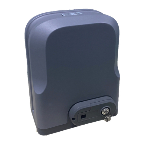
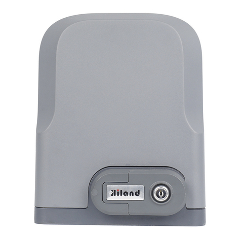
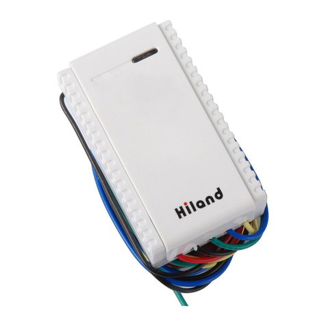
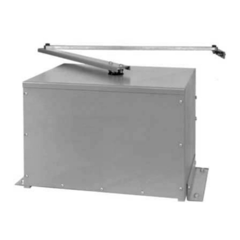
Hiland SLG5750XAC User manual

Sliding gate opener SLG5400XAC/SLG5550XAC//SLG5750XAC (SL07X0) user manual A5
Sliding Gate Opener
SLG5400XAC/SLG5550XAC/SLG5750XAC
User Manual
(With control board SL07X0)

Sliding gate opener SLG5400XAC/SLG5550XAC//SLG5750XAC (SL07X0) user manual A5
1
Dear users,
Thank you for choosing this product. Please read the manual carefully before assembling and using it.
Please do not leave out the manual if you send this product to a third party.
1. Safety Instruction
Please ensure that the using power voltage matches with the supply voltage of gate opener
(AC110V or AC220V); kids are forbidden to touch the control devices or the remote-control unit.
The remote-control unit is controlled by a single button mode or three button mode (please refer to
the instructions of the remote control in accordance with the actual gate opener type). The indicator
light on the remote-control unit will flicker when the button on it is pressed. Main engine and gate can
be unlocked by disengagement wrench and the gate can move with manual operation after
disengagement.
Please ensure that no one is around the main engine or gate when the switch is operated and it is
usually demanded to examine the stability of installation. Please temporarily stop using if the main
engine needs repairing or regulation.
The installation and maintenance of the products must be carried out by professionals.

Sliding gate opener SLG5400XAC/SLG5550XAC//SLG5750XAC (SL07X0) user manual A5
2
2. Packing List (standard)
No.
Picture
Name
Quantity
1
Main engine
1
2
Manual release key
2
3
Remote control
(Model optional)
2
4
Spring limit switch
accessories box / Magnetic
limit switch accessories box
1
4-1
or
Spring limit switch block
/ Magnetic limit switch block
1
4-2
Outer hexagon bolt M10X60
Foundation bolt M10
4
4
4-3
Spring limit switch block
mounting screw M6X10
/ Magnetic limit switch block
mounting screw M6X18
4
4-4
Nut M10
12
4-5
Flat washer Ø10
12
4-6
Spring washer Ø10
8

Sliding gate opener SLG5400XAC/SLG5550XAC//SLG5750XAC (SL07X0) user manual A5
3
No.
Picture
Name
Quantity
5
Mounting plate
1piece
Packing list (Optional)
No.
Picture
Name
Quantity
1
Metal rack
1m/pc
2
Nylon rack
1m/pc
3
0
8
5 6
97
4
1 2 3
Keypad(different
models are optional)
1pc
4
Flash lamp(different
models are optional)
1pc
5
Photocell(different models
are optional)
1pair
3. Technical parameters
Model
SLG54001
SLG54002
SLG54003
SLG54004
Power supply
110VAC/50Hz
110VAC/50Hz
220VAC/50Hz
220VAC/50Hz
Motor power
400W
400W
400W
400W
Gate moving speed
11-13m/min
11-13m/min
11-13m/min
11-13m/min
Maximum weight of
gate
1000Kg
1000Kg
1000Kg
1000Kg
Remote control
distance
≥50m
≥50m
≥50m
≥50m
Remote control
mode
Single button mode
/Three button mode
Single button mode
/Three button mode
Single button mode
/Three button mode
Single button mode
/Three button mode
Limit switch
Magnetic limit switch
Spring limit switch
Magnetic limit switch
Spring limit switch

Sliding gate opener SLG5400XAC/SLG5550XAC//SLG5750XAC (SL07X0) user manual A5
4
Noise
≤60dB
≤60dB
≤60dB
≤60dB
Output torque
22N.m
22N.m
22N.m
22N.m
Output shaft height
50mm
50mm
50mm
50mm
Frequency
433.92 MHz
433.92 MHz
433.92 MHz
433.92 MHz
Working
temperature
-20°C - +70°C
-20°C - +70°C
-20°C - +70°C
-20°C - +70°C
Package weight
16Kg
16Kg
16Kg
16Kg
Model
SLG55505
SLG55506
SLG55507
SLG55508
Power supply
110VAC/50Hz
110VAC/50Hz
220VAC/50Hz
220VAC/50Hz
Motor power
550W
550W
550W
550W
Gate moving speed
11-13m/min
11-13m/min
11-13m/min
11-13m/min
Maximum weight of
gate
1500Kg
1500Kg
1500Kg
1500Kg
Remote control
distance
≥50m
≥50m
≥50m
≥50m
Remote control
mode
Single button mode
/Three button mode
Single button mode
/Three button mode
Single button mode
/Three button mode
Single button mode
/Three button mode
Limit switch
Magnetic limit switch
Spring limit switch
Magnetic limit switch
Spring limit switch
Noise
≤60dB
≤60dB
≤60dB
≤60dB
Output torque
32N.m
32N.m
32N.m
32N.m
Output shaft height
50mm
50mm
50mm
50mm
Frequency
433.92 MHz
433.92 MHz
433.92 MHz
433.92 MHz
Working
temperature
-20°C - +70°C
-20°C - +70°C
-20°C - +70°C
-20°C - +70°C
Package weight
17Kg
17Kg
17Kg
17Kg
Model
SLG57501
SLG57502
SLG57503
SLG57504
Power supply
110VAC/50Hz
110VAC/50Hz
220VAC/50Hz
220VAC/50Hz
Motor power
750W
750W
750W
750W
Gate moving speed
11-13m/min
11-13m/min
11-13m/min
11-13m/min
Maximum weight of
gate
2000Kg
2000Kg
2000Kg
2000Kg
Remote control
distance
≥50m
≥50m
≥50m
≥50m

Sliding gate opener SLG5400XAC/SLG5550XAC//SLG5750XAC (SL07X0) user manual A5
5
Remote control
mode
Single button mode
/Three button mode
Single button mode
/Three button mode
Single button mode
/Three button mode
Single button mode
/Three button mode
Limit switch
Magnetic limit switch
Spring limit switch
Magnetic limit switch
Spring limit switch
Noise
≤60dB
≤60dB
≤60dB
≤60dB
Output torque
42N.m
42N.m
42N.m
42N.m
Output shaft height
50mm
50mm
50mm
50mm
Frequency
433.92 MHz
433.92 MHz
433.92 MHz
433.92 MHz
Working
temperature
-20°C - +70°C
-20°C - +70°C
-20°C - +70°C
-20°C - +70°C
Package weight
18Kg
18Kg
18Kg
18Kg
4. Installation
SLG5400X, SLG5550X, SLG5750X sliding gate opener is applicable to gate weight less than
1000kg/1500kg/2000kg, and length of the sliding gate should be less than 12m. The drive mode
adopts the gear and rack transmission. This gate opener must be installed inside the enclosure or
yard for protection.
4.1 Installation drawing
Figure 1
①Gate opener; ②Wireless keypad ; ③Gate; ④Infrared sensor;
⑤Alarm lamp; ⑥Safety stop block; ⑦Gear rack; ⑧Remote control;

Sliding gate opener SLG5400XAC/SLG5550XAC//SLG5750XAC (SL07X0) user manual A5
6
4.2 Size of main engine and accessories
4.2.1 Size of main engine
Figure 2
4.2.2 Size of mounting plate
270
177
150±0.3
141±0.3
4×φ10
Figure 3
4.3 Installation procedures
4.3.1 Preparation work before installation
Please ensure that the sliding gate is correctly installed, the gate rail is horizontal, and the gate can
glide back and forth smoothly when moved by hands before installing the gate opener.

Sliding gate opener SLG5400XAC/SLG5550XAC//SLG5750XAC (SL07X0) user manual A5
7
Cable installation
Please bury the motor & power cable and controlling cable with PVC tube, and use two PVC tubes
to bury (motor & power cable) and (controlling cable) separately, so as to guarantee normal
operation of the gate opener and protect the cables from damages.
Concrete pedestal
Please cast a concrete pedestal with the size of 500mm x 300mm and depth of 250mm in advance,
so as to firmly install SLG5400X, SLG5550X, SLG5750X gate opener. Please verify whether the
distance between the gate and gate opener is suitable before casting the pedestal.
Embedded screws
Figure 4
4.3.2 Main engine installation
a) Dismantle the plastic housing on the main engine before installation and keep relevant fasteners
properly;
b) Please prepare the power line for connecting mounting plate and main engine (the number of
power supply cable core shall not be less than 3 PCS, the sectional area of cable core shall not be
lower than 1.5mm²and the length shall be determined by users according to the field situation) due
to different installation environments;
c) Please unlock the main engine before installation, the unlock method is: take out the key cover,
insert the key, and open the manual release bar till it rotates by 90°as shown in Figure 5. Then turn
the output gear and the gear can be rotated easily;

Sliding gate opener SLG5400XAC/SLG5550XAC//SLG5750XAC (SL07X0) user manual A5
8
Figure 5: Turn on 90°
4.3.3 Gear rack installation
⚫Fix the mounting screws to the rack.
⚫Put the rack on the output gear, and weld the mounting screw to the gate (each screw with one
solder joints firstly).
⚫Unlock the motor and can pull the gate smoothly.
⚫Please check whether there is a fit clearance between rack and output gear, as shown in Figure
7.
⚫Weld all the mounting screws to the gate firmly.
⚫Make sure that all racks on the same straight line.
⚫Pull the gate after installed, make sure the entire trip is flexible no stuck.
Figure 6
The fit clearance of output gear and rack is shown in Figure 7 below:

Sliding gate opener SLG5400XAC/SLG5550XAC//SLG5750XAC (SL07X0) user manual A5
9
1-21-2
GearGear rackrack
OutputOutput geargear
mmmm
Figure 7
Warnings
·To ensure safety, install safety stop blocks on both ends of the rails to prevent the gate out of the rail.
Before installing the main engine, make sure that the safety stop blocks are in place and whether it
has the function of preventing the gate from moving out of the rail and out of the safety range.
·Please ensure that the main engine and its components have good mechanical properties, and the
gate can operate flexibly when moved by hands before installing the main engine.
·In this product, one control can drive one main engine only, otherwise, the control system will be
damaged.
·Earth leakage circuit breaker must be installed where the gate movement can be seen, and the
minimum mounting height is 1.5m to protect it from being touched.
·After installation, please check whether the mechanical property is good or not, whether gate
movement after manual unlocking is flexible or not, and whether the infrared sensor (optional) is
installed correctly and effectively.
4.3.4 Limit switch adjustment
Spring limit switch - The installation site of spring limit switch is shown in Figure 8:
Figure 8

Sliding gate opener SLG5400XAC/SLG5550XAC//SLG5750XAC (SL07X0) user manual A5
10
The installation of spring limit switch stop block is shown in Figure 9:
M6×10M6×10 M6×10M6×10
Figure 9
Magnetic limit switch - The installation site of magnetic limit switch is shown in Figure 10:
Figure 10
The installation of magnetic limit switch block is shown in Figure 11:
M6×18M6×18 M6×18M6×18
Left side mounting Right side mounting
Figure 11

Sliding gate opener SLG5400XAC/SLG5550XAC//SLG5750XAC (SL07X0) user manual A5
11
Note: The default setting is right side mounting. (According to actual situation, please refer to the
“Note”of section 5.1 to adjust.)
5. Control board wiring
5.1 The opener should be install on the left side of the sliding door because it is set as clockwise
when delivery. If needs to install on the right side of the sliding door, the DIP switch 3 should be
changed into the opposite side.
5.2 Disconnect the power and connect the wires by professionals
5.3 Open the top cover of the motor, and connect the wires according to the following figure (user
just connects the interfaces of AC input, flash lamp, external control switch, photocell and
24VAC output), then install the top cover again after debugging.
Figure 12

Sliding gate opener SLG5400XAC/SLG5550XAC//SLG5750XAC (SL07X0) user manual A5
12
5.4 Controller wiring instructions
5.4.1 Flash lamp interface: for connecting the flash lamp (220VAC), it only work during operation.
5.4.2 The Photocell switch interface: for connecting the infrared
protection switch (infrared switch NC contact) and 24VAC can be used as power supply. If
you do not use the infrared protection interface, then you need to make the terminal
shorted connect (Shorted in factory).
5.4.3 External control (COMMAND) interface: control switch connects normally open switch.
5.4.4 External safety edge interface (8K2): safety edge interface. If you don't need to install it, you
need to connect an 8.2KΩ resistor between the 8K2 interface and the COM (it has been connected
at the factory).
5.4.5Dip switch settings:
6. Set process
6.1Learning and erasing transmitters: Press the learning button S3 in the board, LED DL2 is on,
enters into the learning process; Press the same button twice, LED blinks for several times, then off.
The learning process is successful. Press the learning button, continue pressing for 8s until LED
turns off; Release learning button, LED will be on (about 1s) and then off; the erasing process is
successful. (Ignore this step if transmitter already matches the opener before delivery).The board
can learn 30pcs transmitters max.
Tip of Remote control self-learning function: Use the transmitter that already has been learned as
old transmitter, press button 1 and button 2 at the same time and then press button 2 to let it enters
into the learning process .In this way , new transmitter can be learned without press the learning
button on the control board.
6.2 Opening/closing limit adjustment: Remote control the door ( or move the door manually ) , adjust
the position of limit device to make sure the door would touch the limit switch when open or close the
door .LED LD6/DL5 in the controller will be off when limit device touches limit switch(Limit switch is
NC).
6.3 Resistance adjustment: Adjust potentiometer P.Open/P.Close to change the opening/closing
resistance. Resistance increases when adjust it C.W .Make a resistance to door after the adjustment
in order to check if it is appropriate.
DIP1: External limit NC/NO switch
ON:External limit NC switch
OFF:External limit NO switch
DIP2: Single/three button
ON :Single button control
OFF:Three button control
DIP5 DIP6:Auto close time
OFF OFF :No Auto close
OFF ON :5S
ON OFF :10S
ON ON :30S
DIP4:Latch and non-latch
ON: Deadman, latch
OFF: Non-latch
DIP3 Left/right installation
ON :In left side
OFF:In right side

Sliding gate opener SLG5400XAC/SLG5550XAC//SLG5750XAC (SL07X0) user manual A5
13
6.4 Motor quick running time setting: Adjust PT3 to change the quick running time(3-120S
adjustable), time increase when clockwise to adjust, time reduce when anticlockwise to adjust. Max
motor running time=quick running time +slow running time=127S. Motor quick running speed is
about 1/5M/S, slow running speed is about 1/17M/S.
6.5 External infrared switch: Photocell connector connects the NC contact of photocell switch , DL4
LED turn on after the connection, And DL4 LED turn off when blocking out the transmit or receive
signal of photocell artificially. Infrared sensor doesn't react when door opening and the door will
reverse to limit point if photocell signal disconnect when door closing. If no need of using photocell
protection, make the connector of photocell short circuit with terminated line(the connector is short
circuit when leave factory).
6.6 Safety protection function detection (if the safety protection switch is not installed, this step is
omitted): In the process of closing the door, if the safety edge protection switch is touched manually,
the sliding gate opener should stop immediately and run in the reverse direction to the door opening
limit.
7. Operational processes
7.1 Three button control process (DIP 2 at OFF position)

Sliding gate opener SLG5400XAC/SLG5550XAC//SLG5750XAC (SL07X0) user manual A5
14
7.2 Single button control process (DIP 2 at ON position)
Description:
Single button control , press-open-press-stop-press-stop; Only the learned button is effective in the
transmitter, original button is not effective any more when a new button has been learned in the same
transmitter (For example, button 1 was learned firstly, button 2 or 3 has been learned of the same
transmitter afterwards , then button 1 was not effective any more)
7.3Pedestrian Mode:The NO4 button is for Pedestrian Mode,press No4 button when the motor is in
the closing limit and not working, the motor will open and run for 10 seconds, then stop about 1.4 meters.
(soft start 1 second, quick running 6 seconds, soft stop 3 seconds).
(Pedestrian Mode is only for 4keys transmitter).
8. Maintenance
8.1 Check the door once a month to see if door is running properly.
8.2 Check reverse when meets resistance feature once a month, if not working well then must
be re-adjust.
8.3 In order to be safe, it is recommended that each door install with infrared protection
device and checked on a regular basis.

Sliding gate opener SLG5400XAC/SLG5550XAC//SLG5750XAC (SL07X0) user manual A5
15
9. Exception handling
The interpretation and ownership of this manual belong to Hiland company. Any change of the
product can be without prior notice.
Problem
Possible causes
Solutions
Door cannot open or
close, LED is not working
1. Power off
2. Fuse burned
1. turn on power
2. replace the fuse
Door only can open and cannot
close.
1. Infrared protection switch is blocked.
2.If interface is reliable shorted when
infrared switch protection switch is not i
nstalled.
3.Losing efficacy when touching the
safety edge.
4. Whether the short-circuited 8.2K ohm
resistor is not connected properly.
1. Remove the blocking.
2. shorted infrared switch interface,
the DL2 LED lamp light as normal.
3. Untouch the safety edge.
4. Reconnect the resistor.
Remote control problem
1. remote control is not learned
2. remote control battery is low (remote
control battery life 6-12 months,
depending on frequency of use)
1. learn remote control again
2. replace the remote
control batteries
Limit switch does not work
1. If door limit switch cable is opposite
2. If magnet on the door has reached t
he magnetic limit-free parts
3. dip switch in the controller and did
not make to the OFF side
1. replace limit switch connections
2. adjust the position limit magnets
3. set the dip switches to the OFF si
de
Door stops or reverse when
working
1. the door was stuck by something
2. resistance potentiometer setting too
low or changes after long time
1. remove the resistance
2. reset the resistance
potentiometer
This manual suits for next models
2
Table of contents
Other Hiland Gate Opener manuals
Popular Gate Opener manuals by other brands

Chamberlain
Chamberlain LiftMaster Professional BG770 Wiring diagram
MyGate
MyGate myHook Series Installation and use manual
Proteco
Proteco Ace TA Installation and use manual
Viper
Viper TC-3 Installation and owner's manual
Beninca
Beninca DU.35L Operating instructions and spare parts catalogue
Casit
Casit EQ2006 manual

SEA
SEA ALPHA 200 PLUS manual
tau
tau ARM2000ENC Use and maintenance manual

Merlin
Merlin Swing A 200 Installation and operating instructions
Leb Electronics
Leb Electronics TINY manual
CENTURION SYSTEMS
CENTURION SYSTEMS V400 Mechanical Installation Manual
GFA
GFA ELEKTROMAT KE 9.60 FU-25,00 installation instructions
