Hills Rotary 400 User guide

Rotary Folding Hoists
Installer’s Manual
To suit models:
Rotary 400TM
Rotary 450TM
Rotary 500TM


Contents
Page
Item 1: Replacing the Upper Cross Cover 4
Item 2: Repairing the Upper Cross Assembly 4
Item 3: Replacing the Locking Collar 5
Item 4: Repairing the Lower Cross Assembly 6
Item 5: Repairing the Latch Assembly 8
Item 6: Repairing the Handle Assembly 9
Item 7: Replacing an Arm Assembly 10
Item 8: Repairing a Tensioner Assembly 11
Item 9: Restringing a Line Segment 11
Item 10: Restringing the Hoist 12
Item 11: Replacing the Ground Socket Locking Collar 12
Item 12: Replacing the Windbrake and Winding Mechanism 13
Line Length Chart 14

4
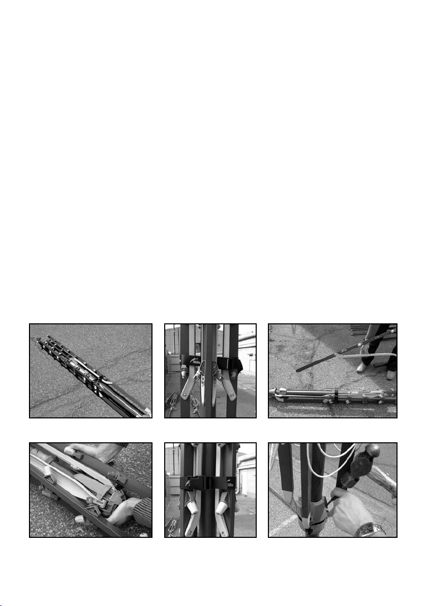
Item 1: Replacing the Upper Cross Cover
1. Fold up the hoist and secure with the Line Tie-Off Strap (Fig. 1).
2. Remove hoist from the Ground Socket and lay it on the ground.
3. Using a screwdriver, gently lever up one on the bottom flaps to disengage
the central snap (Fig. 2).
4. To replace, snap on the new cover (Fig. 3).
Fig. 1 Fig. 2 Fig. 3
Item 2: Repairing the Upper Cross Assembly
You will require the Upper Cross disassembly tool set (red) for this operation.
1. Open the hoist whilst in the Ground Socket.
2. Place disassembly tool into one of the recessed grooves of the Cross Assembly (Fig. 4)
3. Push the tool upwards towards the stay until it locates.
4. Use an 8mm Allen key to turn the central cam through 90 degrees. This action spreads
the locating snap features away from their locking ledge (Fig. 5)
5. Repeat this with the remaining three tools around the cross.
6. Fold up the hoist and attach the line tie-off strap, remove from the Ground Socket.
7. Remove the Upper Cross Cover as described in Item 1.
8. Remove the screw from the top of the hoist (Fig. 6)
9. Using a screwdriver, gently lever the Upper Cross halves apart to separate (Fig. 7)
10. Once the Upper Cross is separated the Arm Stays can be accessed if they need
to be serviced.
11. To remove the Upper Cross Bottom undo the two screws holding it to Secondary
Standard (Fig. 8)

5
12. To re-assemble the Upper Cross Assembly re-attach the Upper Cross Bottom to the
Secondary Standard using the two screws.
13. Place all of the Arm Stays into the pivot recesses in the Upper Cross Bottom.
14. Unlock and remove the disassembly tools from the four recesses around the cross.
15. Locate and push the Upper Cross Top into the Upper Cross Bottom until the locating
snaps have re-engaged (Fig. 9). Note: check all Arm Stay Pivots are engaged correctly.
16. Replace the screw into the top of the assembly.
17. Snap the Upper Cross Cover back on.
Fig. 4 Fig. 5 Fig. 6
Fig. 7 Fig. 8 Fig. 9
Item 3: Replacing the Locking Collar
To service the Locking Collar you must first remove the Upper
Cross Assembly as described in Item 2.
1. Remove the screw from the Locking Collar and slide it
off the top of the Secondary Standard. (Fig. 10)
2. To re-assemble, slide on a new Locking Collar
and re-secure.
3. Re-assemble the Upper Cross Assembly. Fig. 10
90º

6
Item 4: Repairing the Lower Cross Assembly
You will require the Lower Cross disassembly tool set (blue) for this operation.
1. Fold up the hoist and secure with the line-tie off strap (See Fig. 1).
2. Place the disassembly tool into one of the recessed grooves of the Lower
Cross assembly.
Note: Steps 2 to 5 are similar to steps 2 to 5 in item 2, Repairing the Upper
Cross Assembly
3. Push the tool upwards towards the Arm Joiner until it locates.
4. Use an 8mm Allen key to turn the central cam through 90 degrees. This action spreads
the locating snap features away from their locking ledge (See Fig. 5)
5. Repeat this with the remaining three tools around the cross.
6. Remove the hoist from the Ground Socket and lay it down with the
Main Standard supported.
7. Using a screwdriver, gently lever the cross halves apart to separate the cross (Fig. 11).
8. Once the cross is separated the Arm and Latch assemblies can be accessed.
9. To replace the Lower Cross Assembly you will need to remove the Handle assembly (Item
6) and also the Locking Pin and Locking Collar (Item 11) from the main standard.
10. Once these items are out of the way the halves can be slid off the bottom of the hoist.
(Fig. 12 and 13)
11. After the Lower Cross Assembly has been serviced or replaced re-assemble the
components that were removed in points 8, 9 and 10 (Fig. 14).
12. Place the hoist back into the Ground Socket.
13. Align the top of the Lower Cross Assembly and Latch with the screw in the Locking Collar
to ensure correct hoist operation (Fig. 15).
14. Locate and secure the Arm Joiners by locating them into the pivot recesses in the Lower
Cross Top.
15. Unlock and remove the disassembly tools from the four recesses around the cross.
16. Push the two halves of the cross together to line up the 8 snap hooks (Fig 16).
17. Using the Pin Punch provided and a hammer knock the two halves of the cross assembly
together (Fig. 17).
18. Ensure all 8 hooks have engaged and the Arm Joiners are seated correctly before opening
the hoist.

7
Fig. 11 Fig. 12 Fig. 13
Fig. 14 Fig. 15
Fig. 16 Fig. 17

8
Item 5: Repairing the Latch Assembly
1. Disassemble the Lower Cross Assembly as described in Item 4, Steps 1 to 8 (Fig. 18).
2. Lever the Latch assembly off the retaining ledge (Fig. 19).
3. Service the Latch Assembly (Fig. 20).
4. Ensure when Locking Fork is replaced with the Sliding Latch, the lower snap detail
is facing towards the Main Standard (Fig. 21).
5. Slide the assembly into the locating slot until it has re-engaged the snap
detail (Fig. 22 and 23).
6. Re-assemble the Lower Cross Assembly (Fig. 23). Refer to Item 4, Steps 16, 17 and 18.
Fig. 18 Fig. 19 Fig. 20
Fig. 21 Fig. 22 Fig. 23

9
Item 6: Repairing the Handle Assembly
1. To remove the Handle Assembly, the Shroud Plug and Badge need to be removed.
2. The Badge will disengage from the Handle Assembly by gently levering using a small
screwdriver (Fig. 24).
3. Remove the Shroud Plug by punching a hole in the centre, then lever out the retaining
snaps. This prevents damaging the Handle Shroud (Fig. 25).
4. Remove the two screws and pull the Handle Assembly away from the standard
(Fig. 26 and 27).
5. Ensure the Handle Spring does not fall out of the Handle Assembly when removing
the assembly. (Fig. 28).
6. To replace the Handle use a pair of pliers to disengage the snaps at the back of the
Handle Shroud (Fig. 29).
7. To reassemble the Handle snap it back into the Handle Bush with the Handle Shroud
and Spacer Ring in between (Fig. 30).
8. Re-attach the assembly to the standard with the two fasteners, replace the Badge and
snap in a New Shroud Plug (Fig. 31 and 32).
Fig. 24 Fig. 25 Fig. 26
Fig. 27 Fig. 28 Fig. 29
Fig. 30 Fig. 31 Fig. 32
10
Item 7: Replacing an Arm Assembly
1. Remove all of the line segments from the hoist to prevent tangling (Fig. 33).
2. Lock into place the 8 disassembly tools in both the Upper and Lower Crosses (as per item
2 and 4). Do not lever the crosses apart.
3. Fold up the hoist and attach the line tie-off, only securing the arm assemblies that are not
being replaced (Fig. 34).
4. Place the hoist on the ground.
5. Disassemble the Upper Cross Assembly as per Item 2.
6. Disassemble the Lower Cross Assembly as per Item 4.
7. Remove the damaged Arm Assembly from the cross assemblies (Fig. 35).
8. Place the Arm Stay Pivot of the new assembly into the Upper Cross, ensuring the others
have not fallen out.
9. Re-assemble the Upper Cross (Fig. 36) as per Item 2, Steps 13 to 17.
10. Re-attach the Line Tie-Off strap to include all 4 arms (Fig. 37).
11. Replace the hoist in the Ground Socket.
12. Place the Arm Joiners into the pivots of the Lower Cross bottom.
13. Re-assemble Lower Cross (Fig. 38) as per Item 4, Steps 14 to 18.
14. Re-attach the lines.
Fig. 33 Fig. 34 Fig. 35
Fig. 36 Fig. 37 Fig. 38

11
Item 8: Repairing a Tensioner Assembly
1. Remove the Line Segments and Cover Caps that are attached to both sides of the
Tensioner Assembly (Fig. 39).
2. Flex the Tensioner assembly upwards. This will allow the snaps to disengage so the
tensioners can be removed (Fig. 40).
3. To replace the tensioners, locate them into the corresponding holes in the arms with the
word “TOP” facing upwards. If the tensioners do not assemble by hand, use a pair of
large multi-grips (Fig. 41). Note: ensure they are assembled in the correct orientation.
4. Once the tensioners are assembled to the arm, the line and caps can be reattached.
Fig. 39 Fig. 40 Fig. 41
Item 9: Restringing a Line Segment
1. Establish the line segment that needs replacing and refer to the Line Length Chart for
correct line length (see Page 14).
2. Attach and tension the lines as per following sequence of diagrams.
Step 1
Remove the line cover by rotating
anti-clockwise.
Step 4
Feed the line up and through the
front slot of the tensioner and
pull tight.
Step 2
After unthreading the line from
the tensioner, pull the line through
tensioner until desired tension is
reached. Do not overtension.
Step 5
Using scissors carefully trim off
excess line, leaving approximately
10mm sticking out.
Step 3
Loop line around the rear groove
of the tensioner and pull tight to
prevent line from slipping.
Step 6
Re-attach line cover by rotating
clockwise. This will obscure
the small piece of excess
line remaining.
10mm
12
Item 10: Restringing the Hoist
1. Cut the line sections for the complete hoist as per the Line Length Chart (see page 14).
2. Initially only restring the 4 outside line segments.
3. Attach the four outside line segments to each of the four outside tensioners, tension
the line. Note: ensure Cover Caps are threaded onto each line before tensioning and
fastening.
4. Look down each arm to ensure the squareness of the hoist.
5. Attach the remaining line segments.
6. Review all lines and check to determine if any segments require re-tensioning.
7. Fold the hoist up and down to ensure hoist is not over tensioned and restricting the
engagement of the Lower Cross and Latch with the Locking Collar.
8. Once complete, trim off excess line leaving about 10mm protruding from each tensioner.
Fit Cover Caps.
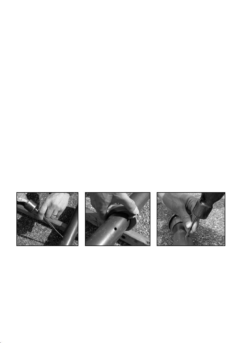
Item 11: Replacing the Ground Socket Locking Collar
1. Remove the Locking Pin from the bottom of Main Standard, use the
Pin Punch provided (Fig. 42).
2. Remove damaged part (Fig. 43).
3. Install a new part and replace the Locking Pin (Fig. 44).
Fig. 42 Fig. 43 Fig. 44

13
Item 12: Replacing the Windbrake and Winding Mechanism
1. Remove the hoist from the Ground Socket and lay it on the ground.
2. Remove the Handle Assembly as per Item 6.
3. Remove the screw in the Main Standard located behind the Handle Assembly. This screw
secures the Winding Mechanism within the Main Standard (Fig. 45).
4. Using a screwdriver and hammer, remove the Windbrake from the top of the Main
Standard (Fig. 46).
5. Carefully slide the Main Standard completely off the Secondary Standard, ensure that the
Winding Mechanism does not become dirty, and the Ground Socket Locking Collar does
not fall off. If the saddle or pinion gear become dislodged, clean and lubricate them with
Vaseline before replacing (Fig. 48).
6. Use a hacksaw to cut the bard off the top of the Worm (Fig. 47).
7. Fit a new Winding Mechanism into the Main Standard and secure with the screw (Fig. 49).
8. Push a new or the removed Windbrake into the top of the Main Standard, ensuring that
the moulding is aligned with the punched details in tube. Centre punch the tube in the
nibbed areas to re-secure (Fig. 50).
9. Slide the Main Standard over the Secondary Standard then stand hoist upright in the
Ground Socket to re-engage the worm with the Secondary Standard.
10. Re-attach the handle assembly as per Item 6.
Fig. 45 Fig. 46 Fig. 47
Fig. 48 Fig. 49 Fig. 50

14
Line Length Chart
This chart shows the length of line to cut for each section. It gives the required length plus
200mm to allow easy installation
Hills Rotary 400TM
970
mm 1
197
mm
Hills Rotary 450TMHills Rotary 500TM
2827mm
2580mm
2333mm
2086mm
1832mm
1578mm
1329mm
970mm
2580mm
2333mm
2086mm
1832mm
1578mm
1329mm
970mm
2086mm
1832mm
1578mm
1329mm

15
Notes
Issue – November 2007

This manual suits for next models
2
Table of contents
Other Hills Household Appliance manuals

Hills
Hills Hoist 8-Line User manual

Hills
Hills Supa Fold 230 User manual

Hills
Hills Supa Fold Post Kit Standard - Adjustable... User manual

Hills
Hills FD52007 User manual

Hills
Hills Premium Supa Fold Long Line User manual

Hills
Hills Everyday Rotary 37 User manual

Hills
Hills Supa Fold 230 User manual

Hills
Hills Portable 120 User manual

Hills
Hills HILLS HERITAGE 5 User manual

Hills
Hills Traditional Rotary 42 Hoist User manual


