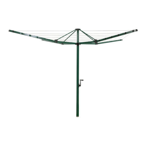
Hills Supa Fold Post Kit Standard - Adjustable... User manual

Supa® Fold
Post Kits
Owner’s Manual
TO SUIT POST KIT MODELS:
Supa® Fold Post Kit Standard - Adjustable
Supa® Fold Post Kit Long - Adjustable
Supa® Fold Post Kit Standard - Fixed
Supa® Fold Post Kit Long - Fixed
TO SUIT POST KIT MODELS:
Supa
®
Fold Post Kit Standard - Adjustable
Supa
®
Fold Post Kit Long - Adjustable
Supa
®
Fold Post Kit Standard - Fixed
Supa
®
Fold Post Kit Long - Fixed

Congratulations
Congratulations on the purchase of
your new Hills Supa® Fold Folding Frame
Post Kit.
It is important that you read this Owner’s
Manual thoroughly before installation and
use. In this way you will benefit from all the
design features and enjoy safe use of the
product.
Thank you for choosing Hills.
Warning
• Do not allow children or pets to swing on
your Clothesline or items of laundry.
• Ensure when raising and lowering your
Clothesline that bystanders (in particular
children) are standing well clear.
• Do not use your Folding Frame
Clothesline for any purpose other than
to hang and dry washing.
• Do not use your Clothesline if parts are
worn or damaged.
• Patents and Registered Designs apply
to this product.
• Do not allow the frame to lower in an
uncontrolled manner as damage or injury
may result.
For any assistance in Australia call
Hills Consumer Advice
on 1300 300 564 (cost of a local call)
during normal business hours
or visit www.hills.com.au
For any assistance in New Zealand call
09 262 3052 during normal business hours.
Consumer Advice
Please retain this Owner’s Manual. Record
the following information from the carton for
future reference.
Product Number: FD
Date of purchase:
Name and location of store:
Introduction

1
Supa® Fold Post Kit Standard - Fixed
Part name Qty.
Post - Fixed 2
Cross Brace 1
Owner’s Manual 1
Post Kit Accessory Bag (includes): 1
M8 x 75 ZP socket head screw 2
M8 x 60 ZP socket head screw 2
M8 ZP nyloc nuts 4
M8 ZP washers 8
Unpacking the Supa® Fold
Folding Frame Post Kit
1. Open the front face of the carton
(all carton materials can be recycled).
2. Check all components are in the carton
(refer to tables below for your model).
Pack Contents
Supa® Fold Post Kit Long - Fixed
Part name Qty.
Post - Fixed 2
Cross Brace 2
Cross Brace Joiner 1
Owner’s Manual 1
Post Kit Long Accessory Bag (includes): 1
M8 x 75 ZP socket head screw 2
M8 x 60 ZP socket head screw 2
M6 x 16 ZP socket head screw 2
M6 ZP washer 2
M8 ZP nyloc nuts 4
M8 ZP washers 8
4mm Hex Key 1
Supa® Fold 190 Post Kit - Adjustable
Part name Qty.
Post - Adjustable 2
Cross Brace 2
Cross Brace Joiner 1
Owner’s Manual 1
Post Kit Accessory Bag (includes): 1
M8 x 75 ZP socket head screw 2
M8 x 60 ZP socket head screw 2
M6 x 16 ZP socket head screw 2
M6 ZP washer 2
M8 ZP nyloc nuts 4
M8 ZP washers 8
4mm Hex Key 1
Supa® Fold Post Kit Standard -
Part name Qty.
Post - Adjustable 2
Cross Brace 1
Owner’s Manual 1
Post Kit Accessory Bag (includes): 1
M8 x 75 ZP socket head screw 2
M8 x 60 ZP socket head screw 2
M8 ZP nyloc nuts 4
M8 ZP washers 8
Supa® Fold Post Kit Standard - Adjustable
Supa® Fold Post Kit Long - Adjustable

2
0.5m
1m
0.5m
Depth
Width
Ensure area is
free from obstructions
Select a suitable location
1. Select a suitable location for your Post
mounted Supa® Fold Clothesline.
2. Ensure you have left sufficient space
surrounding the Clothesline (Fig. 1).
We recommend 0.5m each side and
1m in front.
Fig. 1
Installation
Product Dimensions
Product Width
(mm)
Depth
(mm)
Supa® Fold 230 Advantage 2270 1500
Supa® Fold 230 2270 1500
Supa® Fold 210 2270 1500
Supa® Fold 190 3420 780
Supa® Fold 120 2270 780
1. Assemble Cross Brace
The Cross Brace is pre-assembled in
these models;
• Supa® Fold Post Kit Standard - Fixed
• Supa® Fold Post Kit Standard - Adjustable
The Cross Brace requires assembly in
these models;
• Supa® Fold Post Kit Long - Fixed
• Supa® Fold Post Kit Long - Adjustable
A. Assemble the Cross Braces using the Cross
Brace Joiner, M6 x 16.0 low profile socket
bolt and M6 washers (Fig. 2).
B. Tighten both bolts using the 4mm Hex Key
supplied (Fig. 3).
Fig. 2
Fig. 3
Cross
Brace
M6 x 16.0
Cross
Brace
4mm Hex Key
Cross Brace
M6 Washer
M6 Washer

3
Installation
Installing the Post Kit ‘Post Hole Centres’
Product Centres
(mm)
Supa® Fold 230 Advantage 2200
Supa® Fold 230 2200
Supa® Fold 210 2200
Supa® Fold 190 3350
Supa® Fold 120 2200
Recommended Installation Height
You will require the following materials
and tools:
Pre-Mix Concrete
Coarse Gravel
Spade
Tape Measure
Spirit Level
30mm
Ground Level
50mm
User’s Head Height
Refer to specific installation page for details.
• User’s Head Height = Top of Bracket
• Recommended Clearance = User’s Head Height + 50mm
• Post Height = User’s Head Height + 30mm
Top of Bracket

4
Installation
A. Having selected a suitable location,
dig two holes approximately 200mm
diameter x 600mm deep at hole
centres to suit your product (see Post
Hole Centre Chart on pg. 5). Place
approximately 150mm of coarse gravel
into the hole.
B. Place Posts into the hole. Push the base
of the Posts into the gravel until the
recommended height is achieved. We
recommend that the Spreader Bar of
your Supa® Fold is installed 50mm above
your typical user head height, therefore
the top of the Posts must be installed
30mm above user head height (refer to
diagram pg. 5).
C. Loosely fasten the Cross Brace to the top
hole in each Post using the M8 x 75mm
socket head bolts.
D. Support and check (using a spirit level
and tape measure) that the Posts are
parallel with each other and level, both
vertically and horizontally.
E. Concrete Posts into position. Concrete
should be damp enough to hold together
when squeezed in your hand. Pack the
concrete firmly and settle by poking with
a thin stick. Slope the top surface of the
concrete away from the Posts to provide
drainage away from the Post.
F. Re-check Posts are parallel and level,
then allow concrete to set thoroughly
for at least 24 hours before final product
assembly.
Installing Fixed Posts directly
into the ground
Post - Fixed
200mm
450mm
Concrete
150mm
Gravel
600mm
Slope top
surface of
concrete away
from post.

5
Installation
A. Having selected a suitable location,
dig two holes approximately 200mm
diameter x 600mm deep at hole
centres to suit your product (see Post
Hole Centre Chart on pg. 5). Place
approximately 150mm of coarse gravel
into the hole.
B. Place Posts in sleeves into the holes.
Push the base of the sleeves into
the gravel until they sit approximately
5-10mm above ground level. We
recommend that the Spreader Bar of
your Supa® Fold is installed 50mm above
your typical user head height, therefore
the top of the Posts must be installed
30mm above user head height (refer to
diagram pg. 5).
C. Loosely fasten the Cross Brace to the top
hole in each Post using the M8 x 75mm
socket head bolts.
D. Support and check (using a spirit level
and tape measure) that the Posts are
parallel with each other and level, both
vertically and horizontally.
E. Concrete Posts into position. Concrete
should be damp enough to hold together
when squeezed in your hand. Pack the
concrete firmly and settle by poking with
a thin stick. Slope the top surface of the
concrete away from the Posts to provide
drainage away from the Post.
F. Re-check Posts are parallel and level,
then allow concrete to set thoroughly
for at least 24 hours before final product
assembly.
Installing Fixed Posts using
Ground Sleeves
Your Posts can be installed using Ground
Sleeves, which allow future removal of
the Posts if required. Ground Sleeves are
available from Hills as optional accessories.
Sleeve
Post - Fixed
200mm
450mm
Concrete
150mm
Gravel
600mm
Slope top
surface of
concrete away
from post.
5-10mm

6
Installation
A. Having selected a suitable location,
dig two holes approximately 200mm
diameter x 600mm deep at hole
centres to suit your product (see Post
Hole Centre Chart on pg. 5). Place
approximately 150mm of coarse gravel
into the hole.
B. Your Adjustable Posts provide 200mm of
height adjustment in 50mm increments.
We recommend these are pre-set to the
middle position prior to fixing in concrete
(Refer to Fig. 4, pg. 10) This will provide
adjustment in either direction for future
height adjustment.
C. Place the Posts into the holes. Push the
base of the Posts into the gravel until the
recommended height is achieved. We
recommend that the Spreader Bar of
your Supa® Fold is installed 50mm above
typical user head height, therefore the
top of the Posts must be installed 30mm
above user head height (refer to diagram
pg. 5).
D. Loosely fasten the Cross Brace to the top
hole in each Post using the M8 x 75mm
socket head bolts.
E. Support and check (using spirit level and
tape measure) that the Posts are parallel
with each other and level, both vertically
and horizontally.
F. Concrete Posts into position. Concrete
should be damp enough to hold together
when squeezed in your hand. Pack the
concrete firmly and settle by poking with
a thin stick. Slope the top surface of the
concrete away from the Posts to provide
drainage away from the Post.
G. Re-check Posts are parallel and level,
then allow concrete to set thoroughly
for at least 24 hours before final product
assembly.
Installing Adjustable Posts
Directly into the ground
Post - Adjustable
200mm
450mm
Concrete
150mm
Gravel
600mm
Slope top
surface of
concrete away
from Post

7
Installation
A. Having selected a suitable location,
dig two holes approximately 200mm
diameter x 600mm deep at hole
centres to suit your product (see Post
Hole Centre Chart on pg. 5). Place
approximately 150mm of coarse gravel
into the hole.
B. Your Adjustable Posts provide 200mm of
height adjustment in 50mm increments.
We recommend these are pre-set to the
middle position prior to fixing in concrete
(refer to Fig 4, pg. 10). This will provide
adjustment in either direction for future
height adjustment.
C. Place Posts in sockets into the holes.
Push the base of the sockets into the
gravel until they sit it approximately
5-10mm above ground level. We
recommend that the Spreader Bar of
your Supa® Fold is installed 50mm above
your typical user head height, therefore
the top of the Posts must be installed
30mm above user head height (refer to
diagram pg. 5).
D. Loosely fasten the Cross Brace to the top
hole in each Post using the M8 x 75mm
socket head bolts.
E. Support and check (using a spirit level
and tape measure) that the Posts are
parallel with each other and level, both
vertically and horizontally.
F. Concrete Posts into position. Concrete
should be damp enough to hold together
when squeezed in your hand. Pack the
concrete firmly and settle by poking with
a thin stick. Slope the top surface of the
concrete away from the Posts to provide
drainage away from the Post.
Installing Adjustable Posts
using Ground Sockets
Your Posts can be installed using Ground
Sockets, which allow future removal of
the Posts if required. Ground Sockets are
available from Hills as optional accessories.
G. Allow concrete to set thoroughly for
at least 24 hours before final product
assembly.
Ground
Socket
Post - Adjustable
200mm
450mm
Concrete
150mm
Gravel
600mm
Slope top
surface of
concrete away
from post.
5-10mm

8
Fig. 4
• Your Adjustable Post Kit has five height
settings (Fig.4)
• To adjust, depress the Locking Button
and slide the upper Post up or down
(Fig.5)
• The spring loaded Locking Button will
re-engage at the next height location.
• If you are adjusting the height with the
Supa® Fold already assembled we
strongly recommend that two people
adjust the Posts simultaneously or
damage, twisting or distortion may occur.
Operating your Adjustable
Post Kit
Operation
Fig. 5
We recommend your Posts are set to the
middle setting when concreting into the
ground.
Depress button
Slide upper Post
up or down
A
B

9
Hills Guarantee
Hills Industries Limited undertakes that if
any part of its manufacture has failed to
operate correctly due to faulty workmanship
or defective material, it will repair or replace
the part free of cost for a period of TEN (10)
years from date of purchase of the article,
given fair wear and tear. Evidence of unfair
usage or incorrect adjustment by the owner
will void this promise.
Hills Industries Limited will not be
responsible for any costs in connection
with freight or Postage, or for expenditure
necessary to dismantle the article, replace
the part in position and re-assemble the
article.
This guarantee is in addition to any rights
or remedies conferred on the consumer by
Trades Practices Act or state laws.
As a proudly Australian company we
are committed to provide you complete
customer satisfaction. If you have questions
about this product or find there are missing
or damaged parts please call Hills direct
on 1300 300 819 (cost of a local call) for
assistance during normal business hours.
Hills Industries Limited do not recommend
the application of a ‘canopy’ on any of their
outdoor clothesline range.
Unless any addition or attachment to this
product has Hills specific approval or is
sold as a Hills product the warranty on this
product is waived. The product is designed
to perform a specific task under established
test loads and unauthorised attachments
may produce stresses for which the design
is not appropriate.
Designs, specifications and colours are
subject to change without notice.
Hills Industries Limited
A.B.N. 35 007 573 417
Issue June 2007
PD1229b
Guarantee
For any assistance in Australia call
Hills Consumer Advice
on 1300 300 564 (cost of a local call)
during normal business hours
or visit www.hills.com.au
For any assistance in New Zealand call
09 262 3052 during normal business hours.
Made in China

Hills Industries Limited
A.B.N. 35 007 573 417
This manual suits for next models
8
Table of contents
Other Hills Household Appliance manuals
Hills
Hills Premium Supa Fold Long Line User manual

Hills
Hills Portable 120 User manual

Hills
Hills Premium Rotary 6 User manual
Hills
Hills Traditional Rotary 42 Hoist User manual

Hills
Hills Portable 120 User manual

Hills
Hills FD52007 User manual
Hills
Hills Supa Fold 230 User manual
Hills
Hills Rotary 400 User guide

Hills
Hills Supa Fold 230 User manual
Hills
Hills HILLS HERITAGE 5 User manual
