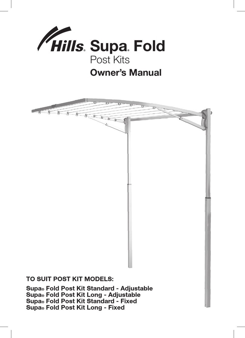
Hills FD52007 User manual

the
retracting
clothesline
product
manual 5-line

32
Congratulations
Congratulations on the purchase of your new
Hills Retracting Clothesline which will bring
you many years of trouble free and efficient
outdoor drying.
It’s important that you read this Product Manual
thoroughly before installation to benefit from
the design features and enjoy safe use of this
product.
Thank you for choosing Hills.
Warning
• Do not allow children or pets to swing on the
Clothesline or items of laundry.
• Do not use for any purpose other than to
hang and dry washing.
• Do not use your Clothesline if parts are worn
or damaged.
• Do not operate the locking lever when the
arm is located in the cabinet.
• Do not release the locking mechanism when
there are clothes attached to the lines.
• Do not allow the arm and lines to retract
uncontrolled as this may lead to personal
injury or property damage. Hold the arm
securely and walk it back to the cabinet.
Patents and Registered Designs apply to
this product.
Please retain this Product Manual. Record the following
information for future reference.
Product Number (printed on carton):
Date of purchase:
Name and location of store:
Introduction
Made in China
Designed and tested under a
Quality System that meets Hills’
demanding quality specifications.
®
Carton contents
Part name Qty.
Retracting line cabinet 1
Receiving bracket 1
Optional Post Mounting Kits
If you choose to mount your Retracting
Clothesline cabinet or receiving bracket on
posts, the following products are available.
Post Kits:
100550 – Hills Retracting Clothesline Post Kit
Mount Bar Kits:
100548 – Hills Retracting Clothesline Mount Bar
Mounting Options
Mounting Options
Determine which of the four mounting options most suits your requirements.
Wall to Wall
Wall to Post
Requires:
1 Post Kit
Post to Wall
Requires:
1 Post Kit
1 Mount Bar Kit
Post to Post
Requires:
2 Post Kits
1 Mount Bar Kit
Volume 1426795 (mm³)
MID MARKET RETRACTING LINE
D434
2010
Revision 4 - 09.02.10 - DHN
6
D
C
B
A
E
F
G
H
E
A
B
C
D
F
54321 211101987
87654321
G
019
SCALE:1:5
A2
2111
H
Project:
X. Xxxxxxxx
DO NOT SCALE DRAWING.
Projection.
:etaD:devorppA
Date:XX.XX.XX
Drawing Number
1
Estimated Mass:
Checked:
XX.XX.XXX. Xxxxxxxx Date:
Drawn:
Issued / Received Issue:
Sheet 1 of 1
TM
Colour:
Material:
Finish:
Project Number
Sheet
DIMENSIONS IN MILLIMETRES.
Third Angle
size
FD52007
RETRACTING - 5 LINE
REFER TO INDIVIDUAL COMPONENTS
2450 (grams)
REFER TO DRAWING SPECIFICATION
REFER TO COLOUR TABLE
Description
Hills Industries Limited
ABN 35 007 573 417
Home & Hardware Products
Unit H, 5 Butler Boulevard
Burbridge Business Park
Adelaide Airport
South Australia 5950
Copyright©
Additives:
Note: Minimum operating distance is 2.0m (6'6").
Maximum operating distance is 6.5m (21'4").

54 Site Selection Installation Height
Step 1 – Select a suitable location
1.1 Select a suitable location for either wall or post mounted installations.
1.2 This product has been designed to mount and operate between 2.0m (6'6") and
6.5m (21'4").
1.3 Always leave approximately 1.5m (5') clearance each side of the line and any wall
fence/shed etc.
Note: This product must only be installed on sound structural walls. May not be
suitable for mounting on timber or cladded dwelling unless the cabinet or receiving
bracket is mounted directly to vertical studs – NOT TO CLADDING.
Do not mount directly onto cladding materials.
If you have any doubt, contact your local hardware store or installer.
1.5m (5') clearance from
obstructions either side
Receiving bracket
Cabinet
Mounting surface
Arm
Mounting surface
2.0m (6'6") minimum to 6.5m
(21'4") maximum
Volume 1426795 (mm³)
MID MARKET RETRACTING LINE
D434
2010
Revision 4 - 09.02.10 - DHN
6
D
C
B
A
E
F
G
H
E
A
B
C
D
F
54321 211101987
87654321
G
019
SCALE:1:5
A2
2111
H
Project:
X. Xxxxxxxx
DO NOT SCALE DRAWING.
Projection.
:etaD:devorppA
Date:XX.XX.XX
Drawing Number
1
Estimated Mass:
Checked:
XX.XX.XXX. Xxxxxxxx Date:
Drawn:
Issued / Received Issue:
Sheet 1 of 1
TM
Colour:
Material:
Finish:
Project Number
Sheet
DIMENSIONS IN MILLIMETRES.
Third Angle
size
FD52007
RETRACTING - 5 LINE
REFER TO INDIVIDUAL COMPONENTS
2450 (grams)
REFER TO DRAWING SPECIFICATION
REFER TO COLOUR TABLE
Description
Hills Industries Limited
ABN 35 007 573 417
Home & Hardware Products
Unit H, 5 Butler Boulevard
Burbridge Business Park
Adelaide Airport
South Australia 5950
Copyright©
Additives:
Cabinet
fasteners
Cabinet
fasteners
User’s
head height
50mm (2")
User’s
head height
50mm (2")
60mm
(2¼")
115mm
(4½")
125mm
(5")
Receiving
bracket
fasteners
Receiving
bracket
fasteners
Note: The receiving bracket should
be located at a height to ensure the
clothesline is close to horizontal.
Location of receiving
bracket fasteners are
approximately 25mm (1")
above user's head height
(when installed on level
ground).
For post mounting a
receiving bracket, the
top of the post should be
approximately 125mm
(5") above user's head
height (when installed on
level ground).
Location of cabinet
fasteners are
approximately 60mm
(2¼") above user's
head height.
For post mounting
a cabinet, the top of
the post should be
approximately 115mm
(4½") above user's
head height.
Mount bar
Top of post Top of post
Post kit
Note: The receiving bracket should be located at a
height to ensure the clothesline is close to horizontal.
Wall Installation
Step 2 – Recommended installation height
2.1 For all installations, we recommend the operational height for the line is approximately 50mm
(2") above the user’s head height.
2.2 For the heights and combinations of wall/post installations refer to the appropriate details
below.
Post Installation
Cabinet
Cabinet
Receiving bracket
Receiving bracket
Post kit

76 Installation Installation
Drill 2 holes using
masonry drill
Product centre line
30mm
Mount hole centres
Top of
product
Product centre line
Step 3 – Mounting your cabinet to a wall
3.1 Prepare your cabinet location
Determine the best location for the installation of your product (refer to page 4).
Mark out a centre line for your product within your allocated site.
3.2 Ensure that either side of this centre line and the area where the cabinet is to be installed on
the wall is free from pipes and other obstructions (Fig. 1).
3.3 Mark the cabinet mount centres on the wall at the desired installation height (refer to page 5
and the table below).
Centres
(mm) Centres
(inch)
705 27¾
Fig. 1
3.4 Drill holes in wall
Masonry fasteners are not included with this product. When attaching to a sound masonry
wall, we recommend using masonry sleeve (hex head) anchors (diameter 8mm x 45mm).
3.5 If you are using these fasteners, drill an 8mm (5/16") hole using a masonry drill (Fig 2).
Note: If you are mounting to a different wall type, consult your hardware store for advice on
the appropriate fasteners to use.
Fig. 2
Mount
centres
Ensure surrounding
area is free from
obstructions
‘Mount Hole Centres’
2.0m (6'6") to
6.5m (21’4")
Step 3 (continued) – Mounting your cabinet to a wall
3.6 Remove the arm from the cabinet by pulling on the two blue end caps. Remove the end
covers only from the cabinet by unscrewing the two screws (Fig 3).
3.7 Locate the cabinet on the wall, ensure cabinet is level. Using appropriate wall fasteners
secure cabinet to the wall.
3.8 Reattach the cabinet end covers and secure with the screws. Refit arm into cabinet.
Fig. 3
Masonry anchor
(Not included)
Masonry anchor
(Not included)
End cover
End cover screw
Arm
End cover screw
Blue end cap

98 Installation Installation
Step 4 – Mounting your cabinet to a post
4.1 Prepare your cabinet location
Determine the best location for the installation of your product (refer to page 4).
Mark out a centre line for your product within your allocated site.
4.2 Determine your post locations.
Install as per the instructions supplied with your post kit.
Refer to diagram on page 5 to determine the installation height.
Refer to page 2 for the post kit available.
4.3 To post mount your cabinet you will need to purchase a matching
mount bar kit (refer to page 2).
4.4 Attach the mount bar to the post as per instructions supplied with your
mount bar kit.
Fig. 4
Ensure surrounding area
is free from obstruction
Product centre line
2.0m (6'6") to
6.5m (21’4")
Step 4 (continued) – Mounting your cabinet to a post
4.5 Remove the arm from the cabinet by pulling on the two blue end caps. Remove the
end covers only from the cabinet by unscrewing the two screws (Fig 5).
4.6 Locate the cabinet with the pre drilled holes in the mount bar (sold separately). Using
the fasteners and instructions provided with the mount bar kit secure the cabinet to
the post assembly (Fig 5).
4.7 Reattach the cabinet end covers and secure with the screws. Refit arm into cabinet.
Fig. 5
Post kit
(sold separately)
End cover
End cover
Washer
Washer
M8 nyloc nut
M8 x 45
socket head
bolt
Mount bar
(sold separately)
End cover
End cover screw
End cover screw
Arm
End cover screw
End cover screw
Blue end cap

1110 Installation Installation
Step 5 – Mounting your receiving bracket to a wall
5.1 Prepare your receiving bracket location
Mark the mount hole centres on your pre-determined centre line at the desired height
(refer to page 5). Ensure there are no pipes or obstructions in the surrounding area.
5.2 Drill holes in the wall
Refer to page 6 for instructions on drilling holes and appropriate fasteners.
5.3 Securing your receiving bracket to the wall
Insert the masonry fasteners and secure (not included with this product). (Fig. 6).
Receiving bracket
Product centre line
Masonry anchor
Fig. 6
Step 6 – Mounting your receiving bracket to a post
6.1 Prepare your receiving bracket location
On the pre-determined product centre, locate the position for your post and receiving
bracket. Refer to page 4.
6.2 Install your post as per the instructions supplied with your post kit.
Refer to diagram on page 5 to determine the installation height of your post.
Refer to page 2 for the post kit available.
6.3 Secure the receiving bracket to a post
Using the fasteners supplied with your post kit attach the receiving bracket
to the post kit assembly (Fig. 7).
Fig. 7
Receiving bracket
Washer
Washer
M8 nyloc nut
Post kit
(sold separately)
Bolt M8 x 70 socket head bolt

1312 OperationOperation
Step 7 (continued) – Operation
7. 3 To tension the lines:
With the arm engaged correctly in the receiving bracket turn the tension knob on the cabinet
clockwise to tension (Fig 10).
To un-tension the lines:
WARNING: Ensure the lines are not under tension before un-latching and releasing the arm.
7. 4 With all the clothes and washing removed from the lines rotate the tension knob
anti-clockwise (Fig 11).
Fig. 10
Tension
Release tension
Fig. 11
Step 7 (continued) – Operation
7. 5 Hold the arm firmly, remove it from the receiving bracket and walk it back to the
cabinet keeping the arm horizontal and in line with the cabinet.
WARNING: Do not release the arm and allow it to retract uncontrolled.
7. 6 Replace the arm into its position in the cabinet (Fig 12).
Note: If the line returns unevenly to the cabinet pull the arm out 1m once or twice
and allow to return until line is stored evenly.
Push and pull up
Push and pull up
Fig. 12

1514 OperationOperation
Step 8 – Adjusting tension
8.1 If after installation you find your product is not tensioning uniformly, please follow
steps 8.2 to 8.5.
8.2 With the arm engaged in the receiving bracket and the tensioner in the unlocked
position, pull down on the lines individually to reset the line tension (Fig 13).
8.3 Remove arm from bracket and return it to the cabinet.
8.4 Pull out arm again, locate in bracket and tension with knob.
8.5 Repeat if tension is still not adequately even.
Fig. 13
Tensioning knob
in the unlocked
position
Arm engaged in
receiving bracket
Pull down on lines to
help reset line tension
Fig. 15Fig. 14
Fig. 16
Fig. 17
* Steps 8.7 to 8.10 can also be used if you notice your arm is not sitting in the receiving
bracket parallel to the wall and requires adjustment (Fig 17).
Tensioning knob in the
unlocked position
'Figure 8' knot diameter
when tight = 10mm
PVC line
Grommet
Arm tube
Knot (detail Fig 15)
Parallel to wall
10mm tail
8.6 If after trying the method in steps 8.2 to 8.5, your product is still not evenly tensioned to your
satisfaction, you can manually adjust the tension of individual lines.*
8.7 To manually tension a line:
Feed back the particular line through the arm. Make sure tensioning knob is in the unlocked
position (Fig 14).
8.8 Loosen the knot securing the line (ensure the grommet doesn't fall out) and pull the line to
your desired tension.
8.9 Ensure knot is tied correctly to stop line pulling through arm when clothes are applied to the
line (Fig 15). Re-tie knot to re-secure line (Fig 16).
8.10Repeat manual tensioning method for any other lines that require tension adjustment.

1716 NotesHandy Hints
Hills Handy Hints
When hanging thick or bulky items, we suggest
you lay the item over more than one line.
When you don’t expect to fill the capacity of
your clothesline, hang your clothes on the
outer lines, as this will allow clothes to dry more
easily.
Care and maintenance
Regularly inspect all components and check for
wear and tear or damage.
Ensure fasteners are secure. If there is any
damage, parts should be replaced with original
Hills spares. The Clothesline should be repaired
before using again.
Your Clothesline should be periodically wiped
clean with a damp cloth and mild detergent.
We do not recommend the use of oil or ‘WD’
type lubricants on any part of the Clothesline.
To maintain appearance and durability of
coatings on metal components we recommend
a twice yearly application of a reputable brand
of car polish or wax.

1918 WarrantyWarranty
1. Hills provides consumers with the following
warranty in relation to this Product, in
addition to complying with the
requirements of any relevant legislation,
including the Competition and Consumer
Act 2010 (Cth) in Australia and the
Consumer Guarantees Act 1993 in New
Zealand (the Acts), except where a New
Zealand consumer acquires the relevant
Product for the purposes of a business.
2. In this warranty, we have used the
following definitions:
(a) Hills, our or we means Hills Limited
(ABN 35 007 573 417) of
159 Port Road Hindmarsh South
Australia 5007;
(b) Products means the following goods
manufactured by Hills (including
products manufactured for Hills by
its contract manufacturers):
Hills Retracting Clothesline;
(c) Material means a material or
component used by Hills in the
manufacture of the Products;
(d) Warranty Period means 10 years from
the date of purchase of the relevant
Product and, in relation to polycore line,
means a period of one year from the
date of purchase of the Product.
If the Product or part (as the case may
be) is repaired or replaced, there will be
no extension to the original warranty
period; and
(e) Workmanship means the handling,
assembly and manufacturing processes
performed by or on behalf of Hills in
order to manufacture the Products.
3. Hills warrants that for the duration of the
Warranty Period, all Products will be free of
faults arising from defects in Workmanship
or Materials, on the terms and conditions
set out in this warranty.
4. Hills undertakes that if during the Warranty
Period any Product, or any part of a
Product, has failed to operate correctly due
to faulty Workmanship or defective Material,
it will repair or replace the Product or part
(as the case may be) free of charge provided
that the following procedure is met:
(a) The consumer must contact Hills upon
becoming aware of any defect to a
Product. The contact details for Hills are
set out in this warranty and under the
heading “Hills contacts”.
(b) Following consultation with Hills, Hills
will determine whether there is a defect,
and if so Hills agrees to (at Hills’ option):
i. in the case of goods – repair, replace
or supply equivalent goods, or pay
the cost of any of those remedies to
the consumer; or
ii. in the case of services – supply the
services again or pay the cost of
having the services supplied again.
(c) If Hills requests the return of the
applicable Product or part, Hills will be
responsible for the collection and freight
costs of returning that Product or part.
The consumer agrees to assist Hills with
any reasonable request to enable Hills
to collect such Product or part.
(d) Hills also agrees to be responsible for
the freight costs to deliver any new
Product or replacement part to the
consumer.
5. This warranty is in addition to any
non-excludable legal rights or remedies
conferred on the consumer under any
applicable Act and any similar laws. To the
extent permitted by law, Hills’ liability for
any non-excludable condition or warranty
is limited to rectifying any defect at its
option, as set out in paragraph 4(b).
6. Subject to the requirements of any
applicable Act or legislation and to
the extent permitted by law, no liability
(whether expressed or implied) of any
nature whatsoever, is accepted by Hills
for any consequential loss, damage or
injury arising as a result of any fault in the
Products.
7. This warranty does not extend to damage
to Products which occurs during transit or
transportation, or which is caused by any
abuse, accident or improper installation,
connection, use, adjustment or repair or
use of goods otherwise than in accordance
with instructions issued by Hills.
8. The warranty on Products is waived if any
addition or attachment to the Products do
not have Hills’ specific approval or are not
sold as Hills products. The Products are
designed to perform specific tasks under
established test loads and unauthorised
attachments may produce stresses for
which the design is not appropriate.
9. The following applies to consumers who
purchased a relevant Product in Australia:
Our goods come with guarantees that
cannot be excluded under the Australian
Consumer Law. You are entitled to a
replacement or refund for a major failure
and compensation for any other reasonably
foreseeable loss or damage. You are
also entitled to have the goods repaired
or replaced if the goods fail to be of
acceptable quality and the failure does not
amount to a major failure.
Hills contacts
We are committed to providing you with
complete customer satisfaction. If you have
any questions or comments about our
products or services please contact your
nearest Customer Service Centre during their
local business hours:
Australia
1300 300 564
New Zealand
09 262 3052
Rest of the World
Refer to Hills website
hillshome.com.au/en/contact-us
Hills websites
hillshome.com.au
Hills Branded Products
hillshome.com.au/customerservice
Hills Consumer Advice
hills.com.au
Hills Limited

Hills Limited
ABN 35 007 573 417
Issue January 2014
PD4205d
Table of contents
Other Hills Household Appliance manuals
Hills
Hills Traditional Rotary 42 Hoist User manual

Hills
Hills Premium Rotary 6 User manual
Hills
Hills Premium Supa Fold Long Line User manual
Hills
Hills Rotary 400 User guide

Hills
Hills Portable 120 User manual
Hills
Hills Everyday Rotary 37 User manual
Hills
Hills HILLS HERITAGE 5 User manual

Hills
Hills Hoist 8-Line User manual

Hills
Hills Supa Fold 230 User manual
Hills
Hills Supa Fold 230 User manual

