Hills Portable 120 User manual

Premium
120 and 170
Portable
Clotheslines
Product Manual
2Introduction
Congratulations
Congratulations on the purchase of your new
Hills Portable Clothesline, which will bring you
many years of trouble-free and ecient drying,
both indoors and outdoors. It is important that
you read this product manual thoroughly before
assembly and use. In this way, you will benefit
from all of the design features and enjoy safe
use of the product. Thank you for choosing Hills.
Warning
• Caution: Do not push or pull your Portable
Clothesline across the floor as this could lead
to breakage of the legs.
• To move the clothesline, lift it completely from
the floor (it may require two persons to avoid
injury to yourself or damage to the product).
• Do not allow children or pets to swing on the
Portable Clothesline or items of laundry.
• Ensure when opening and closing your
Portable Clothesline that your hands are
positioned where they will provide support
and will not be caught in moving parts.
• Do not use for any purpose other than to
hang and dry washing.
• Not to be used as a child’s toy.
• Do not use your Portable Clothesline if parts
are worn or damaged.
• Inspect regularly – do not use if damaged.
• Dispose of packaging thoughtfully.
Please retain this Product Manual. Record the following
information for future reference.
Product number:
Date of purchase:
Name and location of store:
Made in China
Carton contents
Part name Qty.
Spreader and Hinge Assembly 1
Arm Assembly 2
Leg Assembly - LH 2
Leg Assembly - RH 2
Leg Brace 2
Hanging Bracket 1
Door Adaptor 1
Line 2
Accessory pack contents (Fig. 2).
(includes):
4 x M6 x 12 low profile screw
8 x M6 x 16 countersunk screw
4 x M6 x 30 button head screw
4 x M6 nyloc nut
1 x Door Adaptor screw
1 x Hex Key – 4mm
1

3
Introduction
FD12000 - LINE ART
Fig 1
Spreader and Hinge Assembly
Arm Assembly
Leg Brace
Line
Leg Assembly LH Leg Assembly RH
Door Adaptor
Hanging Bracket
FD12000 - LINE ART
Fig 1
Spreader and Hinge Assembly
Arm Assembly
Leg Brace
Line
Leg Assembly LH Leg Assembly RH
Door Adaptor
Hanging Bracket
FD12000 - LINE ART
Hex Key - 4mm
M6 x 12 low prole screw
M6 x 16 countersunk screw
M6 x 30 button head screw
Door Adaptor screw
M6 nyloc nut
(Always ensure
nyloc nut is
screwed on
as shown)
Fig. 1
Fig. 2
Spreader and Hinge Assembly
Arm Assembly
Leg Assembly LH
M6 x 12 low profile screw
M6 x 16 countersunk screw
Leg Assembly RH
Leg Brace
Line
Hanging Bracket
Door Adaptor
M6 x 30
button head
screw
M6 nyloc nut (Always ensure
nyloc nut is screwed on as
shown)
Door Adaptor screw
Hex Key - 4mm
FD12000 - LINE ART
Hex Key - 4mm
M6 x 12 low prole screw
M6 x 16 countersunk screw
M6 x 30 button head screw
Door Adaptor screw
M6 nyloc nut
(Always ensure
nyloc nut is
screwed on
as shown)
FD12000 - LINE ART
Hex Key - 4mm
M6 x 12 low prole screw
M6 x 16 countersunk screw
M6 x 30 button head screw
Door Adaptor screw
M6 nyloc nut
(Always ensure
nyloc nut is
screwed on
as shown)
Note: Parts are not drawn to scale.
FD12000 - LINE ART
Hex Key - 4mm
M6 x 12 low prole screw
M6 x 16 countersunk screw
M6 x 30 button head screw
Door Adaptor screw
M6 nyloc nut
(Always ensure
nyloc nut is
screwed on
as shown)
4Installation
The Hills Portable Clothesline is quick and easy to assemble. Just follow the steps below
which are suitable for both the 17m (10 line) and 12m (8 line) models.
Note: All diagrams in this manual show the Portable 120 model.
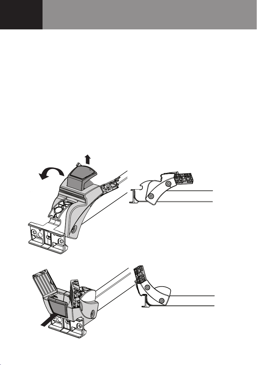
Step 1 – Rotate the Hinges into the open position
1.1 Place the spreader and hinge assembly on a flat surface.
1.2 Pull the latch out firmly (Fig. 3).
1.3 Whilst holding the latch out, rotate the hinge to the ‘open’ position
until the latch ‘clicks’ into place (Fig. 4).
1.4 Repeat at other end.
FD12000 - LINE ART
Pull out latch
Rotate hinge
Closed position
Fig 3
FD12000 - LINE ART
Latch
‘click’
into place
Open position
Fig 4
Pull out latch
Rotate hinge
Latch
'click'
into place
Closed position
Open position
Fig. 3
Fig. 4
5
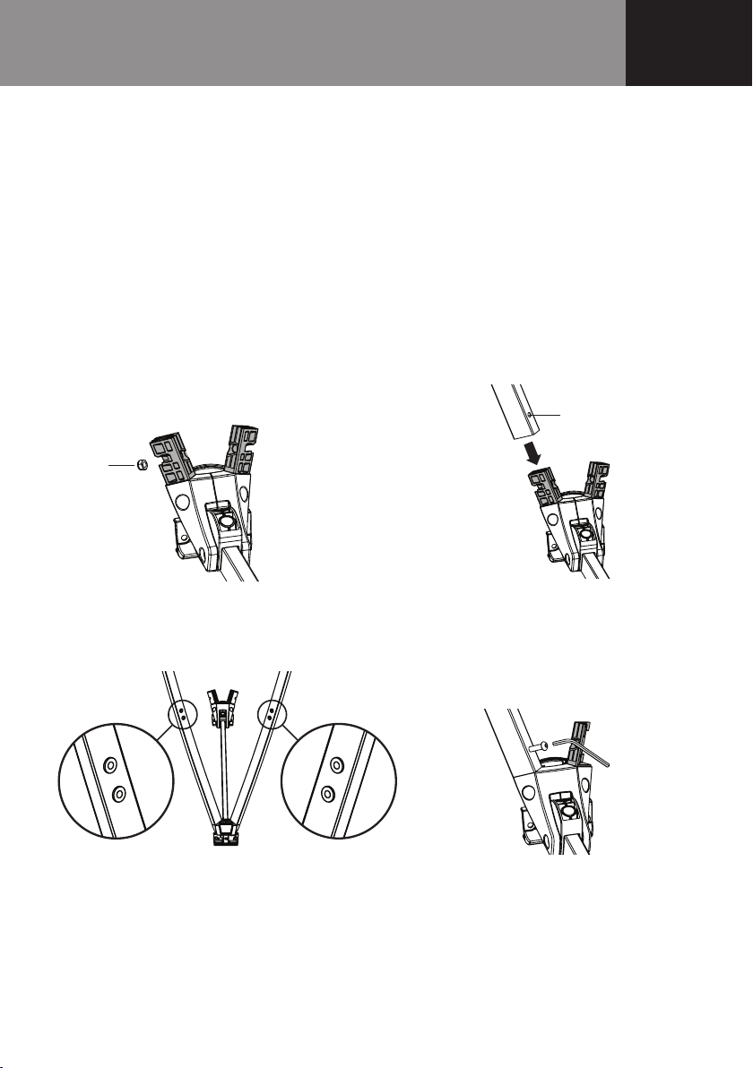
Step 2 – Attach the Legs to the Hinge Assemblies
2.1 Fasten the legs as shown in Steps 1-4.
Step 1 Locate the M6 nut on the moulded leg section of the hinge moulding (Fig. 5).
*Nylon ring of the nut must face outward.
Step 2 Fit the leg tube (ensuring mount hole is oriented as shown in Fig. 6).
Note: Check leg orientation (as per diagram in Fig. 7) to ensure the threaded
inserts for securing the leg brace are facing each other.
Step 3 Insert and fasten securely the M6 x 30 button head screws using the hex key (Fig. 8).
Step 4 Repeat for all legs.
Installation
FD12000 - LINE ART
M6 Nyloc nut*
Threaded inserts Threaded inserts
Fig 5
Fig 7
Step 1 Step 2
Step 3 Step 4
Fig 6
Fig 8
Mount hole
FD12000 - LINE ART
M6 Nyloc nut*
Threaded inserts Threaded inserts
Fig 5
Fig 7
Step 1 Step 2
Step 3 Step 4
Fig 6
Fig 8
Mount hole
Step 1
Step 3
Fig. 5
Fig. 7
FD12000 - LINE ART
M6 Nyloc nut*
Threaded inserts Threaded inserts
Fig 5
Fig 7
Step 1 Step 2
Step 3 Step 4
Fig 6
Fig 8
Mount hole
FD12000 - LINE ART
M6 Nyloc nut*
Threaded inserts Threaded inserts
Fig 5
Fig 7
Step 1 Step 2
Step 3 Step 4
Fig 6
Fig 8
Mount hole
Step 2
Step 4
Fig. 8
Fig. 6 Mount Hole
Threaded inserts
Threaded inserts
M6
Nyloc
nut*

6Installation
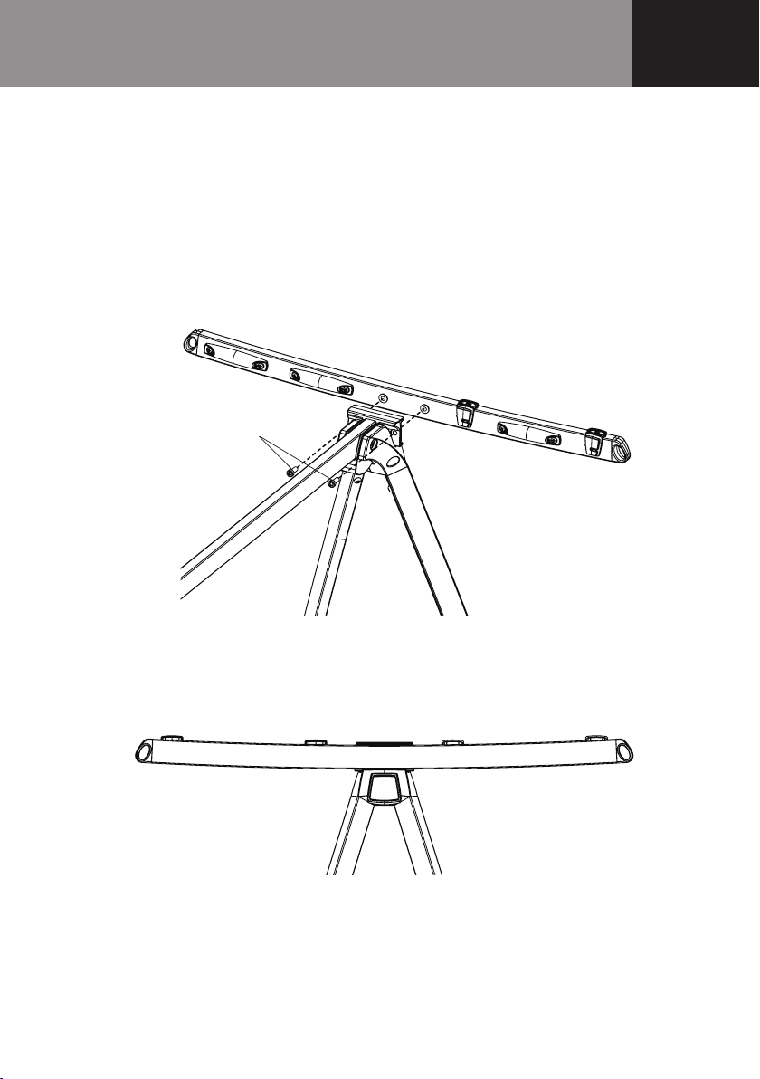
Step 3 – Attach the Brace to the Legs
3.1 Using the M6 x 16 countersunk screws, attach the Leg Brace to the 4 threaded inserts,
using the hex key (Fig. 9).
3.2 Fasten securely.
3.3 Repeat at other end.
Step 4 – Turn the Portable Clothesline over and stand on the ground
as shown (Fig. 10).
FD12000 - LINE ART
Fig 10
FD12000 - LINE ART
Leg
Threaded insert
Leg brace
M6 x 16 countersunk screws
Fig 9
Fig. 9
Fig. 10
Leg
Leg Brace
M6 x 16
countersunk screws
Threaded insert
7
Installation
Step 5 – Attach the Arms
5.1 Locate the arms into the recess in each end of the Hinge Assemblies, ensuring the screw holes
and insert fasteners align.
5.2 Insert the M6 x 12 low profile screws and fasten securely using the hex key (Fig. 11).
Note: Ensure the arms are assembled with the curve up (Fig. 12).
FD12000 - LINE ART
Low prole screws
Fig 11
FD12000 - LINE ART
Arms correctly assembled curve up
Fig 12
Low profile screws
Arms correctly assembled curve up
Fig. 12
Fig. 11
8
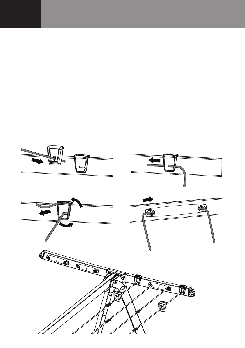
Step 6 – Attach the Line
6.1 Fasten the line to the innermost line tensioner as shown in steps 1-11.
Step 1 Thread a line tie o cap onto one end of the PVC line (Fig. 13).
Step 2 Insert the line into the slot of an inner line tie o saddle and through the side
(Fig. 14). Pull through 15cm+ of excess line for tensioning.
Step 3 Loop the line around the groove in the line tie o saddle (Fig. 15).
Pull tight to prevent the line from slipping.
Step 4 Feed the line through the line’s sleeves (Fig. 16).
Note: It is useful to kink or twist the line when feeding it through the line sleeves
to make assembly easier.
Step 5 Continue feeding the line through the line sleeves’ ensuring all lines are parallel.
Refer to Fig. 17 for the threading pattern for your product.
FD12000 - LINE ART
Fig 13 Fig 14 Fig 18 Fig 19
Fig 20
Fig 22
Fig 21
Fig 15
Fig 17
Fig 16
Line tensioner inner
Line sleeve
Cover cap
Line tensioner outer
FD12000 - LINE ART
Fig 13 Fig 14 Fig 18 Fig 19
Fig 20
Fig 22
Fig 21
Fig 15
Fig 17
Fig 16
Line tensioner inner
Line sleeve
Cover cap
Line tensioner outer
FD12000 - LINE ART
Fig 13 Fig 14 Fig 18 Fig 19
Fig 20
Fig 22
Fig 21
Fig 15
Fig 17
Fig 16
Line tensioner inner
Line sleeve
Cover cap
Line tensioner outer
FD12000 - LINE ART
Fig 13 Fig 14 Fig 18 Fig 19
Fig 20
Fig 22
Fig 21
Fig 15
Fig 17
Fig 16
Line tensioner inner
Line sleeve
Cover cap
Line tensioner outer
Installation
Fig. 13
Fig. 15
Fig. 14
Fig. 16
FD12000 - LINE ART
Fig 13 Fig 14 Fig 18 Fig 19
Fig 20
Fig 22
Fig 21
Fig 15
Fig 17
Fig 16
Line tensioner inner
Line sleeve
Cover cap
Line tensioner outer
Fig. 17
Line tensioner inner
Cover cap
Line sleeve
Line tensioner outer

9
Step 6 When you reach the tie o end of the line, thread another line tie o cap (Fig. 18).
Step 7 Insert the line into the slot of the last line tie o saddle (Fig. 19).
Warning: Do not tighten the line yet.
Step 8 Repeat steps for the other side.
Step 9 Tighten the line on each side by pulling it ‘through’ the line sleeves and repeating
the tie o procedure with the outer line tensioner.
Note: Do not over tighten the line, as you can distort the frame.
Step 10 Trim o excess PVC line at dotted line (Fig. 20). Make sure the line is firmly pulled
back into the line tie o saddle.
Step 11 Push the PVC line end securely into the saddle (Fig. 21).
Step 12 Fit the line tie o caps over the line tie o saddles (Fig. 22).
Your Portable Clothesline is now ready to use.
FD12000 - LINE ART
Fig 13 Fig 14 Fig 18 Fig 19
Fig 20
Fig 22
Fig 21
Fig 15
Fig 17
Fig 16
Line tensioner inner
Line sleeve
Cover cap
Line tensioner outer
FD12000 - LINE ART
Fig 13 Fig 14 Fig 18 Fig 19
Fig 20
Fig 22
Fig 21
Fig 15
Fig 17
Fig 16
Line tensioner inner
Line sleeve
Cover cap
Line tensioner outer
FD12000 - LINE ART
Fig 13 Fig 14 Fig 18 Fig 19
Fig 20
Fig 22
Fig 21
Fig 15
Fig 17
Fig 16
Line tensioner inner
Line sleeve
Cover cap
Line tensioner outer
FD12000 - LINE ART
Fig 13 Fig 14 Fig 18 Fig 19
Fig 20
Fig 22
Fig 21
Fig 15
Fig 17
Fig 16
Line tensioner inner
Line sleeve
Cover cap
Line tensioner outer
Fig. 21
Fig. 19Fig. 18
Fig. 22
Fig. 20
FD12000 - LINE ART
Fig 13 Fig 14 Fig 18 Fig 19
Fig 20
Fig 22
Fig 21
Fig 15
Fig 17
Fig 16
Line tensioner inner
Line sleeve
Cover cap
Line tensioner outer
Installation

10
Step 7 – Line tensioning
To re-tension lines if required:
7.1 Remove either cover cap on the arm.
7.2 Untie the existing line.
7.3 Repeat steps as described on pages 8 and 9.
Note: Do not over tighten the line, as you can distort the frame.
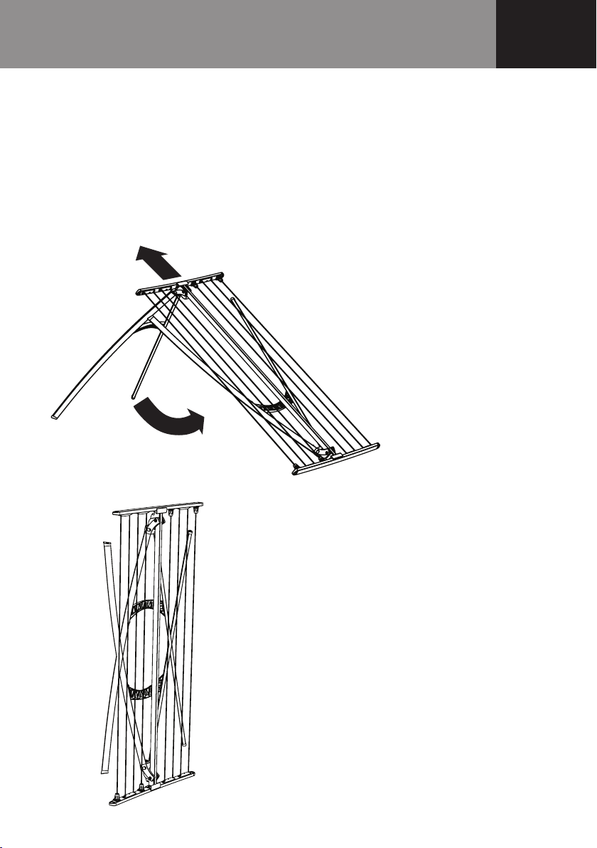
Step 8 – Folding and Unfolding
8.1 To fold away your Portable Clothesline, pull the latch out firmly with one hand,
while supporting and rotating the legs up and around with your other hand.
Keep rotating until the latch ‘clicks’ back into place, locking the legs closed (Fig. 23).
FD12000 - LINE ART
Fig 23
Pull to
release
latch
Fig. 23
Installation
Pull to
release
latch
11
8.2 Place the folded end on the ground (Fig. 24).
8.3 Release the latch at the other end, and fold the legs, while bringing the product
to a vertical position (Fig. 25).
Note: Check the legs are not caught in the lines before trying to unfold.
Always ensure your hands are positioned where they will provide support
and will not be caught in moving parts.
FD12000 - LINE ART
Fig 22
FD12000 - LINE ART
Fig 23
Fig. 24
Fig. 25
Installation

12
Step 9 – Hanging Bracket
To hang your Portable Clothesline for convenient storage, a hanging bracket has been
included (Fig. 26).
9.1 The hanging bracket can be fastened to almost any wall or vertical surface, using appropriate
fasteners (not supplied).
The hanging bracket and door adaptor can be used over most doors.
9.2 Simply place the hanging bracket and door adaptor over your door.
Place the Portable Clothesline on the hanging bracket, ensuring it is centred on the door and
does not make contact with door handles, surrounding furniture and walls, when the door is
opened and closed (Fig. 27).
Secure the door adaptor to the top of the door with the small screw provided.
Note: Check there is clearance between the top edge of the door and door frame for the
door adaptor and screw before fixing.
FD12000 - LINE ART
Fig 26
Check clearance
Installation
FD12000 - LINE ART
Fig 1
Spreader and Hinge Assembly
Arm Assembly
Leg Brace
Line
Leg Assembly LH Leg Assembly RH
Door Adaptor
Hanging Bracket
Hanging Bracket
Fig. 26
Fig. 27
Check clearance

13
Hills Handy Hints
Heavy or large items like thick towels, sheets and quilts can be dried on the Portable Clotheslines.
We recommend placing them over the inner lines, leaving the outer lines for smaller objects.
We also recommend spreading the load over two lines to allow more air circulation for faster
drying. Sheets can be folded in half and dried over two lines.
Quilts can be dried by laying them over the Portable Clothesline then pegging the ends/corners
together to lift them o the floor. When placing washing on the Portable Clothesline, ensure the
weight is balanced and washing is placed evenly on both sides.
The Hills Portable Clothesline can be used almost anywhere but should not be used in strong
wind conditions unless it is placed in a protected area and secured.
The Hills Portable Clothesline can be stored when not in use.
The brace that supports the legs includes holes that provide additional hanging space.
Place pegs over the seams in your clothing to avoid or minimise peg marks on the fabric.
Care and Maintenance
It is a good idea to occasionally inspect all components and check for wear and tear or damage.
The Portable Clothesline should be periodically wiped clean with a damp cloth and
mild detergent.
Handy Hints and Maintenance

14 Warranty
10-Year Warranty*
*In addition to other rights and remedies that
may be available under any applicable law,
AMES Australasia Pty Ltd warrantstothepurchaser
of the product (customer) that this Clothesline
will be free from defects in workmanship and
materials for 10 yearsand the Polycore Line
for 1 year from the date of purchase of the
product. If a defect in material or workmanship
becomes evident during that period, AMES
Australasia Pty Ltd will, at its option, either:
•replace the product; or
•refund tothe customer thepurchase price
paid by the customer for theproduct.
In the event of such a defect, the product
should be returned to the place of purchase
of the product bythecustomer, together
with proof of purchase, for replacement or
refund. Any handling and transportation (and
other expenses incurred in claiming under this
warranty) are not covered bythis warrantyand
will be borne by the customer, not AMES
Australasia Pty Ltd.
The obligation of AMES Australasia Pty Ltd under
this warranty is limited to the circumstances set
out above and is subject to:
•theproduct not having been altered,
tampered with or otherwisedealt with by any
person in a manner other than as intended in
respect of the relevant product; and
•theproduct not having been used or applied
in a manner that is contrary to customary
usage or application of the relevant product
or contraryto anystated instructions or
specification of AMES Australasia Pty Ltd (orits
related bodiescorporate).
For products purchased in Australia:
Our goods come with guarantees that cannot
be excluded under theAustralian Consumer
Law. You are entitled to a replacement or
refund for a major failure and compensation
for any other reasonably foreseeable loss or
damage. You are also entitled tohave the goods
repaired or replaced if the goods fail to be of
acceptable quality and the failure does not
amount to a major failure.
For products purchased in New Zealand:
Our goods come with guarantees that cannot
be excluded under theConsumer Guarantees
Act. AMES Australasia Pty Ltd will comply with
our obligations to youunder the Consumer
Guarantees Act.
AMES Australasia Pty Ltd
ABN 89169 427 061
Level1, 660 Doncaster Road,
Doncaster Vic3108
Phone: 1300 300 564
Email: hhl.enquiries@amesau.com

15
Hills Contacts
We are committed to providing you with
complete customer satisfaction. If you have any
questions or comments about our products or
services please contact your nearest Customer
Service Centre during their local business hours:
Australia
1300 300 564
New Zealand
0800 021 027
Email
Hills Websites
hillshome.com.au
Hills Home Living
hillshome.com.au/need-help/
Hills Consumer Advice
Contacts

AMES Australasia Pty Ltd
A.B.N. 89 169427 061
Issue Mar 2019
HD10777c
Other manuals for Portable 120
1
This manual suits for next models
1
Table of contents
Other Hills Household Appliance manuals

Hills
Hills Rotary 400 User guide

Hills
Hills FD52007 User manual

Hills
Hills Portable 120 User manual

Hills
Hills Hoist 8-Line User manual

Hills
Hills Supa Fold 230 User manual

Hills
Hills Premium Rotary 6 User manual

Hills
Hills Everyday Rotary 37 User manual

Hills
Hills HILLS HERITAGE 5 User manual

Hills
Hills Supa Fold Post Kit Standard - Adjustable... User manual

Hills
Hills Supa Fold 230 User manual


