Hillsboro 2500 Series User manual
Rev. C (8-16)
Form 223
Dominating in Quality, Excelling in Class
220 Industrial Road
Hillsboro, KS 67063
FX 620.947.3127
PH 800.835.0209
Hillsboro
Industries
Series 2500/3500
Aluminum Truck Bed
Owner’s Manual
w w w . h i l l s b o r o i n d u s t r i e s . c o m
Note: new bed installation instructons
For SN 38000 & UP


SERIES 2500/3500 ALUMINUM TRUCK BED
OWNER'S MANUAL
Table of Contents
GENERAL SAFETY RULES ............................................................................................................Page 1
HITCH RATINGS.......................................................................................................................... Page 2-3
SERIES 3500 TOOL BOX INFORMATION ....................................................................................Page 3
COMPLIANCE WITH SAFETY STANDARDS.................................................................................Page 4
Notes on FMVSS 105 ..........................................................................................................Page 4
Notes on FMVSS 108 ..........................................................................................................Page 4
Notes on FMVSS 111 ..........................................................................................................Page 4
BED INSTALLATION .......................................................................................................................Page 5
Adjusting Stinger Width........................................................................................................Page 5
Attaching Bed to Truck Frame .............................................................................................Page 6
Headache Rack Height & Adjustment .................................................................................Page 7
WIRING.............................................................................................................................................Page 7
Wiring Harness Diagram......................................................................................................Page 8
LED Lighting ........................................................................................................................Page 9
Adapter and LED Reference Chart....................................................................................Page 10
FUEL DOOR AND FILLER INSTALLATION.................................................................................Page 11
WARRANTY ...................................................................................................................................Page 12
Copyright 2016 by Hillsboro Industries
Manufacturer's Notice: All specifications are subject to change without notice
and without incorporating them into prior units.
This Manual contains cautions that are marked with the safety alert symbol. All
cautions should be carefully read and obeyed!
WARNING: This unit is not designed to provide protection for fuel
tanks mounted outside of the vehicle frame. Do not mount this unit
on a vehicle equipped with fuel tanks mounted outside of vehicle
frame.
GENERAL SAFETY RULES
Read and understand the Owner's Manual and all safety signs before installing or operating this product.
DO NOT modify truck bed length, width, or height nor obscure lighting provided on the truck
bed.
Observe all warnings and recommendations as specified in the vehicle manufacturers manual or
incomplete vehicle manual.
Use caution when working around fuel tanks and fuel lines. Avoid ignition sources.
Always wear protective clothing and eyewear when operating tools. Observe safe weld procedures and
also safe tool operation as specified in tool operating instructions.
Check that all lights are functioning properly before operating vehicle.
Page 1

Hitch Ratings
Truck Bed Gooseneck Hitch Ratings
If this truck bed is equipped with a factory-installed gooseneck hitch, when the truck bed is
properly mounted to a truck, this hitch has the following ratings:
Maximum Gross Trailer Weight = 30000 lbs.
Maximum Vertical Tongue Load = 6000 lbs.
Hitch Ball Size = 2-5/16 in.
These ratings apply to the hitch components only. Actual towing capacity may be lower de-
pending on the tow vehicle or installed equipment. Refer to the tow vehicle (truck) documen-
tation for vehicle towing capacity ratings.
Do not exceed the towing ratings of this hitch or the tow vehicle.
Do not cut, drill, weld or modify any hitch components except as defined in
the bed mounting instructions.
Optional B&W Accessory Compatibility and Ratings
This Hillsboro truck bed can be equipped with the Hillsboro B&W socket kit which provides
compatibility with available B&W accessory items. This kit may be purchased separately.
The Hillsboro B&W socket kit includes the B&W 2-5/16 turnover ball which projects from the
bed surface.
Hillsboro B&W Socket Kit - Hillsboro part number 74790
Maximum Gross Trailer Weight = 30000 lbs.
Maximum Vertical Tongue Load = 6000 lbs.
Hitch Ball Size = 2-5/16 in.
B&W has several accessory items available for use with the Hillsboro B&W socket kit. The
tow ratings of the Hillsboro truck bed with these items installed will never exceed the ratings
above and may be lower as defined below. Never exceed the rating stated by B&W for any
accessory item. Do not exceed the towing ratings of the tow vehicle
Approved B&W accessory items for use with the Hillsboro B&W socket kit:
MGTW = Maximum Gross Trailer Weight, lbs.
MVTL = Maximum Vertical Tongue Load, lbs.
B&W Part # Description MGTW MVTL
RVK3050 Companion Flatbed 5th Wheel 22000 5500
GNXA4000 Kingpin 30000 6000
GNXA4085 4” Extender 20000 5000
GNXA4075 Eyelet 30000 6000
GNXA4025 Inverted Ball 30000 6000
GNXA2050 Hi-Rise Ball 2-5/16” 20000 5000
Page 2

Hitch Ratings
Truck Bed Receiver Hitch Ratings
If this truck bed is equipped with a factory-installed receiver hitch, when the truck bed is properly
mounted to a truck, this hitch has the following ratings:
Weight Carrying Hitch Configuration
Maximum Gross Trailer Weight = 18000 lbs.
Maximum Vertical Tongue Load = 1800 lbs.
Weight Distributing Hitch Configuration
Maximum Gross Trailer Weight = 18000 lbs.
Maximum Vertical Tongue Load = 1800 lbs.
These ratings apply to the hitch components only. Actual towing capacity may be lower depend-
ing on the tow vehicle or installed equipment. Refer to the tow vehicle (truck) documentation for
vehicle towing capacity ratings.
Do not exceed the towing ratings of this hitch or the tow vehicle.
Do not cut, drill, weld or modify any hitch components except as defined in
the bed mounting instructions.
Page 3
Series 3500 Tool Box Information
WARNING: Do not place flammable, combustible or living object in tool
boxes. Proximity to vehicle exhaust can create high temperatures in tool
boxes.
Maximum allowable weight in tool boxes is 200lbs. Weight must be uniformly distributed over the box
floor.
CAUTION: Do not place corrosive objects in tool boxes.

COMPLIANCE WITH SAFETY STANDARDS
It is the responsibility of the final stage manufacturer (installer) to certify that the completed
vehicle complies with applicable Federal Motor Vehicle Safety Standards (FMVSS) by
properly completing and applying a final stage manufacturer certification label to the vehicle.
Notes on FMVSS 105
Installation of a Hillsboro Truck Bed must be in compliance with FMVSS 105 with respect to
vertical and horizontal Center of Gravity. Refer to the Incomplete Vehicle Manual and the
table below. The weights listed below include the weight of the hitch ball plate assembly. It
adds 90# to the bed weight. The vertical Center of Gravity is 2” below the top surface of the
bed floor. Determine the horizontal Center of Gravity from the following table:
Notes on FMVSS 108
Installation of a Hillsboro Aluminum Truck Bed results in a vehicle with an overall width
greater than 80 inches. To comply with FMVSS 108, "Lamps, Reflective Devices and
Associated Equipment", the completed vehicle must have identification lights, amber facing
front and red facing rear, centered on the vertical centerline of the vehicle. Identification
lights consist of three lights on the same level, as close as practicable to the top of the vehicle
with lamp centers spaced not less than 6 inches or not more than 12 inches. Your Aluminum
Truck Bed is equipped with red identification lights facing rearward.
Notes on FMVSS 111
Installation of a Hillsboro Aluminum Truck Bed may affect compliance with FMVSS 111,
"Rearview Mirrors". Information concerning rearview mirrors and compliance with FMVSS
111 may be obtained from the vehicle manufacturer's Incomplete Vehicle Manuals and Body
Builder's Books.
Model Weight
Horizontal Center of Gravity
from Rear of Bed
ALT 81W X 86L S2500 548 39-3/4
ALT 81W X 102L S2500 608 46
ALT 81W X 112L S2500 623 51
ALT 96W X 86L S2500 592 39-3/4
ALT 96W X 102L S2500 658 46
ALT 96W X 112L S2500 675 51
ALT 96W X 136L S2500 763 61-1/4
Page 4
BED INSTALLATION
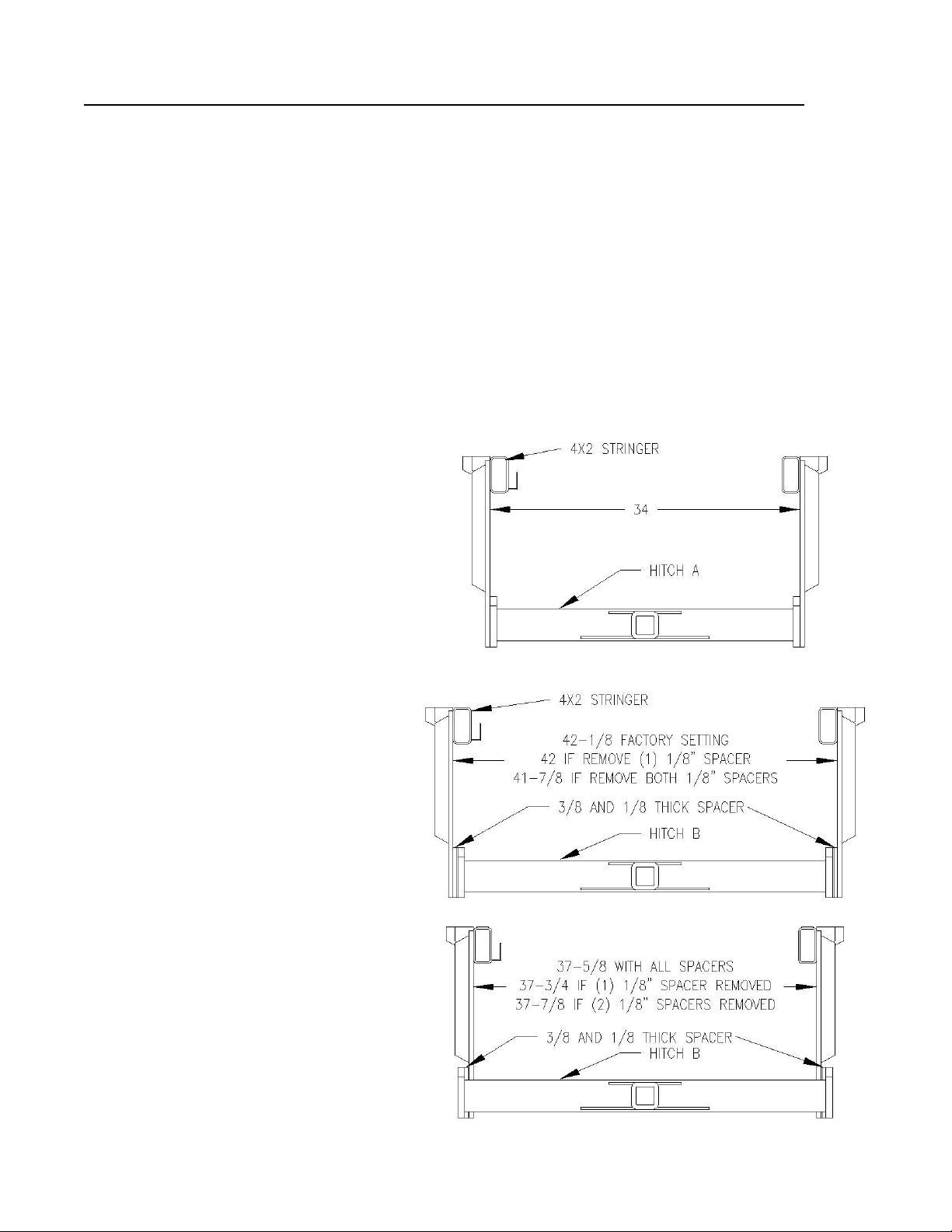
Adjusting Stringer Width
The series 2500 truck bed comes with adjustable width 4”x2” stingers. On 86” and 102”
long beds (for pickup box removals), the stringers are factory set for the 42” frame width
trucks. On 112” and longer beds, stingers are factory set for 34” frame width trucks.
Before installation, verify truck frame width. The truck frame should measure roughly 34”,
37-5/8” or 42”, depending on make and year of truck. Outside surfaces of the stingers
must match truck frame width. On most trucks, the 1/2” rear receiver hitch plates that
drop from the stingers will overlap the truck frame at the rear and at installation they will
be bolted to the truck frame. Therefore, the stingers need to be just wide enough to allow
the 1/2” plates to clear the truck frame. Even if the stingers are already in the correct po-
sition, the hitch bolts and the bed mounting bolts may need to be temporarily loosened to
allow the bed to freely slide over the rear of the truck frame.
On some trucks it will be necessary to
adjust stinger width. First, remove the
(8) 5/8” bolts and remove the receiver
hitch assembly and spacer plates.
Next, remove the 1/2” bolts that attach
stingers to the gooseneck plate and to
the aluminum bed. The aluminum bed
mount brackets and gooseneck plate
have holes for all 3 width settings.
Move stingers to the appropriate loca-
tion and reinstall 1/2” hardware.
The drawing on this page shows the
rear receiver hitch and how to position it
and the spacer plates to match the truck
frame width. “Hitch A” (34” wide) can
only be used in the 34” setting and does
not use spacer plates. “Hitch B” (41”
wide) is used for the 37-5/8 and the 42”
setting and uses spacer plates. As the
drawing shows, the 1/8” spacer plate on
each side can be removed as needed to
exactly match the truck frame width.
Reinstall and tighten hardware. Torque
nuts to 65 ft. lbs. for 1/2” hardware and
110 ft lbs for 5/8” hardware.
Special applications may require the
other hitch than what is included with
the bed. These are available as kits
through Hillsboro Industries and our
dealers.
Page 5
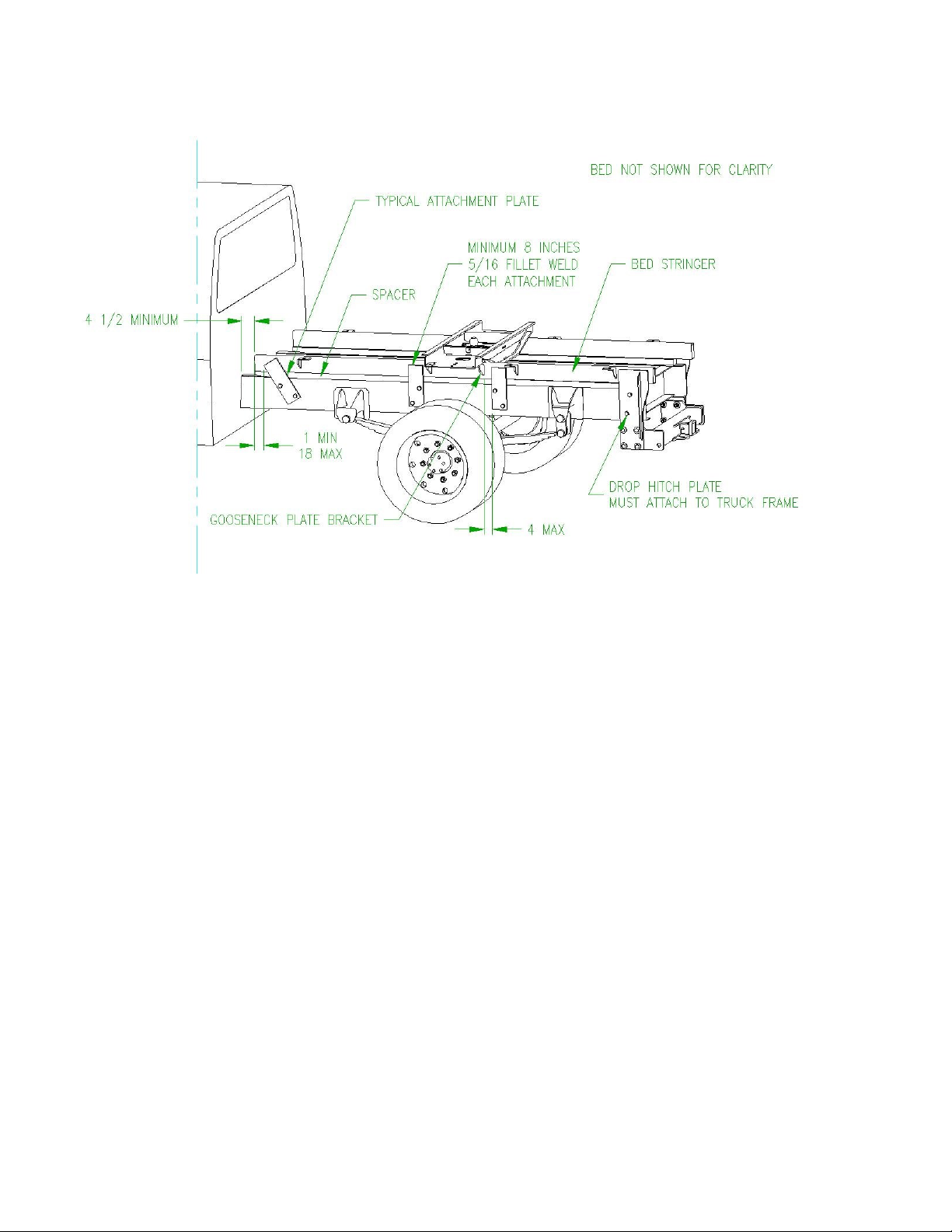
Attaching Bed to Truck Frame
Position the bed on top of the truck frame. The front of the stringers shall be no closer than 4 1/2”
to the vehicle cab. This should create a 3” gap between the headache rack and the cab. (This is
the truck OEM recommended minimum distance) Stringers may need to be spaced off the frame
to allow adequate clearance for vehicle components operating under the bed. Refer to the truck
manufacturer’s Body Builder Guide for spacer recommendations. Check for proper clearance to
vehicle components located under the bed.
Determine the stringer attachment points on your vehicle. Attachment components are not
supplied. Each stringer must be attached to the vehicle frame at a minimum of four places. The
front attachment must locate between 1 and 18 inches from the end of the stringer. The center
attachments must be located from 0 to 4 inches from each end (front and rear) of the gooseneck
plate bracket. The rear attachment should be made through the 1/2” drop hitch plate. If the truck
frame is not long enough to attach through the drop hitch plate, extend the truck frame to reach
the drop hitch plate or add material to the front of the drop hitch plates to reach the truck frame.
Each attachment should be a minimum 3/8 inch thick hot rolled steel plate. Do not trim, notch or
alter attachment plates in any way that would weaken the attachment joint. The plates should be
welded to the stringers with a minimum of 8 inches of 5/16 fillet weld. Observe safe weld
procedures. The plates should be bolted to the truck frame. Most frames have existing holes that
can be used. If it is necessary to drill holes in the truck frame, refer to the truck manufacturer’s
Body Builder Guide for allowable size and location for holes. Each plate will require a minimum of
two 5/8” Grade 5 bolts. Bolts may be located no closer than 4 inches on-center and 1 inch from
any edge of the attachment plates or the rear hitch plate.
Page 6

Headache Rack Height Adjustment
If the headache rack is too tall for your truck, it can be lowered 2-1/2”. Remove the 2-1/2”
formed riser channel by removing the 8 bolts that secure it. Remove the 4 bottom bolts on
each side that bolt the diamond plate headache rack gusset to the headache rack mounts.
Lower the headache rack down to the bed and reinstall end bolts. Re-install the 4 bolts
that hold the headache rack panel to the bed.
WIRING
NOTE: Observe all vehicle manufacturer recommendations when working with or
connecting to vehicle electrical system. Keep all lights turned off when making electrical
connections.
This harness is designed for either combined or separate stop/turn signals. To connect to
the harness, all trucks require a make specific adaptor. Although 1999-2010 Ford trucks
will plug into the harness, an adaptor is required for the lights to function properly. To
purchase an adaptor, contact the selling dealer or Hillsboro Industries. Please refer to
the chart on page 8 for adapter part numbers.
NOTE: On newer Dodge trucks (box removal), all truck harness wires cut during box
removal must be connected to a corresponding light in the bed. Failure to do so may result
in a “light out” message on the dash.
Verify that vehicle lighting systems function properly and comply with FMVSS 108 and
vehicle manufacturer recommendations.
Gooseneck Ball Plate Adjustment
When adjusting the stingers to match frame width you will need to un-bolt the
gooseneck ball plate. After the stingers have been adjusted to the correct width the goose-
neck ball plate should then be reattached using the same 1/2” hardware and torque to 65
ft. lbs. The ball should be oriented so it is closer to the headache rack, this is to provide
proper weight distribution of the trailer tongue weight.
Page 7
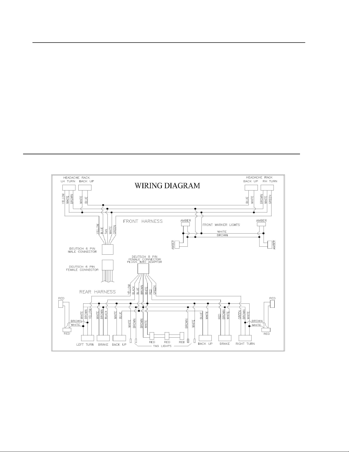
Wiring Harness Diagram
Separate Stop/Turn
Color Combined Stop/Turn (2003-2005 Dodge, 2003-2007 GM)
White Ground Ground
Brown Marker Rear Marker Rear
Tan Marker Front Marker Front
Blue Backup Backup
Green RH Turn/Brake RH Turn
Yellow LH Turn/Brake LH Turn
Red RH Turn/Brake Brake
Black or Purple LH Turn/Brake Brake
Page 8

Trailer Electrical Socket
Hillsboro extruded floor aluminum
truck beds are equipped with two holes in
the gooseneck ball plate. One of these holes
is to be used for running a pigtail with a trail-
er electrical socket on the end. This pig tail
should be 1-2 foot long so that it can be
coiled in the ball plate box and covered with
the gooseneck hitch lid when it is not being
used. The provided grommet should be
used in the hole selected for the pigtail, also
zip ties should be used on both sides of the
grommet to keep the desired length of plug
in the ball plate box to prevent dragging.
When a trailer is attached route the pigtail
so that is not damaged by the safety chains
or trailer coupler.
LED Lighting
Turn Signal Fast Flash Rate
Because LEDs draw significantly less current than traditional incandescent lamps (as low as
1/10th), using LED lights in a Hillsboro Truck bed can cause a fast flash rate of the turn signal
circuits. The fast flash rate can be corrected in a couple of different ways depending on the
make and year of the truck. Please refer to the table on the next page for more information.
LED Resistor Harness
Please refer to the table on the next page to see if resistor harnesses are needed to correct
the turn signal fast flash rate.
Hillsboro Industries has developed a LED resistor harness (part number 233805) that plugs in
between the LED light and the Hillsboro truck bed wiring harness. The resistor harness con-
tains a 6 ohm 50 watt power resistor. The resistor draws the same current (appx. 2 amps) as
the original incandescent light and therefore the turn signals flash at the correct rate.
To install the resistor harness, plug it in between the LED stop/turn/tail light and the Hillsboro
truck bed harness. The power resistor gets very hot during operation and needs to be mount-
ed to a metal surface (preferably aluminum) which acts as a heat sink. Make sure that
all wiring is kept clear of the resistor and heat sink.
Page 9

Adapter and LED Reference Chart
Page 10
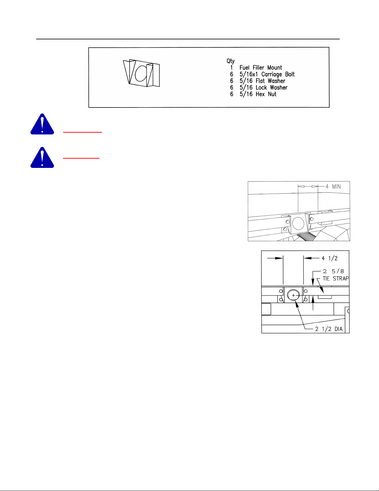
FUEL FILLER INSTALLATION
WARNING: Keep all ignition sources away from vehicle when working with Fuel
Tank Filler Pipe.
CAUTION: Fuel Tank Filler Pipe must be installed according to vehicle
manufacturer requirements. Follow all warnings and cautions within the vehicle
manual.
Locate and identify all components supplied with the Fuel
Filler Mounting Kit. Hardware is packaged in a padded
envelope. Determine the desired location along the side of
the bed for the fuel filler installation. Location must avoid
interference of fuel tank fill tube with bed crossmembers and
be no closer than 4 inches to any stake pocket. Mark
selected filler centerline on tie strap and bed.
Remove 4 1/2 inches of tie strap centered on fuel filler
centerline. Cut a 2 1/2 inch diameter hole in the side of the bed
located on fuel filler centerline and 2 5/8 inches downward from
the top surface of bed. Remove all burrs remaining after
cutting.
Insert fuel tank fill pipe through hole in bed side. Connect fuel
tank fill pipe to tank according to vehicle manufacturer
requirements.
Slide fuel filler mount down from the top behind tie strap and
over fuel fill pipe, until the top of the mount is flush with the top of tie strap. Clamp fuel filler
mount in place. Drill upper 3/8 inch holes through tie strap, both flanges of filler mount, and bed.
Upper holes are centered vertically on the tie strap and 1/2 inch from cut edge, 2 places. Drill
lower 3/8 inch holes through filler mount and bed. Lower holes are 3/8 inch from bottom and
edge of filler mount, 2 places.
Install carriage bolts from outside. Install flat washer, lock washer and hex nuts, 6 places.
Tighten nuts to approximately 13 ft. lbs. Fasten fuel filler pipe flange to filler mount as required
by vehicle manufacturer specifications.
Page 11

MANUFACTURER’S WARRANTY
Aluminum Truck Bed Products from
Hillsboro
Industries
Hillsboro Industries (HI) warrants the aluminum frame of its aluminum truck bed product line against
structural failure (including weld failure) for (3) three years from the date of purchase by the original owner.
This includes weld failures and failure of extrusions, decking and headache rack.
Warranty on any HI product used by the customer in the transportation of goods for compensation or in
rental enterprises will be one-half of the above-stated length.
This warranty applies to the original owner only. All warranty claims must be submitted through an
authorized HI dealer for processing.
Hillsboro Industries will not be responsible for any damage caused by the abuse, misapplication or misuse
of their products.
Any part or workmanship, subject to this warranty, if defective, as determined solely by HI, will be repaired
or replaced, at the option of HI, without charge. Photos may be required by HI to assess extent of damage.
If repairs or replacements are made at a location other than HI, reimbursement to the original owner will be
made at an amount not to exceed the amount HI would charge for the parts and labor. All parts for
warranty consideration must be returned to Hillsboro Industries* freight prepaid. All warranty claims must
be filed with HI no later than 30 days after the warranty period expires.
COMPONENTS NOT MANUFACTURED BY HI MAY BE COVERED BY THE WARRANTY OF THEIR
RESPECTIVE MANUFACTURERS, BUT ARE NOT COVERED BY THE HI WARRANTY.
HOW TO FILE FOR WARRANTY:
• First contact the selling dealer and process the claim through the dealer.
• Any HI product found to have defective material or workmanship must be serviced or corrected through
an authorized HI dealer. All warranties must then be authorized by a Hillsboro Industries factory
representative. Hillsboro Industries will not make reimbursements for any repairs and or adjustments
made without prior written consent from the HI factory.
• Always provide the HI serial number of the truck bed
HI neither assumes nor authorizes any person to create or assume for it any obligation or liability in
connection with its products or to undertake any responsibility to any purchaser for representation or
warranty made by a dealer beyond those expressly set forth herein.
HI shall not be held liable for consequential commercial damages resulting from any breach of this
warranty or any other warranty, all of which are expressly disclaimed, for any delay in the performance of
this warranty due to causes beyond its control.
THESE EXPRESS WARRANTIES ARE IN LIEU OF ANY OTHER WARRANTIES, EXPRESS OR
IMPLIED, INCLUDING THE IMPLIED WARRANTIES OF MERCHANTABILITY OR FITNESS FOR A
PARTICULAR PURPOSE. TO THE EXTENT THAT ANY LIMITATION CONTAINED HEREIN IS
PROHIBITED BY ANY STATE OR FEDERAL LAW, SUCH LIMITATION IS VOID.
For more information see your dealer or contact:
*Hillsboro Industries
220 Industrial Road
Hillsboro, Kansas 67063
Call toll free 1.800.835.0209
Page 12
This manual suits for next models
8
Table of contents
Popular Automobile Accessories manuals by other brands

Boyo
Boyo VTR107 user manual

Abrams
Abrams RUGEYE-X Series Installation and operation manual

Atera
Atera SIGNO 044 437 quick start guide

Fortin Electronic Systems
Fortin Electronic Systems EVO-CAN SUGGESTED WIRING CONFIGURATION

Kargo Master
Kargo Master 40474 installation guide

Classic Accessories
Classic Accessories OVER DRIVE 80-112-012401-00 quick start guide

iSimple
iSimple TranzIt BLU ISFM23 installation instructions

Metra Electronics
Metra Electronics 99-9223 installation instructions

Telefunken
Telefunken TF-DVR32FHD instruction manual

Tessera4x4
Tessera4x4 SOT-ROLL Series installation manual

Xiaomi
Xiaomi Mi 20W Wireless Car Charger quick start guide

Nav TV
Nav TV BMW12-DYNAMIC KIT Install manual


