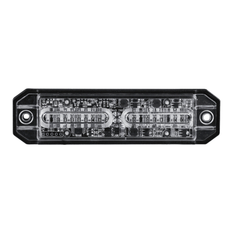
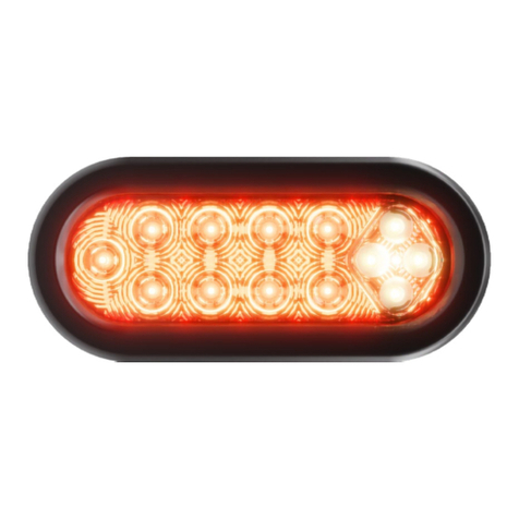
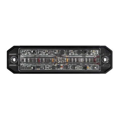
Abrams RUGEYE-X Series User manual

www.abramsmfg.com
RUGEYE-X SERIES
LED Lightbar
Installation and
Operation Manual
Model# RE-47X

Table of Contents
Important & Warning ......................................................................3
RugEye-X Series/ Control Box ......................................................5
Equipment and Dimensions ..........................................................5
Wiring and Functions ......................................................................6
Installing Brackets ............................................................................7
Flash Pattern Operation .................................................................8
Specications ................................................................................. ...9
Troubleshooting............................................................................. 10
Warranty .................................................... ..................................... 11
844.9.ABRAMS
www.abramsmfg.com
info@abramsmfg.com
2Abrams Installaon and Operaon Manual
www.abramsmfg.com | [email protected]om

Warning
Important
FAILURE TO INSTALL OR USE THIS PRODUCT ACCORDING TO MANUFACTURER’S RECOMMENDATIONS
MAY RESULT IN PROPERTY DAMAGE, SERIOUS INJURY, AND/OR DEATH.
PLEASE READ ALL OF THE FOLLOWING
INSTRUCTIONS BEFORE INSTALLING YOUR
NEW ABRAMS PRODUCT.
PROPER INSTALLATION OF THIS PRODUCT
REQUIRES THE INSTALLER TO HAVE A
GOOD UNDERSTANDING OF AUTOMOTIVE
ELECTRONICS, SYSTEMS AND PROCEDURES.
THIS PRODUCT CONTAINS HIGH-INTENSITY
LEDS. DO NOT STARE DIRECTLY INTO THESE
LIGHTS. MOMENTARY BLINDNESS AND/OR
EYE DAMAGE COULD RESULT.
DO NOT INSTALL THIS PRODUCT OR ROUTE
ANY WIRES IN THE DEPLOYMENT AREA OF
YOUR AIR BAG. EQUIPMENT MOUNTED OR
LOCATED IN THE AIR BAG DEPLOYMENT
AREA WILL DAMAGE OR REDUCE THE
EFFECTIVENESS OF THE AIR BAG, OR
BECOME A PROJECTILE THAT COULD
CAUSE SERIOUS PERSONAL INJURY OR
DEATH. REFER TO YOUR VEHICLE OWNER
MANUAL FOR THE AIR BAG DEPLOYMENT
AREA. THE USER/INSTALLER ASSUMES
FULL RESPONSIBILITY TO DETERMINE
PROPER MOUNTING LOCATION, BASED
ON PROVIDING ULTIMATE SAFETY TO ALL
PASSENGERS INSIDE THE VEHICLE.
IF MOUNTING THIS PRODUCT REQUIRES
DRILLING HOLES, THE INSTALLER MUST BE
SURE THAT NO VEHICLE COMPONENTS OR
OTHER VITAL PARTS COULD BE DAMAGED
BY THE DRILLING PROCESS. CHECK BOTH
SIDES OF THE MOUNTING SURFACE BEFORE
DRILLING BEGINS. ALSO DE-BURR ANY
HOLES AND REMOVE ANY METAL SHARDS
OR REMNANTS. INSTALL GROMMETS INTO
ALL WIRE PASSAGE HOLES.
INSPECT AND OPERATE THIS PRODUCT
REGULARLY TO CONFIRM ITS PROPER
OPERATION AND MOUNTING CONDITION.
DO NOT USE A PRESSURE WASHER TO
CLEAN THIS PRODUCT.
FOR THIS PRODUCT TO OPERATE
AT OPTIMUM EFFICIENCY, A GOOD
ELECTRICAL CONNECTION TO CHASSIS
GROUND MUST BE MADE. THE
RECOMMENDED PROCEDURE REQUIRES
THE PRODUCT GROUND WIRE TO BE
CONNECTED DIRECTLY TO THE NEGATIVE (-)
BATTERY POST.
IT IS RECOMMENDED THAT THESE
INSTRUCTIONS BE STORED IN A SAFE PLACE
AND REFERRED TO WHEN PERFORMING
MAINTENANCE AND/OR REINSTALLATION
OF THIS PRODUCT.
FAILURE TO FOLLOW THESE SAFETY
PRECAUTIONS AND INSTRUCTIONS COULD
RESULT IN DAMAGE TO THE PRODUCT OR
VEHICLE AND/OR SERIOUS INJURY TO YOU
AND YOUR PASSENGERS!
IF THIS PRODUCT USES A REMOTE DEVICE
TO ACTIVATE OR CONTROL THIS PRODUCT,
MAKE SURE THAT THIS CONTROL IS
LOCATED IN AN AREA THAT ALLOWS
BOTH THE VEHICLE AND THE CONTROL
TO BE OPERATED SAFELY IN ANY DRIVING
CONDITION.
DO NOT ATTEMPT TO ACTIVATE OR
CONTROL THIS DEVICE IN A HAZARDOUS
DRIVING SITUATION.
844.9.ABRAMS
www.abramsmfg.com
info@abramsmfg.com
3
Abrams Installaon and Operaon Manual
www.abramsmfg.com | [email protected]om

Equipment and Dimensions
Control Box and Wiring Instructions
Warning Pattern switch and Trafc Pattern switch
Package Contents:
RugEye-X Series Lightbar
Abrams Control Box
Universal Mounting Bracket Kit
12 FT Power Cable Harness
Product Installation Manual
IMPORTANT! PLEASE READ THROUGH ALL
PROVIDED INSTRUCTIONS AND ANY LISTED
WARNINGS IN REGARDS TO PRODUCT USE.
1195.5 (47.06) inches
77.3 (3.04) inches
844.9.ABRAMS
www.abramsmfg.com
info@abramsmfg.com
Less than 1 sec. For next pattern
Between 1-3 sec. For previous pattern
4Abrams Installaon and Operaon Manual
www.abramsmfg.com | [email protected]om

Wiring: 2C+6C+7C, 15 Wires
Wires Color Description
Power Wires - 2C Red Vin
Black GND
Function Wires - 6C
Black Aelly Light Flash
Green Cruise
Blue Take Down ON
Orange Warning Pattern
Red Aelly Light ON
Yellow Take Down Flash
Switch Wires - 7C
Green Trafc ON/OFF
Black Warning ON/OFF
Blue Right
Orange Left
White Down
Red Control Box Power Supply
Yellow Trafc Pattern
844.9.ABRAMS
www.abramsmfg.com
info@abramsmfg.com
5
Abrams Installaon and Operaon Manual
www.abramsmfg.com | [email protected]om

10 A Fuse
10~30V
Connect Black Wire to Negative Power (-)
Connect Red Wire to Positive Power (+)
Green Wire to Positive - Right Arrow
Orange Wire to Positive - Left Arrow
Brown Wire to Positive - Warning Mode 1
White Wire to Positive - Warning Mode 2
Purple Wire to Positive - Takedown Mode
Yellow Wire to Positive (Only) - Cruise Mode
(With Other Function) - Dime Mode
Blue Wire to Positive - Flash Pattern Switch
Blue Wire to Negative - Flash Speed Switch
844.9.ABRAMS
www.abramsmfg.com
info@abramsmfg.com
6Abrams Installaon and Operaon Manual
www.abramsmfg.com | [email protected]om

Installing Brackets
Use supplied mounting brackets to attach light bar to the vehicles visor.
Mount the Blitz X-Series Inner Bar using the brackets supplied and user supplied mounting screws.
CAUTION: Be certain that you have selected a mounting location that does not obstruct
the driver’s vision and allows safe operation of the vehicle. Check the chosen mounting
location to ensure that the vehicle’s structure and material is adequate to support the
weight of your light.
FOOT PAD
VEHICLE ROOF
STRAP FOAM
Mounting
Place the full light bar on the top of your vehicle and adjust the feet to t your vehicle according to the zones speci-
ed by the vehicle manufacture.
Light Bars should be mounted a minimum of 12” - 34” from the radio antenna to aviod interference.
If do not know where to mount your bar, seek a professional installer for the installation of your light bar.
attach the gutter mount bracket or vehicle specic bracket to the light bar using the bolt and tighten the bold until
your light bar is secure.
If are using the universal gutter bracket and it does not t your vehicle, you may need to purchase a vehicle specic
bracket.
Once the light bar is secure, drill the bracket to the vehicle’s gutter for a more secure hold.
Wiring
Lower the headliner before drilling by 6” to 8” to protect it from damage caused by drilling the cable access hole.
The light bar’s wire harness will require you to drill a 3/8” hole for the cable access when the connector is not at-
tached
Warning! do not drill through the roof support member which spans between the passenger and drivers side of the
vehicle. Adjust the location where the bar will be mounted to avoid contact with this support member.
Remove all ridges or sharp edges of the hole with a round le. Make sure to de-burr the edges of the hole.
You must use a 3/8” Grommet (User Supplied) into the cable access hold.
Once the cables are fully pulled through, use professional grade silicone to weatherproof the hole.
Route the full length of the cable down towards your switch panel through the base of the B-Piller taking a 90 degree
turn to enter the B-Pillar.
** If you require additional information and / or video and user guides,
please visit www.abramsmfg.com/support or call Abrams Customer Support 844.9 Abrams
844.9.ABRAMS
www.abramsmfg.com
info@abramsmfg.com
7
Abrams Installaon and Operaon Manual
www.abramsmfg.com | [email protected]om

Warning
ON/Off
Warning
Pattern
Trafce
Trafc
ON/Off
Center Dim & Cruise Alley Take Down
Operation
Left Right Dim Cruise On Flash On Flash
1
0 0 0 0 0 0 0 0 0 0 Warning Flash
0
0 1 0 0 0 0 0 0 0 0 Trafc --
Center
0
0 1 – 0 0 0 0 0 0 0 Trafc -- Left
0
0 1 0 – 0 0 0 0 0 0 Trafc -- Right
0/1 0/1
0/1 0/1 0/1 – 0/1 0/1 0/1 0/1 0/1 Dim -- 15%
N/A N/A
N/A N/A N/A N/A –N/A N/A N/A N/A Cruise Mode
-- 15%
0 0
0 0 0 0 0 – 0 0 0 Alley -- ON
0 0
0 0 0 0 0 0 – 0 0 Alley -- Flash
0 0
0 0 0 0 0 0 0 – 0 Take Down
-- ON
0 0
0 0 0 0 0 0 0 0 – Take Down --
Flash
Flash Pattern Operation
844.9.ABRAMS
www.abramsmfg.com
info@abramsmfg.com
8Abrams Installaon and Operaon Manual
www.abramsmfg.com | [email protected]om

Specications
Model Number Ameesa Light Bar
Input Voltage 10 ~ 15VDC
Peak Input Current 20 Amax @12V
Flash Patterns 8 Group + 31 Pattern
Fuse 20A
Storage Temperature Range -40°C~ +50°C
Left Group /Right Group
/Center Group
P1-One Lamp Sequence to Double
P2-Two Lamp Sequence to Double
P3-Six Lamp Sequence to Double
P4-Sequenc to Solid
P5-One Lamp Sequence to Triple
P6-Triple Lamp Sequence to Double
P7-Sequence On to Sequence Off P8-Solid
Arrow
Warning Group
P1- Signal Flash 150FPM. - In-Out 150FRM
P2- In-Out 150FRM
P3- Checker 150FPM - Signal Flash 150FPM -
In-Out 150FRM
P4- Checker 150FPM - Signal Flash 150FPM
P5- Checker 150FPM - In-Out 300FRM
P6- Signal Flash 300FPM. - In-Out 300FRM
P7- Checker 150FPM - In-Out 150FRM
P8- Signal Flash 75FPM. - In-Out 75FRM
P9- Single Flash 75FPM
P10-Single 150 FPM
P11-Double Flash 75FPM
P12-Double Flash 120FPM
P13-Quad Flash75FPM
P14-Quad Flash 150FPM
P15-Single Flash Split 75FPM
P16-Single Flash Split 150FPM
P17-Double Flash Split 25FPM
P18- Double Flash Split 150FPM
P19- QUAD Flash SPLIT 75FPM
P20- QUAD Flash SPLIT 150FPM
P21- Single 600FPM checker
P22- QUAD 150FPM checker
P23- 4 single 150FPM 4 single 300FPM half
P24- 3 single 150FPM 3 double 150FPM 3
single 300FPM half P25- IN OUT 150FPM
P26- IN OUT 75FPM
P27- steady QUAD 150FPM checker
P28- steady QUAD 75FPM checker
P29- Module Checker
P30- Single 75/150/300FPM checker & all on
P31- Auto
844.9.ABRAMS
www.abramsmfg.com
info@abramsmfg.com
9
Abrams Installaon and Operaon Manual
www.abramsmfg.com | [email protected]om

Ambient Temperature: -10 to 45 ° C
Relative Humidity: 10 to 85%, non-condensing
Trouble Shooting
All Manufacture Defects are covered under the Abrams Warranty
accordingly. Warranty is void with disassembly or rewiring of any Abrams
Products or Improper Wiring or Installation. If you are unsure how to trouble
shoot your light bar for any reason or if the trouble shooting does not x your
issue, call Customer Service immediately for assistance at 844-9-ABRAMS
10
844.9.ABRAMS
www.abramsmfg.com
info@abramsmfg.com
Abrams Installaon and Operaon Manual
www.abramsmfg.com | [email protected]om

Warranty
This product has tested and found to be operational at the time
of manufacture. Provided this product is installed and operated in
accordance with the manufacturer’s recommendations. Abrams
Guarantees this product for a period of 5 years from the day of
purchase or delivery, whichever is later. Units demonstrated to be
defective within the warranty period will be replaced. Improper
installation or use of inappropriate or inadequate wiring or circuit
protection causes the warranty to be void. Failure or Destruction of
the product resulting from abuse or unusual use and/or accidents
is not covered by this warranty. Abrams shall in no way be liable for
other damages including consequntial, indirect or or special damages
whether loss is due to negligence or breach of warranty. Abrams
makes no other express or implied warranty including, without
limitation, warranties of tness or merchantability, with respect to
this product.
11
844.9.ABRAMS
www.abramsmfg.com
info@abramsmfg.com
Abrams Installaon and Operaon Manual
www.abramsmfg.com | [email protected]om
This manual suits for next models
1
Table of contents
Other Abrams Automobile Accessories manuals