Adhesive Anchoring Systems
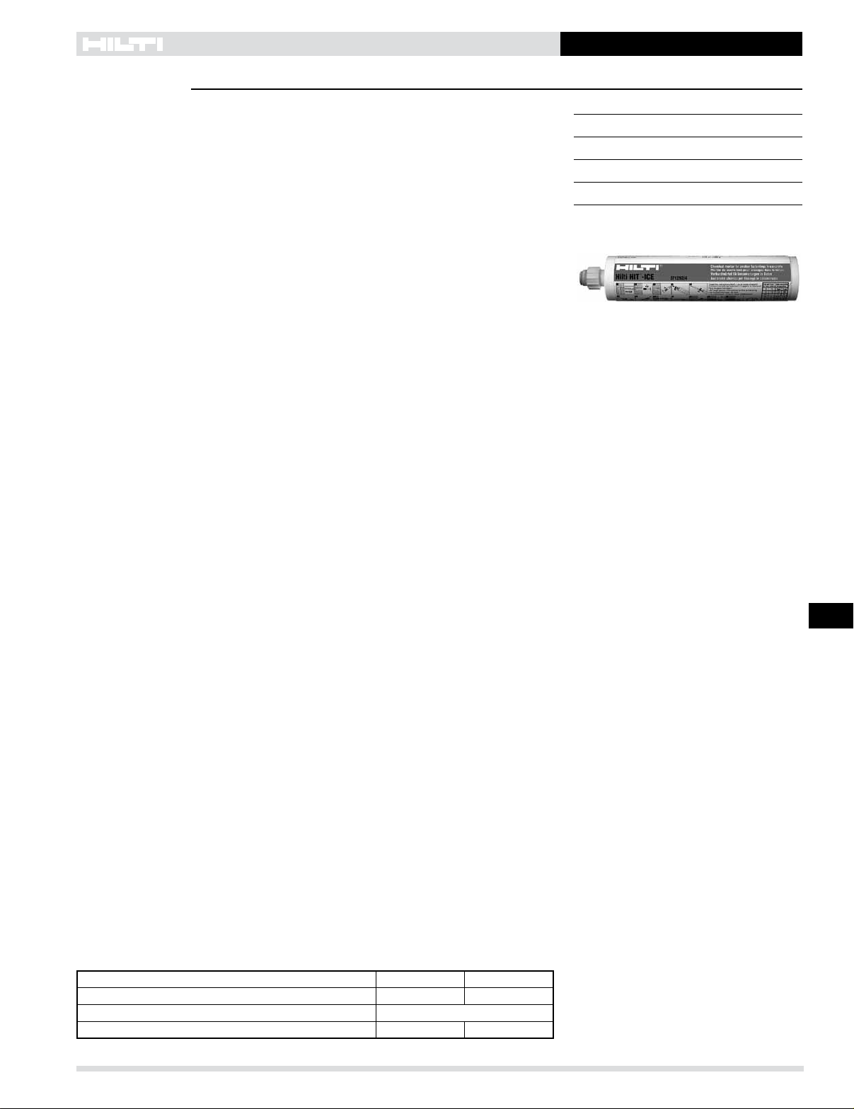
HIT-ICE Adhesive Anchoring System 3.2.5
3.2.5
Hilti, Inc. (US) 1-800-879-8000 | www.us.hilti.com I en español 1-800-879-5000 I Hilti (Canada) Corp. 1-800-363-4458 I www.hilti.ca I Anchor Fastening Technical Guide 2016 203
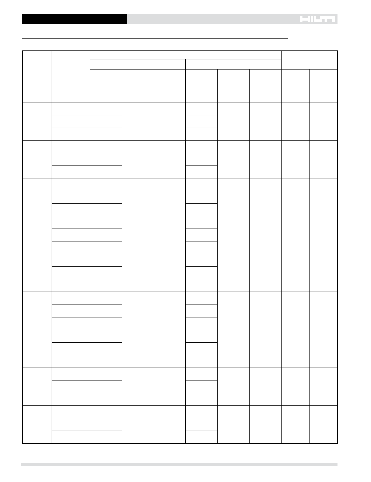
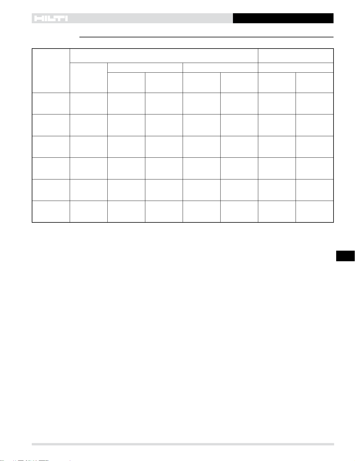
Table 6 - HIT-ICE allowable and ultimate bond/concrete capacity for HIT-V/HAS rods in normal-weight concrete1,2
Nominal
anchor
diameter
in.
Effective
embedment
in. (mm)
HIT-ICE
allowable bond/concrete capacity
HIT-ICE
ultimate bond/concrete capacity
Tensile Shear Tensile Shear
ƒ'c = 2,000 psi
(13.8 MPa)
lb (kN)
ƒ'c = 4,000 psi
(27.6 MPa)
lb (kN)
ƒ'c = 2,000 psi
(13.8 MPa)
lb (kN)
ƒ'c = 4,000 psi
(27.6 MPa)
lb (kN)
ƒ'c = 2,000 psi
(13.8 MPa)
lb (kN)
ƒ'c = 4,000 psi
(27.6 MPa)
lb (kN)
ƒ'c = 2,000 psi
(13.8 MPa)
lb (kN)
ƒ'c = 4,000 psi
(27.6 MPa)
lb (kN)
3/8
1-3/4 720 1,265 1,395 1,970 2,710 4,750 4,175 5,900
(44) (3.2) (5.6) (6.2) (8.8) (12.1) (21.1) (18.6) (26.2)
3-1/2 1,895 2,705 3,335 4,715 7,120 10,160 10,000 14,140
(89) (8.4) (12.0) (14.8) (21.0) (31.7) (45.2) (44.5) (62.9)
5-1/4 2,635 2,800 6,120 8,655 9,880 10,510 18,360 25,960
(133) (11.7) (12.5) (27.2) (38.5) (44.0) (46.8) (81.7) (115.5)
1/2
2-1/8 1,220 1,575 1,980 2,800 4,580 5,910 5,940 8,400
(54) (5.4) (7.0) (8.8) (12.5) (20.4) (26.3) (26.4) (37.4)
4-1/4 2,725 3,935 5,150 7,280 10,220 14,760 15,440 21,840
(108) (12.1) (17.5) (22.9) (32.4) (44.5) (65.7) (68.7) (97.1)
6-3/8 4,300 5,295 9,455 13,375 16,140 19,860 28,360 40,120
(162) (19.1) (23.6) (42.1) (59.5) (71.8) (88.3) (126.2) (178.5)
5/8
2-1/2 1,620 1,985 2,460 3,480 6,090 7,460 7,380 10,440
(64) (7.2) (8.8) (10.9) (15.5) (27.1) (33.2) (32.8) (46.4)
5 4,395 5,250 7,350 10,390 16,480 19,690 22,040 31,160
(127) (19.5) (23.4) (32.7) (46.2) (73.3) (87.6) (98.0) (138.6)
7-1/2 6,025 8,225 13,495 19,080 22,595 30,850 40,480 57,240
(191) (26.8) (36.6) (60.0) (84.9) (100.5) (137.2) (180.0) (254.6)
3/4
3-3/8 2,365 3,925 5,435 7,680 8,870 14,720 16,295 23,040
(86) (10.5) (17.5) (24.2) (34.2) (39.5) (65.5) (72.5) (102.5)
6-5/8 4,655 8,885 12,270 17,355 17,460 33,330 36,800 52,060
(168) (20.7) (39.5) (54.6) (77.2) (77.7) (148.3) (163.7) (231.6)
10 9,515 12,140 22,755 32,180 35,695 45,530 68,260 96,540
(254) (42.3) (54.0) (101.2) (143.1) (158.8) (202.5) (303.6) (429.4)
7/8
3-3/4 3,080 4,800 6,705 9,480 11,555 18,000 20,105 28,430
(95) (13.7) (21.4) (29.8) (42.4) (51.4) (80.1) (89.4) (126.5)
7-1/2 7,845 11,020 15,960 22,575 29,430 41,000 47,880 67,720
(191) (34.9) (49.0) (71.0) (100.4) (130.9) (182.3) (213.0) (301.2)
11-1/4 13,330 16,645 29,330 41,475 49,990 62,425 87,980 12,4420
(286) (59.3) (74.0) (130.5) (184.5) (222.4) (277.7) (391.4) (553.4)
1
4-1/8 3,445 4,865 8,265 11,685 12,920 18,250 24,790 35,050
(105) (15.3) (21.6) (36.8) (52.0) (57.5) (81.2) (110.3) (155.9)
8-1/4 8,330 11,635 19,690 27,840 31,250 43,640 59,060 83,520
(210) (37.1) (51.8) (87.6) (123.8) (139.0) (194.1) (262.7) (371.5)
12-3/8 15540 19,525 36,170 51,150 58,280 73,220 108,500 153,440
(314) (69.1) (86.8) (160.9) (227.5) (259.3) (325.7) (482.6) (682.5)
1-1/4
6 4645 7,000 14,760 20,870 17,430 26,265 44,280 62,610
(152) (20.7) (31.1) (65.7) (92.8) (77.5) (116.8) (197.0) (278.5)
12 15,490 20,770 38,615 54,610 58,085 77,900 115,840 163,820
(305) (68.9) (92.4) (171.8) (242.9) (258.4) (346.5) (515.3) (728.7)
15 19,210 26,815 53,960 76,315 72,040 100,560 161,880 228,940
(381) (85.5) (119.3) (240.0) (339.5) (320.5) (447.3) (720.1) (1018.4)
1Influence factors for spacing and/or edge distance are applied to concrete/bond values above, and then compared to the steel value. The
lesser of the values is to be used for the design.
2 For hef≥hef,stdaverageultimateconcreteshearcapacitybasedonStrengthDesignmethod.Forhef < hef,std average ultimate concrete shear
values based on testing.