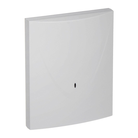
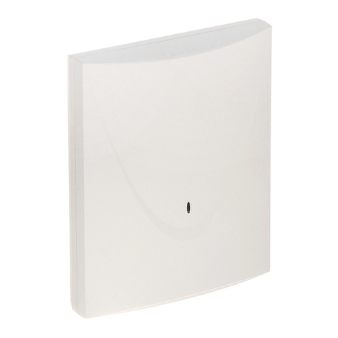
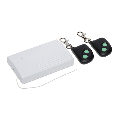
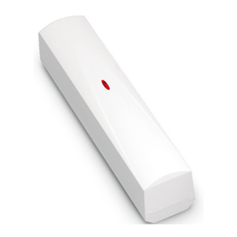
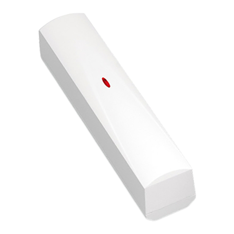
Satel MICRA VERSA-MCU User manual

VERSA-MCU
MICRA wireless system controller
Firmware version 1.04 versa-mcu_en 06/20
SATEL sp. z o.o. •ul. Budowlanych 66 • 80-298 Gdańsk • POLAND
tel. +48 58 320 94 00
www.satel.eu

IMPORTANT
The device should be installed by qualified personnel.
Prior to installation, please read carefully this manual in order to avoid mistakes that can lead
to malfunction or even damage to the equipment.
Disconnect power before making any electrical connections.
Changes, modifications or repairs not authorized by the manufacturer shall void your rights
under the warranty.
SATEL aims to continually improve the quality of its products, which may result in changes in
their technical specifications and software. Current information about the changes being
introduced is available on our website.
Please visit us at:
http://www.satel.eu
Hereby, SATEL sp. z o.o. declares that the radio equipment type VERSA-MCU is in
compliance with Directive 2014/53/EU. The full text of the EU declaration of conformity
is available at the following internet address: www.satel.eu/ce
The following symbols may be used in this manual:
- note,
- caution.

CONTENTS
1. Features............................................................................................................................2
2. Specifications....................................................................................................................2
3. Electronics board ..............................................................................................................3
4. Installation.........................................................................................................................4
4.1 Selecting a mounting location.....................................................................................4
4.2 Preparing the cabling..................................................................................................4
4.3 Installation of enclosure..............................................................................................4
4.4 Connecting the wires..................................................................................................5
4.5 Start-up.......................................................................................................................5
5. MICRA wireless detectors.................................................................................................6
5.1 Adding a detector........................................................................................................6
5.1.1 DLOADX program................................................................................................6
5.1.2 LCD keypad .........................................................................................................7
5.2 Removing a detector...................................................................................................7
5.2.1 DLOADX program................................................................................................7
5.2.2 LCD keypad .........................................................................................................8
6. 433 MHz keyfobs ..............................................................................................................8
6.1 Adding a keyfob..........................................................................................................8
6.1.1 DLOADX program................................................................................................8
6.1.2 LCD keypad .........................................................................................................9
6.2 Removing a keyfob.....................................................................................................9
6.2.1 DLOADX program................................................................................................9
6.2.2 LCD keypad .........................................................................................................9
7. MRU-300 radio signal repeater .......................................................................................10
8. Controller firmware update..............................................................................................10

2 VERSA-MCU SATEL
The VERSA-MCU controller enables:
installation of MICRA wireless detectors in the alarm system,
control of the alarm system by means of 433 MHz keyfobs.
The controller works with the VERSA series control panels:
VERSA 5 / VERSA 10 / VERSA 15 (firmware version 1.03 or newer),
VERSA IP,
VERSA Plus,
VERSA Plus LTE.
1. Features
High-sensitivity 433 MHz superheterodyne radio receiver immune to spurious signals.
Support for up to 30 MICRA wireless detectors:
–encrypted transmissions,
–capability to control the presence of the detectors.
Support for up to 30 SATEL 433 MHz keyfobs:
–transmissions encrypted using code-hopping,
–capability to run up to 6 functions with the keyfob.
Support for MRU-300 radio signal repeater.
Controller firmware update capability.
Tamper protection against enclosure opening and removal from mounting surface.
2. Specifications
Operating frequency band............................................................... 433.05 MHz ÷434.79 MHz
Supply voltage ....................................................................................................12 VDC
±
15%
Standby current consumption ..........................................................................................24 mA
Maximum current consumption........................................................................................29 mA
Number of supported wireless detectors................................................................................30
Number of supported keyfobs................................................................................................30
Environmental class according to EN50130-5 .........................................................................II
Operating temperature range...............................................................................-10°C...+55°C
Maximum humidity..........................................................................................................93
±
3%
Enclosure dimensions................................................................................... 26 x 112 x 29 mm
Weight.................................................................................................................................30 g

SATEL VERSA-MCU 3
3. Electronics board
terminals:
+12V - power input.
COM - common ground.
CLK - communication bus clock.
DAT - communication bus data.
RS-232 (TTL) port. Used for updating the controller firmware (see “Controller firmware
update” p. 10).
tamper switch.
LED indicating the status of communication with the control panel:
ON –no communication with the control panel,
flashing –communication with the control panel OK.
DIP-switch (not used).
superheterodyne receiver.
antenna.

4 VERSA-MCU SATEL
4. Installation
Disconnect power before making any electrical connections.
4.1 Selecting a mounting location
The controller should be installed indoors, in spaces with normal air humidity.
Prior to installation you should plan the arrangement of all MICRA wireless detectors which
are to be supported by the controller. The controller should be mounted at a location within
the range of wireless detectors (or within the range of the MRU-300 repeater if it is to be
installed in the system). Remember that thick walls, metal partitions, etc. will reduce the
range of the radio signal.
It is recommended that the controller be mounted high above the floor. This will allow you to
get a better range of radio communication and avoid the risk of the controller being
accidentally covered by people moving around the premises.
Installing the device in close vicinity of electrical systems is not recommended, since it can
adversely affect the range of radio signal.
4.2 Preparing the cabling
Prepare the power cables and the cables you will use to connect the controller to the control
panel and run them to the controller’s installation location. Use an unshielded non-twisted
cable. If you use the twisted-pair type of cable, remember that CLK (clock) and DAT (data)
signals must not be sent through one pair of twisted conductors. For power cables, use
flexible conductors with cross-sectional area of 0.5-0.75 mm2.
The cabling should not be run in close vicinity of low-voltage electrical system wires, and
especially of power cables for high-power equipment (such as electric motors).
4.3 Installation of enclosure
1. Open the controller enclosure (Fig. 2).
2. Place the enclosure base against the wall and mark location of the mounting holes.
3. Drill holes for wall plugs (anchors) in the wall.
4. Make the cable entry opening at the base. The opening diameter must be larger than
5 mm. The finished opening must not have sharp edges.
5. Run the wires through the prepared opening (power cables and cables connecting the
controller with the control panel).
6. Using wall plugs and screws, secure the enclosure base to the wall (Fig. 3). The wall
plugs delivered with the device are intended for concrete, brick, etc. For other types of
surface (drywall, styrofoam), use the appropriately selected wall plugs.
SATEL VERSA-MCU 5
4.4 Connecting the wires
1. Connect the CLK, DAT and COM terminals to the corresponding terminals of the control
panel communication bus (Fig. 4).
2. Connect the power wires to the +12V and COM terminals. If the distance to the control
panel is less than 300 meters, the controller can be supplied directly from the control
panel (Fig. 4). If the distance to the control panel is higher, the controller must be supplied
from another power source, which is located at a closer distance (a power supply or
an expander with power supply).
4.5 Start-up
1. Close the enclosure.
2. Power up the controller.

6 VERSA-MCU SATEL
3. Start the identification function in the control panel (see the control panel installer
manual). The controller will be identified as two devices: INT-RX (address 7) and
VERSA-MCU (address 8).
5. MICRA wireless detectors
The controller supports the following MICRA (433 MHz) wireless detectors:
MFD-300 –wireless water flood detector.
MGD-300 –wireless glass-break detector.
MMD-300 –wireless magnetic contact.
MMD-302 –wireless magnetic contact with input for roller shutter detector.
MPD-300 –wireless passive infrared detector.
MPD-310 –wireless passive infrared detector.
MPD-310 Pet –wireless passive infrared detector with pet immunity up to 20 kg.
MSD-300 –wireless smoke and heat detector.
MSD-350 –wireless smoke detector.
MXD-300 –wireless multipurpose detector.
For information about installation of individual detectors, please refer to their manuals.
A wireless detector must be registered to the controller. You can do so by using the DLOADX
program or LCD keypad. When adding (registering) a detector, you must enter its serial
number. The location of the serial number sticker is indicated in the detector manual.
The data on wireless detectors are stored in the controller. If you connect to the control
panel a controller with registered detectors, during identification procedure, these
detectors will be automatically assigned to the system zones.
5.1 Adding a detector
5.1.1 DLOADX program
1. Open the “VERSA – Structure” window.
2. Click on the “Hardware” tab.
3. Click on the name of the VERSA-MCU controller on the device list.
4. Click on the “Read” button to read the detector data from the controller (these data are not
read after clicking on the button in the main menu).
5. Click on the zone to which you want to assign a new detector (you can also select the
zone later in the “New wireless dev.” window).
6. Click on the “New device” button. The “New wireless dev.” window will open.
7. Enter the serial number of the detector being added in the “Serial number” field.
8. Open the detector tamper switch.
9. A message will confirm that the detector has been added (unless you have entered an
invalid serial number, of which the message will inform you).
9.1. Detector type will be displayed.
9.2. A new name of the zone to which the detector is to be assigned will be displayed.
You can change the name.

SATEL VERSA-MCU 7
9.3. In the “Zone” field, select the number of the zone to which you want to assign the
detector (if you have not done this before or if you want to change the previously
selected number).
10.Click on the “OK” button. The “New wireless dev.” window will close. The new detector will
be displayed on the list of detectors.
11.Click on the “Write” button to save changes to the controller (wireless detector data are
not saved after clicking on the button in the main menu).
5.1.2 LCD keypad
1. Start the service mode.
2. Start the “New device” function (“2.Hardware” “1.Kpds. & exps” “3.Wireless dev.”
“1.New device”).
3. When the “Serial number” is displayed, enter the serial number of the detector being
added.
4. Press .
5. When the “Open device tamper” command is displayed, open the detector tamper switch.
6. When the type and serial number of the detector will be displayed, press (if nothing
happens, you might have entered a wrong serial number –press to quit the
function).
7. Use the and keys to select the zone to which you want to assign the
detectors.
8. Press .
9. The new name of the zone to which the detector has been assigned will be displayed.
You can change that name.
10.Press .
11.The “Presence control” option will be displayed. By default, the option is enabled (the
symbol is displayed). If you want to disable the option, press any number key (the
symbol will be displayed).
12.Press .
5.2 Removing a detector
5.2.1 DLOADX program
1. Open the “VERSA – Structure” window.
2. Click on the “Hardware” tab.
3. Click on the name of the VERSA-MCU controller on the device list.
4. Click on the “Read” button to read the detector data from the controller (these data are not
read after clicking on the button in the main menu).
5. Click on the detector you want to remove.
6. Click on the “Delete” button. The “Confirm” window will open.
7. Click on the “Yes” button. The “Confirm” window will close.
8. Click on the “Write” button to save changes to the controller (wireless detector data are
not saved after clicking on the button in the main menu).

8 VERSA-MCU SATEL
5.2.2 LCD keypad
1. Start the service mode.
2. Start the “Remove device” function (“2.Hardware” “1.Kpds. & exps” “3.Wireless
dev.” “3.Remove device”). List of wireless zones will be displayed.
3. Use the and keys to select the zone to which the detector you want to
remove is assigned.
4. Press .
5. When a prompt will be displayed asking you whether to remove the detector (type and
serial number of the detector will be displayed), press .
6. 433 MHz keyfobs
The controller supports the following SATEL 433 MHz keyfobs:
MPT-350 –5-button keyfob,
MPT-300 –5-button keyfob,
T-4 –4-button keyfob,
T-2 –2-button keyfob,
T-1 –1-button keyfob,
P-4 –4-button keyfob,
P-2 –2-button keyfob.
A keyfob must be registered to the controller. You can do so by using the DLOADX program
or LCD keypad. When adding (registering) a detector, its serial number will be required.
You will find it on the keyfob’s bag.
The data on keyfobs are stored in the controller. If you connect to the control panel
a controller with registered keyfobs, these keyfobs will be automatically assigned to
the existing users.
For a list of functions that can be started by means of keyfobs, please refer to manuals for
the VERSA series control panels.
6.1 Adding a keyfob
6.1.1 DLOADX program
1. Open the “VERSA – Structure” window.
2. Click on the “Hardware” tab.
3. Click on the name of the INT-RX expansion module on the device list.
4. Click on the “Read” button to read the keyfob data from the controller (these data are not
read after clicking on the button in the main menu).
5. Use the procedure of reading the serial number during transmission or enter the serial
number manually (both procedures are described below).
6. Assign the functions to the keyfob buttons (the procedure is described below).
7. Click on the “Write” button to save changes to the controller (keyfob data are not saved
after clicking on the button in the main menu).

SATEL VERSA-MCU 9
Reading the serial number during transmission
1. Click on the field in the "S/N" column next to the name of the user to whom you want to
add a keyfob.
2. Click on the “New” button. The “New” window will open.
3. Press the keyfob button. The keyfob serial number will be displayed.
4. Click on the “OK” button. The “New” window will close. The serial number of the new
keyfob will be shown in the “S/N” column.
Entering the serial number manually
1. Click on the field in the "S/N" column next to the name of the user to whom you want to
add a keyfob.
2. Enter the keyfob serial number and press ENTER.
Assigning a function to the keyfob button (combination of buttons)
After adding a keyfob, the functions provided for by the user schedule will be assigned to the
buttons. You can replace them with others.
1. Right click on the field corresponding to the button (combination of buttons). The list of
functions will be displayed.
2. Click on the function to be run by the keyfob button (combination of buttons).
6.1.2 LCD keypad
You can add a keyfob during the adding a user / user editing procedure. You will find the
procedure described in user manuals for the VERSA series control panels.
6.2 Removing a keyfob
Removing a keyfob only clears its serial number, but not its settings. If a new keyfob is
added to the user, it will have the same settings as the removed one.
You can remove all keyfobs and their settings using the “Rem.RX k-fobs” function
available in the service mode in the keypad (“2.Hardware” “1.Kpds. & exps.”
“9.Rem.RX k-fobs”).
6.2.1 DLOADX program
1. Open the “VERSA – Structure” window.
2. Click on the “Hardware” tab.
3. Click on the name of the INT-RX expansion module on the device list.
4. Click on the “Read” button to read the keyfob data from the controller (these data are not
read after clicking on the button in the main menu).
5. Click on the serial number of the keyfob you want to remove.
6. Click on the “Delete” button. The “Confirm” window will open.
7. Click on the “Yes” button. The “Confirm” window will close.
8. Click on the “Write” button to save changes to the controller (keyfob data are not saved
after clicking on the button in the main menu).
6.2.2 LCD keypad
You can remove a keyfob during the adding a user / user editing procedure. You will find the
procedure described in user manuals for the VERSA series control panels.

10 VERSA-MCU SATEL
7. MRU-300 radio signal repeater
For information about installation of the MRU-300 repeater, please refer to its manual.
If you want to register the repeater to the controller, proceed in the same way as when
adding a wireless detector (see “Adding a detector” p. 6). The repeater will be identified as
the MMD-300 detector.
You do not have to register the repeater in the controller but its operation will not be
supervised if unregistered (power failures, lack of presence or tamper will not be
reported).
Information about low battery should be interpreted as AC power supply loss.
8. Controller firmware update
1. Connect the controller with the computer using the SATEL USB-RS converter.
2. Download the controller firmware update program from www.satel.eu.
3. Launch the downloaded program.
4. Click on the button.
5. In the window that will open, indicate the COM port to which the controller is connected,
and then click “OK”.
6. Restart the controller (power down and power up).
7. The program will read information on the installed firmware version from the controller.
8. When the prompt is displayed asking you whether to continue the firmware update, click
“Yes”.
9. The controller firmware will be updated.
Other manuals for MICRA VERSA-MCU
1
Table of contents
Other Satel Controllers manuals

Satel
Satel KNX-BSA12L User manual

Satel
Satel ASW-100 E User manual

Satel
Satel KNX-BSA12H User manual

Satel
Satel RX1K User manual

Satel
Satel ACU-250 User guide

Satel
Satel Abax ACU-100 User manual

Satel
Satel KNX-DIM21 User manual

Satel
Satel KNX-SA41 User manual

Satel
Satel ACU-220 User manual

Satel
Satel MICRA VERSA-MCU User manual

Satel
Satel VERSA-MCU User manual

Satel
Satel RX-2K User manual

Satel
Satel ABAX 2 ACU-280 User manual

Satel
Satel ACU-120 User manual

Satel
Satel ACU-280 User manual

Satel
Satel ACU-280 User manual

Satel
Satel INT-CR User manual

Satel
Satel ASW-210 User manual

Satel
Satel ABAX 2 ACU-220 User manual

Satel
Satel KNX-SA41 User manual