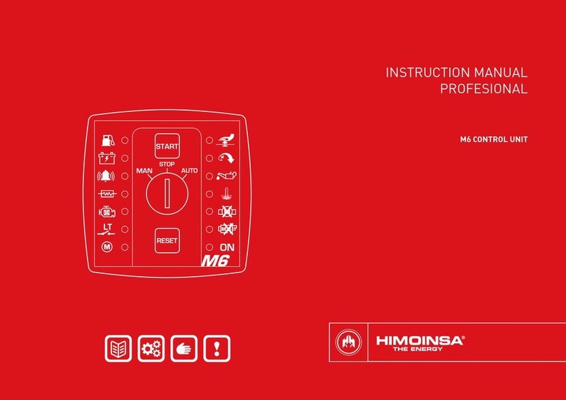
Himoinsa M1 User manual

INSTRUCTION MANUAL
PROFESSIONAL
M1 CONTROL UNIT

| PAGE 2
INDEX
3 1. Description and general characteristics
5 2. Front panel components
7 3. Components at the rear
14 4. Operating modes
16 5. Dimensions, wiring and mechanical parts
19 6. Table of parameters
19 7. Most notable advantages

DESCRIPTION AND GENERAL CHARACTERISTICS | PAGE 3
1. DESCRIPTION AND GENERAL
CHARACTERISTICS
The control panel and the protection are presented in a 66 x 66 x 85 mm box for
panel mounting. Manufactured in aluminium and reproof polyamide 6 (Class
V0), its colour is black.
It incorporates the possibility of starting the engine manually or automatically
(through free voltage contact) and of protecting it against any malfunctions while
it is running. This is managed by an electronic circuit based on a microcontroller,
which is located inside the control unit.
At the front, there is a button to turn the control unit on or off, a reset button, a
knob to select MANUAL, STOP or AUTOMATIC mode, and 14 indicator lights. At
the back there are: 19 plug-in connection terminals divided into three blocks, a
USB port for programming and consulting the alarms log and the hour metres,
plus 8 micro switches with which to congure the operation.
The general characteristics are as described below:
1. Supply voltage 8/36V
2. Start-up by free voltage contact (LT)
3. Engine protection devices:
•Fuel reserve
•Battery charging failure
•High engine coolant temperature
•Low oil pressure
4. Protection against over-frequency (overspeeding):
•By generator set
•By Pick-Up
5. Auxiliary input with alarm indicator light
6. All outputs can be short circuited
7. Quick connect terminals

DESCRIPTION AND GENERAL CHARACTERISTICS | PAGE 4
8. A USB port that makes it possible to:
•Read the internal hour metre
•Dump the alarms log
•Communicate with a PC
•Advanced programming of the parameters of the control unit. Of
which the most important are:
- Programming and activation of overspeed
- Ability to read the frequency by generator set or Pick-Up
- Preheating time
- Cooling down time
- Action after fuel reserve alarm
- Detection of engine started by D+
- Detection of engine stopped by BPA

FRONT PANEL COMPONENTS | PAGE 5
2. FRONT PANEL COMPONENTS
The control unit acts as protection of a diesel engine with the possibility of carry-
ing out the start-up manoeuvre. Note the following elements at the front:
Start/Stop button. This allows you to start and stop the
engine when you have selected the manual mode.
Mode Selection Knob (MAN STOP AUT). In the "MAN”
position, the control unit will give the direct order to start up
(performing 1 start-up attempt). In the "STOP" position, the
control unit will order the genset to stop. In the "AUT”
position, the control unit will stay in automatic mode and will
operate as follows: if the "LT" earth contact is closed, the
control unit will order it to start up and if the contact is
opened, it will order it to stop.
RESET button. This allows you to restart the control unit’s
operation cycle and delete alarm notications. If you hold the
reset button for ve seconds, with the engine running, it
memorizes the engine speed and it activates the overspeed
control. If you press and hold it for ve seconds with the
engine turned off, the overspeed control is disabled.

FRONT PANEL COMPONENTS | PAGE 6
Low oil pressure LED. This indicates that the engine’s
pressure switch has detected an abnormality. This protection
activates a timed shutdown cycle. The LED will remain lit while
the alarm condition persists and until the control unit is reset.
High water temperature LED. This indicates that the engine’s
thermostat has detected an abnormality in the running
temperature. This signal activates a timed shutdown cycle of
the genset. The LED will remain lit while the alarm condition
persists and until the control unit is reset.
Engine failure LED. This indicates that the engine has
stopped without the control unit having ordered it to stop.
Start-up failure LED. This indicates that after having made the
congured attempts to start the engine, the control unit has
failed to start it up.
Power supply. This optical signal indicates that the control
unit is turned on.
Fuel reserve LED. Indicates low level of fuel in the tank. This
indicator remains lit as long as the alarm condition persists.
Battery charging failure LED. This indicates that the battery
charge generator is not charging the battery. This indicator
remains lit as long as the alarm situation persists.
AUXILIARY alarm LED. This indicates that the alarm condition
established for the control unit’s auxiliary input has been
detected. This indicator remains lit as long as the alarm
situation persists.
PREHEATING LED. This indicator starts ashing at intervals of
approximately one second, during the preheating cycle
performed before each attempt to start the engine.
COOL STOP LED. This indicator starts ashing at intervals of
about one second when the control unit orders a shutdown
cycle. It does not turn off until the cycle comes to an end.
"LT" contact enabled LED. This signal is activated when the
free voltage contact is closed to earth and it turns off when it
is opened.
Engine running LED. This indicates that the engine is running.
The detection can be performed either by reading the D+ or by
reading the frequency. This latter can be done by generator
set or by Pick-Up.
EMERGENCY STOP LED. This indicator is activated when you
press the genset’s emergency stop. After the alarm condition,
it only turns off once the emergency stop has been rearmed
and the control unit has been reset.
OVERSPEEDING LED. This LED is activated by two conditions:
when the overspeed condition is not activated (see paragraph
3.2) and when the internal overspeed protection device turns
on. In the latter case, the control unit activates a timed
shutdown cycle and the optical indication will persist until you
reset the control unit.

COMPONENTS AT THE REAR | PAGE 7
3. COMPONENTS AT THE REAR
The rear is where the connection terminals are found, together with a USB port
for programming parameters, consulting the alarms log and the total and partial
hour meter.
CONNECTION TERMINALS
1. Alternator voltage input 220V (GEN)
2. Pick-up input (PCK)
3. Pick-up and alternator voltage common input (GCOM)
4. Water temperature input (ATA)
5. Low oil pressure input (BPA)
6. Fuel reserve input (RC)
7. Auxiliary input (AUX)
8. External start input (LT)
9. Emergency stop input (PEM)
10. Preheating output (PR)
11. Contactor activation output (CON)
12. D+ terminal (D+)
13. Alarm output (AL)
14. Battery negative (-BAT)
15. Battery positive 12/24 (8-36V)
16. Starting output (ARR)
17. Stop by excitation (PC)
18. Stop by de-excitation (PD)
19. Power supply for power outlets (+BAT)

COMPONENTS AT THE REAR | PAGE 8
3.1.3 D+ TERMINAL (D+) (12)
The D+ terminal of the generator set’s battery charging alternator is connected to
this output to excite it and to begin charging the battery. Moreover, internally, the
control unit reads the battery charging voltage, which makes it possible both to
detect whether there has been a failure of the charging alternator and if the en-
gine has started.
3.1.4 ALARM OUTPUT (AL) (13)
The output associated with this terminal is activated when it detects any abnor-
mality in the functioning of the genset or there are values outside the set range.
3.1.5 BATTERY NEGATIVE (-BAT) (14)
The battery negative is connected to this terminal.
3.1.6 BATTERY POSITIVE (8-36V) (15)
The battery positive is connected to this terminal, whether it be 12V or 24V.
3.1.7 START-UP OUTPUT (ARR) (16)
When the engine is ordered internally to start up, this output is activated during
the set time, thereby supplying the starter motor with power. If it detects that the
engine is running, it stops activating this output.
3.1.8 CONFIGURABLE STOP (PC) (17)
This output can act as a stop by excitation or as a stop by de-excitation, depend-
ing on the engine type selected in the conguration (see section 3.2). In engines
with stop by excitation, when the generator set is ordered internally to stop, this
output is activated during the set time. If after this time it detects that the genset
has not stopped, it will continue ordering it to stop for successive periods of the
same duration, until it does stop. In engines with stop by de-excitation, the out-
put is deactivated to perform the stop.
USB PORT
This allows you to use a PC to perform the programming of certain parameters, in
addition to reading the internal hour meter (full and partial) and the alarm log.
CONFIGURATION MICRO SWITCHES
This allows you to congure the behaviour of the control unit manually, without
resorting to a PC, by selecting ON/OFF on the micro switches.
•Long preheating
•Frequency detection by PICK-UP
•Engine shutdown by FR (Fuel Reserve)
•Preheating enabling
•Cooling enabling
•Detection of start-up by D+
•Engine conguration (MSB bit)
•Engine conguration (LSB bit)
3.1 CONNECTION TERMINALS
One of the main features of the M1 control unit's wiring connections that is
worth mentioning is the fact that these are made using quick connect terminals.
A brief description of each one of them follows below:
3.1.1 PREHEATING OUTPUT (PR) (10)
The output associated with this terminal is activated before each start-up at-
tempt, during the pre-set time in line with the corresponding parameter (see the
table of parameters), in order to preheat the engine.
3.1.2 CONTACTOR ACTIVATION OUTPUT (CON) (11)
The output associated with this terminal is activated after the heating time
(20 secs), once the control unit has detected that the engine has started. It is
used so that the genset heats up in a vacuum before the contactor that will start
to charge it is activated.

COMPONENTS AT THE REAR | PAGE 9
3.1.13 WATER TEMPERATURE INPUT (ATA) (4)
This is a digital input that is activated at low level. It is connected to the thermo-
stat of the engine coolant temperature and it activates the high-water -tempera-
ture alarm.
3.1.14 LOW OIL PRESSURE INPUT (BPA) (5)
This is a digital input that is activated at low level. It is connected to the pressure
switch of the engine oil pressure and it activates the low-oil-pressure alarm.
3.1.15 FUEL RESERVE INPUT (RC) (6)
This is a digital input that is activated at low level. It is connected to the ume of
the fuel tank and it activates the reserve fuel alarm. The action that should be
taken after the alarm is detected can be programmed (see section 3.2).
3.1.16 AUXILIARY INPUT (AUX) (7)
This is a digital input that is activated at low level. You can connect any type of
sensor that closes a contact when it is activated. It emits a visual signal through
the yellow AUXILIARY (AUX) alarm LED.
3.1.17 EXTERNAL START-UP INPUT (LT) (8)
This is a digital input that is activated at low level. It is connected to a free volt-
age contact (LT) which is used to order the start-up sequence of the generator
set when the control unit is in automatic mode (see section 4.2).
3.1.18 EMERGENCY STOP INPUT (PEM) (9)
If this input is activated, it stops the generator set immediately. This terminal is
connected to negative through an emergency button with an NC (Normally Closed)
contact. To activate this input, the contact has to be opened. When it has been
opened, there is no longer a negative in the control unit input.
3.1.9 STOP BY DE-EXCITATION (PD) (18)
The output associated with this terminal is activated when the genset must be
started and it is deactivated when the control unit orders it to stop.
3.1.10 ALTERNATOR VOLTAGE INPUT (GEN) (1)
This input is used to read the frequency by generator set. To do so, one of the
phases of the generator set is connected to this terminal, while the neutral is
connected to the GCOM terminal. The reading is always performed between
phase and neutral, never between phases. The typical effective voltage for this
input is 220V; it is possible to reach a maximum effective value of 280V.
3.1.11 PICK-UP INPUT (PCK) (2)
This input is used to read the frequency by Pick-Up. To do so, one of the cables is
connected to this terminal, with the signal provided by the magnetic Pick-Up,
while the other one is connected to the GCOM terminal of the control unit. These
inputs have no polarity.
3.1.12 COMMON VOLTAGE INPUT OF THE ALTERNATOR AND PICK-UP (GCOM) (3)
This input is common and is used to connect the neutral of the generator set, if
the frequency reading is performed by generator set, and one of the signal leads
of the Pick-Up, if the reading is performed using this type of sensor.
You can only use one of the two types of frequency readings, never both of them
at the same time. Use the conguration software to choose between the two
reading methods.
NOTE
It is very important to connect only one of the two frequency reading inputs. In
other words, if you connect the phase and the neutral of the alternator to the
generator’s control unit input, you cannot connect the wires of the Pick-Up to the
corresponding input and vice versa.

COMPONENTS AT THE REAR | PAGE 10
3.2.7 STOP TIME
Maximum time (in seconds) of the stop by excitation (stop electromagnet). Once
it detects that the engine has stopped, the stop by excitation output is
deactivated.
3.2.8 LOW OIL PRESSURE DELAY
Time, from start-up, until the low oil pressure alarm is taken into account.
3.2.9 HIGH WATER TEMPERATURE DELAY
Time, from start-up, until the low water pressure alarm is taken into account.
3.2.10 AUXILIARY INPUT DELAY
Time, from start-up, until the auxiliary input alarm is taken into account.
If you select delay time equal to zero the auxiliary input is always evaluated, even
when the engine is not running.
NOTE
For engines with stop by excitation congured as PR/PE in which the emergency
stop disables by hardware the use of a PC used as PE. The emergency pushbut-
ton has to be wired to the AUX input rather than to the PEM so that the PC
output is not disabled and can perform the stop by excitation. In this case you
must set the delay to 0 so that the input is always checked. This problem does
not exist for the PE/PD conguration, and you may wire the emergency pushbut-
ton to the PEM input.
3.2.11 FREQUENCY THRESHOLD FOR DETECTING START-UP
Percentage of the scheduled frequency as of which the engine will be considered
started. The engine-running LED will come on when the engine is put in motion
but the genset will not consider that it has started until it exceeds this threshold.
3.2 PROGRAMMING BY USB
By connecting a USB and the conguration software, you can program some of
the control unit’s parameters as detailed below:
3.2.1 NUMBER OF START-UPS
Sets the number of start-up retries automatically performed by the control unit
before it signals a start-up failure.
3.2.2 TIME BETWEEN START-UPS
Time between starting retries (in seconds).
3.2.3 START-UP TIME
Maximum duration (in seconds) of the start-up signal if it detects that the genset
has not started up.
3.2.4 SPARK PLUG PREHEATING TIME
Duration of the spark plug preheating (default=0). This time is only applicable if
microswitch 4 is in the OFF position (preheating disabled). Otherwise, the times
set for microswitch 1 prevail (long/short preheating).
3.2.5 TIME FOR THE ACTIVATION OF THE GENSET’S BREAKER
Time from when it detects that the engine has started.
3.2.6 COOLING DOWN TIME
Time (in seconds) during which the engine will remain running to cool the unit,
after the genset’s breaker has been disabled, if cooling has been enabled (mi-
croswitch 5). To stop the genset and to skip the cooling time, simply press the
START button again while it is cooling.

COMPONENTS AT THE REAR | PAGE 11
3.2.16 FREQUENCY READING BY GENERATOR SET OT PICK-UP (GEN/PCK)
(READING ONLY. SELECTION BY MICROSWITCH 2)
Indicates whether the speed is controlled by generator set (microswitch 2 OFF) or
by the Pick-Up (microswitch 2 ON).
NOTE
It is very important to connect only one of the two frequency reading inputs. In
other words, if you connect the phase and the neutral of the alternator to the
generator’s control unit input, you cannot connect the wires of the Pick-Up to the
corresponding input and vice versa, under any circumstances.
3.2.17 ENABLING THE OVERSPEED THRESHOLD.
Enables or disables the overspeed control.
NOTE
When you disable the overspeed threshold, the stored rated frequency, if it
exists, will not be deleted and detection of start-up by frequency threshold will
continue to be enabled. If you want to delay the detection of start-up by speed,
you will have to increase the start-up detection frequency threshold.
3.2.18 ENGINE SHUTDOWN BY FUEL RESERVE (RC) - ALARM / SHUTDOWN
Allows you to select the action to be performed after the fuel reserve alarm has
been detected. If you select the "ON” option, when the alarm is detected, it acti-
vates the corresponding optical indicator and it starts a shutdown without cool-
ing cycle. In the "OFF" position, it only indicates the alarm by the optical signal
but it does not stop the group.
3.2.19 PREHEATING ENABLING (READING ONLY. SELECTION BY MICROSWITCH 4)
Enables or disables the preheating. If disabled (OFF), the duration of the preheat-
ing will be the "SPARK PLUG PREHEATING TIME” parameter, which by default is
zero. If it is enabled (ON), the preheating time is determined by microswitch 1
which chooses between short preheating (5 seconds) or a long one
(10 seconds).
If no rated frequency has been stored. The genset will be deemed to have start-
ed as of 20 Hz if the frequency reading by generator set option has been
selected.
3.2.12 THRESHOLD FOR OVER-FREQUENCY DETECTION
Percentage increase of the scheduled frequency above which it will be consid-
ered overspeeding.
3.2.13 ALARM OUTPUT ACTIVATION TIME
Indicates the time that the alarm output will be active. If it is set to zero, the out-
put will remain active indenitely until you press reset or you turn off the control
unit.
3.2.14 D+ TIME
Excitation time of the battery charging alternator (Always less than the starting
time).
3.2.15 ENGINE CONFIGURATION (READING ONLY. CONFIGURED BY
MICROSWITCHES 7 AND 8)
Engine (PR/PD) with preheating and stop by de-excitation provided through the
congurable stop output (Microswitch 7 OFF and Microswitch 8 OFF).
Engine (PR/PE) with preheating and stop by excitation at the congurable stop
output (Microswitch 7 OFF and Microswitch 8 ON).
Engine (PR/PE) with stop by excitation at the preheating output and stop by
de-excitation at the congurable stop output (Microswitch 7 ON and Microswitch
8 OFF).
Engine (PR/PULL) with preheating, PULL type start-up (1 press of 1 second) and
HOLD type stop provided through the PD Output (Microswitch 7 ON and Mi-
croswitch 8 ON).

COMPONENTS AT THE REAR | PAGE 12
3.2.23 POLARITY OF HIGH WATER TEMPERATURE INPUT (ATA)
NOTE
Some engines require special delays between the activation of the stop by
de-excitation signals and start-up and even though the preheating is disabled,
the control unit can perform delays of several seconds before start-up after
receiving the order to start up. If the application requires an immediate start-up
without preheating, disable the preheating and also set the preheating time to 0.
3.2.20 COOLING ENABLING (READING ONLY. SELECTION BY MICROSWITCH 5)
Enables or disables the cooling phase in the genset shutdown cycle.
3.2.21 DETECTION OF ENGINE STARTED BY BATTERY CHARGING ALTERNATOR (D+)
(READING ONLY. SELECTION BY MICROSWITCH 6)
If you disable detection by alternator battery charge (OFF), engine started detec-
tion should only be carried out by frequency reading (Generator set or Pick-Up).
NOTE
The engine started detection is always performed by frequency reading, whether
by Generator set or by Pick-Up. Activating this microswitch adds detection by D+,
in which case the engine started detection is performed simultaneously by
frequency reading and by D+. If no rated speed has been stored, the control unit
will consider that the genset has started when the frequency of the generator
set signal is greater than 20Hz, as long as frequency reading by generator set
has been selected.
3.2.22 DETECTION OF SHUTDOWN DUE TO LOW OIL PRESSURE
If this option is activated, the control unit will not consider that the engine has
stopped until the oil pressure has dropped. Until then it will not allow the engine
to be started up again.
3.2.24 POLARITY OF LOW OIL PRESSURE INPUT (BPA)
3.2.25 POLARITY OF AUXILIARY INPUT (AUX)
3.2.26 POLARITY OF FREE VOLTAGE INPUT (LT)
3.2.27 POLARITY OF RESERVE FUEL INPUT (RC)
The polarity of the inputs is congurable, which allows it to be activated at a high
or low level.
3.3 CONFIGURATION USING MICROSWITCHES
Allows you to modify the behaviour of the control unit using the microswitches, to
adapt to all types of units. By default, the control units come with the 8 mi
croswitches in the OFF position.
3.3.1 LONG PREHEATING (SW1)
The functionality of this microswitch is conditioned by the position of microswitch
4 (SW4) "Enabling Preheating".
SW1 SW4 Preheating
OFF OFF Preheating determined by parameter P4 "Preheating Time" (set to zero by
default).
ON OFF
OFF ON Short preheating (5 seconds)
ON ON Long preheating (10 seconds)
3.3.2 FREQUENCY DETECTION BY PICK-UP (SW2)
SW2 Operation
OFF Frequency detection by generator (GEN)
ON Frequency detection by PICK-UP (PCK)

COMPONENTS AT THE REAR | PAGE 13
SW7 SW8 Engine category PR output PC output
OFF OFF PR/PD Preheating Shutdown by De-excita-
tion
OFF ON PR/PE Preheating Shutdown by Excitation
ON OFF PE/PD Shutdown by Excitation Shutdown by De-excita-
tion
ON ON PR/PULL (Yanmar) Preheating Press 1 second
3.3.3 ENGINE SHUTDOWN BY FUEL RESERVE (SW3)
SW3 Operation
OFF If the fuel reserve signal goes off, it only signals an ALARM
ON If the fuel reserve signal goes off, it performs a SHUTDOWN without cooling the engine as
well as signalling the alarm.
3.3.4 PREHEATING ENABLING (SW4)
SW4 Preheating
OFF Determined by parameter P4 "Preheating Time" (set to zero by default).
ON Long or short preheating determined by SW1. See table 3.3.1
3.3.5 COOLING ENABLING (SW5)
SW5 Cool down
OFF The engine is shut down without cooling.
ON The engine is cooled as per the congured time.
3.3.6 DETECTION OF RUNNING ENGINE BY BATTERY CHARGING ALTERNATOR (D+)
SW6 Detection of running engine by battery charging alternator (D+)
OFF Disabled
ON Enabled
3.3.7 ENGINE TYPE CONFIGURATION (SW7 AND SW8)

OPERATING MODES | PAGE 14
4. OPERATING MODES
4.1 RECOMMENDATIONS
This series of recommendations is intended to ensure the optimum operation of
the control unit:
•Before you turn the control unit on, make sure that the supply
terminals are connected correctly and that the mode selection key is
in the "STOP" position.
•The control unit detects that the engine has started in two different
ways: by reading the frequency and by reading the battery charge
alternator voltage (D+). By default the control unit always detects the
engine has started by reading the frequency. If you want it to detect it
by reading the voltage on the D+ as well, you have to activate it using
microswitch 6 (SW6) (see section 3.3).
•The engine started detection by frequency can be performed in two
different ways: by Generator set or by Pick-Up. You cannot use both
simultaneously. The selection is carried out using microswitch 2, as
indicated in section 3.3.
•If you installed the Pick-Up in its corresponding terminals, you must
make sure that the terminals that correspond to the generator set
are disconnected and vice versa.
IMPORTANT
You cannot connect the generator set and the Pick-Up to the terminals of the
control unit at the same time under any circumstances.
•Make sure that the cable that activates the shutdown of the genset
is connected to the correct terminal of the control unit.

OPERATING MODES | PAGE 15
4.2.3 AUTOMATIC MODE (AUT)
In this operating mode, the start-up is subordinate to the closure of the free
voltage contact (LT). When it closes, the controller sequentially commands a
congured number of retries, as long as it does not detect that the engine is
running. The number of retries, start-up time and time between retries is
congurable (see section 3.2).
When the free voltage contact opens, the controller orders a stop and waits for it
to close again or for a change of operating mode.
NOTE
If the controller is disconnected, reset or suffers a power failure, once restored, if
it is set to AUTO mode with the LT contact closed, the generator set will start.
4.3 ACTIVATING AND PROGRAMMING OVERSPEED (SV)
To set the frequency value at which the overspeed protection device should
activate, you have to start up the generator set and wait for it to be stabilise. Once
the genset is running at its rated frequency, press the reset button for more than 5
seconds. After this the overspeed LED that was blinking will turn off, given that no
value has been congured. Overspeed detection will be enabled from now on. To
disable this protection, press the reset button for more than 5 seconds with the
engine stopped completely. The programmed speed will not be deleted but the
shutdown of the genset due to overspeed will be disabled. The process described
is valid both for the detection of frequency by generator and by Pick-Up.
NOTE
To change the operating frequency that has been programmed, it is preferable to
disable the overspeed with the engine stopped, and to then start a new cycle of
speed storage to stop the speed that was programmed beforehand from
shutting down the engine or interfering in the process.
NOTE
You can use the conguration software to disable the overspeed protection. It
can also be activated by returning to the last frequency that was stored. If no
valid value has been previously programmed, the genset will not perform as
expected.
4.2 OPERATING MODES
Turn the control unit on by turning its key toward one of the "MAN" or "AUTO”
positions. The rst action that the Control Unit performs is an internal diagnostic
and a check of the lamps by turning on all the LEDs on the front panel. Then it
enters standby mode, as long as the "LT” input is not activated and you have
selected "AUTO" mode which would start the group up.
The M1 control unit can operate in three different modes, all of which can be
selected using the lock on the front panel. You select STOP mode by turning the
key to the central "STOP" position. You select MANUAL mode by turning the key
to the left and placing it in the "MAN” position. By turning it clockwise and placing
it in the "AUTO" position, you select the AUTOMATIC operation mode.
4.2.1 STOP MODE (STOP)
Selecting this mode of operation, the control unit orders the generator set to
shut down in a controlled manner, if it is running. After checking that it has shut
down, it turns itself off.
4.2.2 MANUAL MODE (MAN)
When you select the MANUAL mode, the control unit will be controlled via the
Start button. Pressing the Start button orders the genset to start up immediately;
a preheating cycle is performed for a period of time in accordance with the set
values (see section 3.2) and the positions of the microswitches (see section
3.3).
Pressing the Start button when the genset is running will launch a controlled
shutdown, allowing a cooling time if this has been congured (see sections 3.2
and 3.3) and if the genset’s breaker has been activated before the shutdown. To
cancel the cooling time just press the Start button again while the cooling is
being performed.
The engine's protection devices are active at all times. The load connection
(closing of the genset contactor), is performed automatically after the time set for
the stabilisation of the genset (see section 3.2). From that moment, the contactor
is permanently locked until the genset has been stopped or an alarm with an
associated stop is detected.

DIMENSIONS, WIRING AND MECHANICAL PARTS | PAGE 16
5. DIMENSIONS, WIRING AND MECHANICAL
PARTS
Fig.1
M1 control unit
DIGITAL OUTPUTS
DIGITAL INPUTS ANALOGUE INPUTS
POWER SUPPLY USB
CONFIGURATION
MICROSWITCHES

DIMENSIONS, WIRING AND MECHANICAL PARTS | PAGE 17
The equipment must be isolated or disconnected before connecting the voltage
input for the generator, as there is a risk of danger.
The USB connector complies with the standard 2.0. To power the control unit, it
is recommended that a cable be used with a cross-section of 1 mm2.
A cable with a cross-section of 2.5 mm2must be used for +BAT, ARR, PR and PC
connections. For the rest of the connections it is recommended that a cable be
used with a cross-section of 1 mm2.
Fig.2
M1 control unit connections
5.1 INPUTS AND OUTPUTS
Signal Description Type Characteristics
Power supply
8÷36 V Positive battery
terminal Power supply Module supply voltage from 8 to 36 V
-BAT Negative battery
terminal Power supply Module supply negative
Digital inputs
RC Fuel reserve Inputs NPN digital input
BPA Low oil pressure Inputs NPN digital input
ATA High water temperature Inputs NPN digital input
LT External start-up Inputs NPN digital input
PEM Emergency Stop Inputs NPN digital input
AUX Auxiliary input Inputs NPN digital input
Pick-up / generator input
GCOM Common Inputs Pick-up and alternator voltage common input
PCK Pick-up Inputs PICK-UP input
GEN Generator Inputs Alternator voltage input
High-current PNP outputs
+BAT Positive battery
terminal Power supply Digital outputs supply voltage
ARR Start-up Output PNP digital output of power
PR Preheating Output PNP digital output of power
PC Congurable stop Output PNP digital output of power
Outputs PNP
D+ Alternator excitation Output PNP digital output
AL Alarm Output PNP digital output
CON Contactor Output PNP digital output
PD De-excitation Output PNP digital output

DIMENSIONS, WIRING AND MECHANICAL PARTS | PAGE 18
The control unit must be mounted at the front of an electrical panel, if possible in
the centre to allow easy wiring. There are no special ventilation requirements due
to the low power that the control unit consumes.
All outputs must be provided with the corresponding inductive current disconnec-
tion devices (diodes, varistors, RC lters, etc…).
The wiring for manoeuvres should be kept at a sufcient distance from high elec-
tric elds: at least two metres of power lines of up to 600A and 1 metre of power
lines over 600A.
5.2 ELECTRICAL CHARACTERISTICS
Symbol Parameter Conditions Mini-
mum Typical Maxi-
mum Unit
Power supply (terminals 8÷36V, –BAT, +BAT)
8÷36 V Module supply voltage 8 36 VDC
+BAT Power supply of the outputs 8 36 VDC
IBAT Supply current 8÷36 V=12 V 20 60 mA
IBAT Supply current 8÷36 V=24 V 10 50 mA
PBAT Power consumption 1 W
NPN digital inputs (terminals RC, BPA, ATA, LT, PEM, AUX)
VIN Input voltage -0.7 40 V
VIL Low level input voltage 1 V
VIH High level input voltage 5 V
IIL Low level input current VIN = 0V 2 2.5 mA
IIH High level input current VIN = 24V 0 100 uA
Pick-Up / Generator input sensor (terminals GCOM, PCK, GEN)
VIN Pick-Up input voltage 4 30 VDC
FIN Pick-Up input frequency 200 2500 8000 Hz
VIN Generator input voltage 180 480 VAC
FIN Generator input frequency 45 66 Hz
Power PNP outputs (terminals ARR, PR, PC)
VOOutput voltage +BAT V
IOOutput current T = 1s 40 A
IOOutput current T = 10s 20 A
IOOutput current T = ∞ 15 A
PNP outputs (terminals D+, AL, PD, CON)
VOOutput voltage +BAT V
IOOutput current 1 A
RD+ Output resistance D+ 49.5 Ω
Environmental conditions and protection of the enclosure
ToOperating temperature -40 +85 ºC
HRRelative humidity No conden-
sation 80 %
IP Degree of Protection *see note 1 65
Note 1: IP 65 on the front of the control unit when installed on the control panel with the sealing gasket
provided.
5.3 DIMENSIONS OF THE EQUIPMENT
66 76.5
83.5
66
66
78
78
5.4 CHARACTERISTICS AND INSTALLATION OF THE EQUIPMENT
The equipment is included within the measurement category CAT III 600V for
measurements performed in the building installation. Disconnection means
should be incorporated to the xed installation in accordance with installation
regulations. Such means must have contact separation for all poles that provide
full disconnection in category III overvoltage conditions.
The disconnecting means must be accessible by the user. The negative terminal
of the battery, the chassis of the electrical panel and the chassis of the genera-
tor set must all be earthed.
This equipment can generate the risk of danger if handled improper-
ly. It must be installed by qualied personnel. It is necessary to
consult the equipment 's documentation.
ATTENTION: risk of danger.

TABLE OF PARAMETERS AND MOST NOTABLE ADVANTAGES | PAGE 19
6. TABLE OF PARAMETERS
Parameter Description Default value Range
1 Start-up counter 4 1..10
2 Crank rest time 5” 3”..15”
3 Start-up time 10” 2”..30”
4 Preheating time 0” 0”..180”
5 Contactor activation time 5” 1”..30”
6 Cooling Time 120” 2”..1800”
7 Stop time 15” 1”..30”
8 Low oil pressure delay 15” 0”..60”
9 High temperature water delay 1” 0”..60”
10 AUX alarm input delay 0” 0”..60”
11 Threshold for start detection frequency 30 0..100%
12 Threshold for over-frequency detection 16 0..100%
13 Alarm activation time 0 0..600
14 D+ time (Less than start-up time) 3 1”..29’’
15 Engine conguration
(Reading only. Congured by SW7-SW8) 3
0..3
0: PR/PD
1: PR/PE
2: PE/PD
3: PR/PULL
16 Frequency reading selection
(Reading only. Congured by SW2) 00: Generator
1: Pickup
17 Enable overspeed threshold
0
0..1
0: Not active
1: Active
18 Engine stop due to low fuel reserve alarm (Reading
only. Congured by SW3)
19 Enable preheating motor timer
(Reading only. Congured by SW4)
20 Enable cooling down motor timer
(Reading only. Congured by SW5)
21 Detection of engine in operation by battery charg-
ing alternator (Reading only. Congured by SW6) 0
22 Detection of shutdown due to low oil pressure 0
23 Polarity of high water temperature input (ATA)
0
0..1
0: Normally open
(NO)
1: Normally closed
(NC)
24 Polarity of low oil pressure input (BPA)
25 Polarity of auxiliary input (AUX)
26 Polarity of free voltage input (LT)
27 Polarity of reserve fuel input (RC)
7. MOST NOTABLE ADVANTAGES
•Reduced size
•Plug-in terminal strips
•Start-up key
•Short-circuitable outputs
•Preheating output
•Alarm output
•PC connection to query alarm log and to programme variables
(Fuel reserve, Preheating, Cooling, Generator set or Pick-up,
Overspeed, Engine running by D+)
•Emergency stop input
•Free auxiliary input
•Overspeed protection
•High current outputs for start-up, preheating and congurable
shutdown
•Polarity of the inputs can be congured (BPA, ATA, AUX, LT, RC)
•Quick conguration of operation of the control unit through
microswitches without the need of a PC connection.

HIMOINSA reserves the right to change any feature without prior notice.
Illustrations may include optional equipment and/or accessories.
Non-contractual images. The technical information described in this
manual corresponds to the information available at the time of printing.
HIMOINSA® - 2016 © All rights reserved.
© HIMOINSA - October 2016
FACTORIES
SPAIN• FRANCE • INDIA • CHINA • U.S.A. • BRAZIL • ARGENTINA
SUBSIDIARIES
PORTUGAL | SINGAPORE | POLAND | UAE | PANAMA
DOMINICAN REP. | GERMANY | ARGENTINA | ANGOLA | UNITED KINGDOM | SOUTH AFRICA
HEADQUARTERS
Ctra. Murcia - San Javier, km 23.6
30730 SAN JAVIER (Murcia) SPAIN
Tel.: +34 968 19 11 28 | +34 902 19 11 28
Fax: +34 968 19 12 17 | Fax - Exports: +34 968 33 43 03
www.himoinsa.com
Table of contents
Other Himoinsa Control Unit manuals
Popular Control Unit manuals by other brands
Simplex
Simplex 4001-9810 installation instructions
Mark
Mark Interface+ Technical manual
System air
System air IAM user manual
elsner elektronik
elsner elektronik KNX A3-B2 Installation and adjustment
Supermicro
Supermicro MicroBlade MBI-6218G-T81X user manual
Magtek
Magtek MDYNAMO Installation and operation manual


