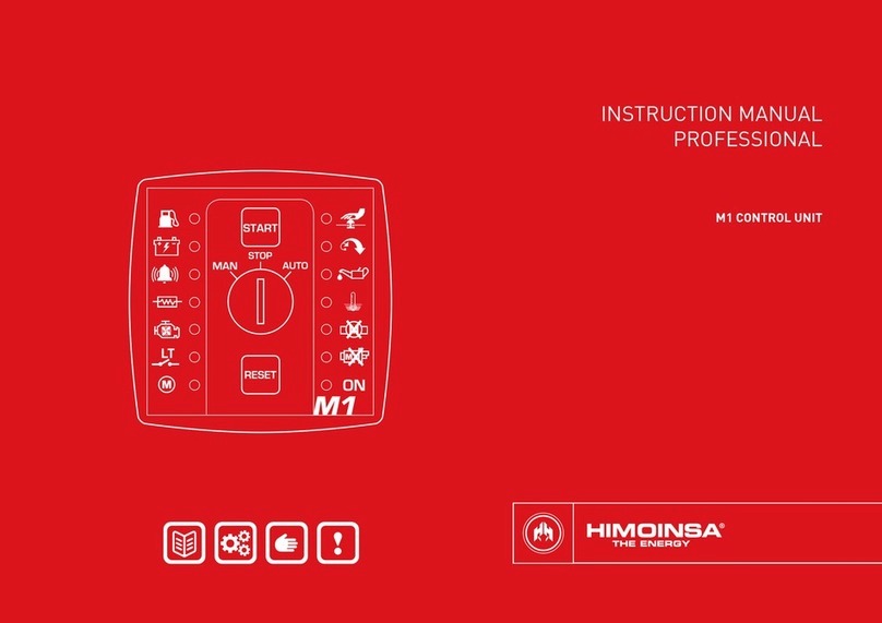
Himoinsa CEC7 User manual

INSTRUCTION MANUAL
PROFESSIONAL
CEC7 DIGITAL SWITCHING CONTROL UNIT

| PAGE 2
CONTENTS
31. Introduction
52. Front of the display module
83. Operating modes
10 4. Connecting to the generator set
12 5. Operation
16 6. CEC7 control unit inputs and outputs
19 7. CEC7 control unit alarms
29 8. Maintenance
30 9. Options
32 10. Appendix I: parameters table
37 11. Appendix II: CEC7 control unit screens
47 12. Appendix III: synchronization
53 13. Appendix IV: dimensions, wiring, mechanical parts and electrical
characteristics
63 14. Appendix V: CEC communications
66 15. Appendix VI: calibration of the control unit

INTRODUCTION | PAGE 3
1. INTRODUCTION
The CEC7 control unit is an electric network signal supervision device and
conducts supervision and control of power supply through the generator set. The
control unit consists of 2 different modules:
•Display module. The display module is responsible for carrying out the
information tasks regarding the status of the device and allows actions
to be performed by the user; through the display module the user is
able to control the control unit, as well as program and congure the
functions. Through the display module, access is given to a record of
the last 100 errors registered by the control unit.
•Measurements module. The measurements module is responsible for
performing the tasks of monitoring and control of the control unit. This
module is located in the rear panel to reduce wiring and increase the
control unit's immunity against electromagnetic noise. All the signal,
sensor and actuators are connected to the measurements module.
(see appendix III).

INTRODUCTION | PAGE 4
The following additional modules can be added as options via the CAN bus:
•CAN/USB.
•C2CLOUD (GPRS and eet manager).
•CAN/485 (MODBus).
•CAN2LAN.
•CAN2LAN (MODBUS IP).
•CAN2LAN HG FLEET MANAGER.
•CAN2LAN (SNMP).
1.1 MEASUREMENTS MODULE
The measurements module provides the following electrical signal characteristics,
both those generated and those from the network itself:
•Phase-neutral voltage.
•Phase-to-phase voltage.
•Current phase.
•Frequency.
•Active, apparent and reactive power.
•Power factor.
•Genset instant energy (kWh).
•THD (total harmonic distortion) of voltages and currents
•Calculation of harmonics up to order 20.
The measurement module provides the following electrical panel control
functions:
1. Electrical panel alarm inputs:
•Emergency stop (mushroom head stop button).
2. Congurable inputs; the measurements plate has 3 inputs that can be
programmed to perform the following functions:
•Network contactor conrmation.
•Conrmation of genset contactor.
•Enabling of genset breaker activation.
The measurements module has relay outputs to command activation of network
and genset contactors. It also has a relay to command the start-up of genset via
voltage free output.
The connection of the measurements module and display module is performed
via a CAN communications bus, enabling the interconnection between additional
modules which ensures the scalability of the control unit.

FRONT OF THE DISPLAY MODULE | PAGE 5
2. FRONT OF THE DISPLAY MODULE
The display module has a backlit display and various LEDs for monitoring the
status of the control unit. It also has keys that allow the user to control and
program the control unit.
Fig.1
CEC7 display module
1. Backlit display with 4 lines of 20 digits.
NOTE
The display goes into low power mode (backlight off) after 10 minutes without
any button being pressed.
2. Control unit buttons:
•Control unit operating mode buttons.
•Control unit command buttons.
•Activation button for genset contactor and network contactor.
3. Status LEDs:
•ELECTRIC SIGNAL status LEDs.
•CONTACTORS status LEDs.

FRONT OF THE DISPLAY MODULE | PAGE 6
2.1.3. DISPLAY BUTTONS
Confirm (V). Enter the menus and conrm the data
entered.
Cancel (X). Leave the menus and cancel the data entered.
Up (+). Advances through the selection of display screens,
the maintenance menus selection and increases the
programmed values.
Down (-). Go back through the selection on display screens,
the selection in maintenance menus and decrease the
programming settings.
2.1.4. CONTACTOR BUTTONS
Network contactor. Enables/disables the network contactor
(manual mode only).
Genset contactor. Enable/disable genset contactor (manual
mode only).
2.1 CONTROL UNIT BUTTONS
2.1.1. BUTTONS FOR CONTROL UNIT OPERATING MODES
Automatic mode. The control unit
monitors the status of the installa-
tion and manages its operation and
the programmable inputs.
Lit LED: Active mode.
LED flashing: Active
mode lock (automatic
and manual mode).
LED off: Mode not
active.
Test mode. The control unit starts
the engine while monitoring and
managing its operation.
Locked mode. The control unit
monitors the status of the installation,
but limits the startup of the engine.
Manual mode. The control unit is
commanded by the user.
2.1.2. CONTROL UNIT COMMAND BUTTONS
Engine start button (only in manual mode).
Manages start-up with one touch.
Lit LED: Engine started.
Engine stop button (only in manual mode).
The rst press stops the engine following a cooling cycle.
The second press stops the engine immediately.
Lit LED: Motor stopping (with or without cooling).
ALARMS RESET button.
Allows notication of the alarm by the user.
LED ashing: Alarms pending notication.
Lit LED: Alarms active.

FRONT OF THE DISPLAY MODULE | PAGE 7
2.2 STATUS LEDS
2.2.1. CONTACTORS STATUS LEDS
Network contactor status Lit: Contactor active.
Flashing: Contactor in the
connection/disconnection
phase.
Off: Contactor disconnected.
Genset contactor status
2.2.2. ELECTRIC SIGNAL STATUS LEDS
Network signal status Lit: Active status without
errors.
Flashing: Status with errors.
Off: Inactive status.
Engine status
Status of the generator set's
AC electric signal
2.3 PASSWORDS
The CEC7 control unit has 2 levels of 4-digit password to protect against unauthorized
access. The different levels of access are as follows:
•User (default password: 1111). User level access allows the operator to
access the main menu of the CEC7 control unit.
•Maintenance (default password: 1911). Maintenance level access
allows the operator to access the Parameters programming option
from the main menu.
The CEC7 control unit's passwords are customizable by the user from the main
menu. A user can congure both passwords for their access level and lower-level
passwords.
NOTE
To enter a password, see Appendix II: Password entry.

OPERATING MODES | PAGE 8
3. OPERATING MODES
3.1 MANUAL MODE
In manual mode, the control unit is commanded by the user via the front panel of
the display module. The user can start and stop the engine by pressing the
START and STOP keys respectively.
Pressing the START key initiates the engine starting procedure (without
deactivating the network contactor). Pressing the STOP key initiates the engine
stopping procedure with cooling; a second press of the STOP key causes the
engine to stop immediately without waiting for the cooling time.
x 1 click
WITH cooling
x 2 (double click)
WITHOUT cooling
NOTE
In manual mode, the control unit's protection devices remain active, being able
to produce alarms that cause the engine to stop.
In manual mode, the control unit does not take into consideration the start
conditions (programmed, by external signal) that can be programmed.

OPERATING MODES | PAGE 9
3.4 LOCKED MODE
In Lock mode , the control unit disables the genset startup under any
condition.
3.5 AUTOMATIC MODE LOCK
Pressing the AUTO or MAN keys for 5 seconds activates the mode lock. This
status of the control unit is indicated by the ashing of the button for the mode
currently active. To deactivate the mode lock and allow normal operation of the
control unit, press the key associated to the active mode for 5 seconds.
5’’ Locked 5’’ Unlocked
5’’ Locked 5’’ Unlocked
Furthermore, activation of the network and genset contactors is performed by
pressing the RED/MAINS and GROUP/GEN keys.
In order to achieve activation of the genset contactor, the engine has to be
running and provide a stabilised electrical signal. Activation of the genset
contactor deactivates the network contactor and vice versa; there is a time delay
between activation of contactors of 1 second (not programmable).
3.2 AUTOMATIC MODE
In automatic mode supervision of the installation is managed by the control unit.
Under certain conditions which can be programmed, the control unit starts the genset
activating the genset contactor to power the installation.
Programmable conditions for genset starting and activation of the genset
contactor include:
•Maximum network voltage alarm (Alarms table, parameter 88).
•Minimum network voltage alarm (Alarms table, parameter 90).
•Maximum network frequency alarm (Alarms table, parameter 92).
•Minimum network frequency alarm (Alarms table, parameter 94).
•Network sequence alarm (Alarms table, parameter 96).
•Network failure alarm (Alarms table, parameter 98).
•Network contactor failure alarm (Alarms table, parameter 100).
•Programmed start time (if a schedule timer is available).
3.3 TEST MODE
In test mode , the control unit starts the genset following the procedure
explained in the section Engine Starting except the activation of contactors
except in the event a network failure occurs.
In Test mode, the control unit does not manage the functions associated with the
programmable inputs except those relating to alarms, analogue inputs and the
starter disable function of the control unit (IA).

CONNECTING TO THE GENERATOR SET | PAGE 10
4. CONNECTING TO THE GENERATOR SET
4.1 INTEGRATED OPERATION MODE
With the operation mode integrated into the genset, communication between the
manual control unit of the generator set (only for manual CEM7 gensets) and the
transfer switch controller is established, sharing information between the transfer
switch controller and the generator set control unit.
The integrated control mode on the generator set is programmed in the CEC7
control unit (Regulations table, parameter 30, values 0 and 1).
4.2 EXTERNAL TO GENSET OPERATION MODE
With the external to genset operation mode, the switching control unit monitors
the status of the generator set (started, stabilized,...) through the measured
generator voltage, without the need to communicate with the genset control unit.
The transfer switch controller commands the start-up or stopping of the generator
set via the BT voltage free contact.
The external control mode on the generator set is programmed in the CEC7
control unit (Regulations table, parameter 30, values 2).
4.3 EXTERNAL TO GENSET SMART OPERATION MODE
With the external to genset smart operation mode, the control unit monitors the
status of the generator set (started, stabilized, etc.) through the measured gener-
ator voltage, without the need to communicate with genset control unit. The
transfer switch controller commands the start-up or stopping of the generator set
via the BT voltage free contact.

CONNECTING TO THE GENERATOR SET | PAGE 11
In this mode, the transfer switch controller is congured to consider there to be
genset stopped conditions not ordered by the transfer switch controller. The oper-
ating conditions that this mode considers are:
•Cancels the cooling time at the generator set stop. The genset is
considered to already carry out a cooling process before performing
the engine stop.
•The genset quality alarms (minimum and maximum voltage, minimum
and maximum frequency, phase voltage sequence and asymmetry)
do not cause the generator set to stop, but they open the genset
contactor. The group contactor is closed when the condition that
caused the genset signal quality alarm disappears without the need
for the operator to reset the alarm.
•The genset signal drop is not considered to be an alarm since there
may be external conditions that cause the generator set to stop. The
genset signal drop condition causes the genset contactor to open.
The external control mode on the generator set is programmed in the CEC7 con-
trol unit (Regulations table, parameter 30, value 3).

OPERATION | PAGE 12
5. OPERATION
5.1 START-UP OF THE GENSET
Under the conditions for activating the control unit, proceed to perform the
following engine start procedure:
1. Conditions for start-up of the generator set:
In automatic mode:
•Electrical signal to the network not valid (Alarms table, parameters 88 to 99).
•Network contactor activation failure (Alarms table, parameter 100).
•Start programmed by schedule.
•Start-up by load demand (see section 5.3).
In manual mode, by pressing the START key.
2. Start delay. Once activation conditions are detected, it is possible to program
a time delay (Times table, parameter 3) before continuing the engine start up
procedure. This delay only applies to engine starts in automatic mode.
3. Start-up of the generator set. The CEC7 control unit commands the start-up
of the generator set:
•Via the LT breaker in CEC7 control units congured in external mode.
•Via the communications bus in CEC7 control units congured in
integrated mode with CEM7 control units.
4. Engine started. Once the CEC7 control unit detects that the generator set is
running, the CEC7 control unit begins to validate the genset signal generated
according to the programming indicated for each enabled alarm (Alarms table,
parameters 104 to 110).

OPERATION | PAGE 13
5.3 START-UP BY LOAD DEMAND
DESCRIPTION:
This function enables automatic start up and activation of generator set charging
depending on the power consumption of the network.
Start up is performed based on the programming of a maximum network power
threshold (kW) that is consumed by the installation over a certain period of time.
Once the generator set is started, the system changes genset power leaving the
network free of load.
Once the power consumed by the installation is below the set threshold and the
set time has elapsed, the system returns to charging the installation from the
network and the genset begins its stopping cycle.
With the CEC7 control unit associated to a CEM7 genset control unit (Regulations
table, parameter 30, value 0), the current measurement transformers must be
installed on the CEC7 network line (Regulations table, parameter 24, value 2) to
enable start up by load demand.
With the CEC7 control unit congured for external control of the genset
(Regulations table, parameter 30, value 2), the current measurement
transformers must be installed on the CEC7 output line (Regulations table,
parameter 24, value 1) to enable start up by load demand.
PROGRAMMING:
The generator set will start operating, providing the power supply to the
installation, when network power consumption is detected which is more than
the limit set by parameter (Threshold table, parameter 34). The genset will
continue to operate until the genset power consumption measured falls below a
limit set by parameter (Thresholds table, parameter 35). Both with the start and
stop of the genset by load demand, the conditions must be validated for a
programmable time (Times table, parameter 27). The function of start up by load
demand is only enabled in Automatic mode of the CEC7 control unit.
5.2 ENGINE STOP
The engine stopping process affects the following operation:
1. Conditions for stopping the generator set:
In automatic mode:
•Network electrical signal validation.
•RESET of network contactor activation failure alarm.
•End of programmed Start-up time period.
•Stop by load demand (see section 5.3).
In manual mode, by pressing the STOP key.
2. Switching contactors. The CEC7 control unit performs the deactivation of the
genset contactor. In automatic mode, if the network signal is correct and there is
no network contactor activation failure alarm, the control unit performs the
activation of the network contactor.
3. Cooling the engine. Once voltage free, the CEC7 control unit commands a
cooling stop of the generator set, during which the engine will continue to run for
a congurable time (Times table, parameter 11). In certain situations, it is
possible to congure the control unit alarms to perform a stop without engine
cooling.
4. Engine stop. The CEC7 control unit commands the stopping of the generator
set:
•Via the LT breaker in CEC7 control units congured in external mode.
•Via the communications bus in CEC7 control units congured in
integrated mode with CEM7 control units
5. Engine stopped. The CEC7 control unit checks the engine stop via the
electrical signal of the generator set.

5.6 SECOND ZERO
DESCRIPTION:
The CEC7 control unit makes it possible to avoid the zero in the power supply
upon the return of the network via the Second Zero (SZ7) expansion. This
function is only enabled if the control unit of the genset is from the CEM7 family
and has the Second Zero (SZ7) module installed. With the second zero function
enabled, the activation process of genset contactors in automatic mode upon
the return of the network signal is performed after synchronizing the phase,
frequency and amplitude of the network and genset electrical signals. Upon
activation of the genset contactor, the control unit performs a controlled transfer
of the load taken from the network to the genset prior to opening the network
contactor.
PROGRAMMING:
Enabling the second zero function is performed by programming a control unit
parameter (Synchronization table, parameter 1 values 1 and 2) if the Second
Zero (SZ7) device is detected in the installation.
5.7 HEATER
DESCRIPTION
The screen of the control unit has a heater which allows it to work at low temper-
atures. The control unit maintains a minimum screen temperature by means of a
heater, thereby ensuring that on-screen information can be refreshed.
PROGRAMMING
Enabling the reserve screen heater function is performed by programming a con-
trol unit parameter (Screen table, parameter 3, value 1). The minimum screen
temperature ensured by the screen heater is programmed through a control unit
parameter (Screen table, parameter 11).
5.4 ENABLING THE GENSET CONTACTOR
DESCRIPTION:
This function makes it possible to assign to a programmable input of the CEC7
control unit the ability to stop the activation of the genset contactor. In this way,
once the control unit detects the start condition of the generator set and
validates that the genset electrical signal is stable, the CEC7 control unit waits
to activate the genset contactor until it detects an active signal at the
programmable input assigned to this function.
PROGRAMMING:
The function enabling the genset contactor is performed by assigning a
programmable input to that function (Settings table, parameter 8).
5.5 GENSET IN RESERVE
DESCRIPTION:
The genset in reserve function allows the operation of several generator sets in
the same installation. With this function, the CEC7 control unit selects the start-
up of the generator set with the fewest hours of engine operation.
PROGRAMMING:
Enabling the genset in reserve function is performed by programming a control
unit parameter (Settings table, parameter 31, values 4 to 7). The control units of
the CEM7 genset must also have the genset in reserve function enabled (Settings
table, parameter 31, values 4 to 7).
OPERATION | PAGE 14

OPERATION | PAGE 15
5.8 TIMER.
The CEC7 control unit has a timer that tells the control device the current time
and date. This device allows the weekly programming of:
•Scheduled start-ups.
•Scheduled locks.
•Scheduled engine tests and maintenance.
•Energy counters (day, month, year).
The maximum timer limit is 5 daily programs. The CEC7 control unit must be in
automatic mode in order to manage the incorporated programming.

CEC7 CONTROL UNIT INPUTS AND OUTPUTS | PAGE 16
6. CEC7 CONTROL UNIT INPUTS AND OUTPUTS
The CEC7 control unit's digital inputs - ENT1, ENT2 and ENT3- have a debounce
time associated (Times table, parameters 22 to 24) which requires that the value
of the input is stable over a time interval. Also, the CEC7 control unit's inputs can
be congured to be active with contact closed to earth or be inactive with contact
closed to earth (Regulations table parameters 11 to 14).
The status of the CEC7 control unit's inputs and outputs can be monitored from
the Main menuà1.Inputs/Outputs. From that position, a screen displays the
status of the control unit's digital inputs and outputs:
* I N P U T S / O U T P U T S *
3 2 1 0 9 8 7 6 5 4 3 2 1
I N : 3 2 1 P
O U T : B g r
IN: Input
OUT: Outputs
Index of the input/output. Ordered from 13 to 1
Detection of an active input is indicated by the following characters:
•IN 1. P: Emergency stop (PEM).
•IN 2. 1: Programmable input 1.
•IN 3. 2: Programmable input 2.
•IN 4. 3: Programmable input 3.
Detection of an active output is indicated by the following characters:
•OUT 1. r: Network contactor (CRC, CRNA, CRNC).
•OUT 2. g: Genset contactor (CGC, CGNA, CGNC).
•OUT 3. B: Free voltage contact genset start (BTNA, BTA).
By pressing the up or down scroll keys it is possible to display the analogue
inputs of the generator set.

CEC7 CONTROL UNIT INPUTS AND OUTPUTS | PAGE 17
6.2 PROGRAMMABLE INPUTS
The CEC7 control unit's measurements module has 3 digital inputs with operation
that can be programmed. The programmable inputs can be congured to have
the following behaviour:
Confirmation of network contactor (CKR)
The input congured as network contactor conrmation (Settings table, parameter
5) is used to verify the correct activation of the network contactor. Upon activation
of the network contactor, a time interval begins (Times table, parameter 13) for
verication of the contactor through the activation of the network contactor
conrmation input. If after this time has elapsed there is no conrmation of the
activation of the network contactor and the control unit does not detect a network
failure alarm, a network contactor alarm is generated (Alarms table, parameter
100). If the control unit is operating in automatic mode, the genset is started
with activation of the genset contactor for the supply of the installation.
Confirmation of genset contactor (CKG)
The input congured as genset contactor conrmation (Settings table, parameter
6) is used to verify the correct activation of the contactor. Upon activation of the
genset contactor, a time interval begins (Times table, parameter 13) for
verication of the contactor through the activation of the genset contactor
conrmation input. If after this time has elapsed there is no conrmation of the
activation of the genset contactor, a genset contactor alarm is generated (Alarms
table, parameter 102). If the control unit is operating in automatic mode, a stop
occurs with engine cooling and activation of the genset contactor if it is within
the valid operating parameters.
Enabling of genset contactor activation (HKG)
This function is only managed in automatic mode of the CEC7 control unit. The
input congured as enabling genset contactor activation (Settings table,
parameter 8) inhibits the activation of the genset contactor until the input is
active after stabilization of the genset electrical signal.
A N A L O G U E I N P U T S
N C 0 . 0 ΩP A 0 . 0 Ω
T M 0 . 0 Ω A A 0 . 0 Ω
D I 0 . 0 V V B 0 . 0 V
The value of the resistance analogue inputs is shown in ohms and the voltage
analogue inputs in volts. The various inputs displayed are:
•NC: Fuel level.
•PA: Oil pressure.
•TM: Engine temperature.
•AA: Auxiliary analogue.
•DI: Alternator voltage.
•VB: Battery voltage.
6.1 DIGITAL INPUTS
Emergency stop (PEM)
Digital signal notifying the control unit that an immediate stop of the engine must
be performed without cooling.

CEC7 CONTROL UNIT INPUTS AND OUTPUTS | PAGE 18
NOTE
Activation of the genset contactor is performed with a programmable time after
detecting that the engine is in operation (Table times, parameter 6), it being
possible to dephase the activation of both outputs —the genset contactor and
programmed output in STABILIZED ENGINE mode— by programming the
parameter.
Neutral to earth switch output.
The earth switch output of the CEC7 control unit is assigned to the SC relay
output which is responsible for isolating the generator set neutral from the
earthing of the installation during the time of simultaneous activation of genset
and network contactors during synchronization. The allocation of the stabilized
genset electrical signal function to the SC output is carried out by programming
the control unit (Synchronization table, parameter 1 value 2).
6.3 PROGRAMMED DIGITAL OUTPUTS
The CEC7 control unit has 3 specic-purpose outputs . The functioning of these
outputs is preset by default values but can be modied by setting the control
unit.
Network contactor output (CR) - Relay output
The network contactor output (CR) of the CEC7 control unit is a relay output that
manages the closing and opening of the network contactor.
Genset contactor output (CG) - Relay output
The genset contactor output (CG) of the CEC7 control unit is a relay output that
manages the closing and opening of the genset contactor.
Genset start-up (LT) - Relay output
The engine start-up output (LT) of the CEC7 control unit commands the generator
set start-up via a voltage free output. This start-up mode is useful for integrating
the CEC7 transfer switch controller with generator sets controlled by control units
without communication.
6.4 PROGRAMMABLE OUTPUTS
The CEC7 control unit has 1 programmable relay output (SC) with operation which
can be congured to indicate certain states (Synchronization table, parameter 1).
The possible congurations that are permitted with the programmable outputs
are:
Output of stabilized genset electrical signal
The stabilized genset electrical signal output from the CEC7 control unit is
activated once the stabilization time of the genset electrical signal has elapsed
after the genset start-up is detected (Times table, parameter 7) and remains
active until the generator set engine stops after the cooling time (Times table,
parameter 11). The allocation of the stabilized genset electrical signal function to
the SC output is carried out by programming the control unit (Synchronization
table, parameter 1 value 0 and 1).

CEC7 CONTROL UNIT ALARMS | PAGE 19
7. CEC7 CONTROL UNIT ALARMS
The CEC7 control unit has a list of alarms, the operation of which can be congured
so that actions are performed or so that they are shown on the display module
screen.
The CEC7 control unit, working with a generator set control unit from the CEM7
family, integrates the generator set alarms in its operation, allowing the
management of genset and switching alarms from any screen connected to the
system.
The CEC7 control unit distinguishes between errors that cause the stopping of the
engine (alarms with generator set stop), deactivation of the genset contactor
(installation power interruption alarms) and errors that do not cause stopping of
the engine (warnings).
Upon detection of an alarm or warning, the control unit produces an acoustic
signal, which activates the alarm digital output (AL) and the LED of the RESET
button and the display screen ashes. This condition will remain as long as the
error condition continues for a programmable maximum period of time (Times
table, parameter 14).
When there is an alarm, active warning or pending notication, the LED of the
RESET button remains illuminated. Pressing the RESET button allows the user to
view a list of alarms, active warnings and pending notication. To scroll through the
list of errors use the buttons on the display . A second press of the RESET
button allows notication of the alarm which disappears from the list of active
alarms if the condition that caused it is no longer present.
The alarms related to the network signal cause the ashing of the LED associated
with the network signal condition .
The alarms related to the genset signal cause the ashing of the LED associated
with the genset signal condition .

CEC7 CONTROL UNIT ALARMS | PAGE 20
EXAMPLES OF ALARM OPERATIONS
•“EN” Alarm with engine stopped
•“AN” Warning that needs to be reset
•“A” Auto-resettable warning
“EN” ALARM WITH ENGINE STOPPED
1. Upon detection of an alarm or warning, the control unit produces an acoustic
signal, the LED of the RESET button and the screen ashes and the alarm digital
output (AL) is activated.In this case the engine stops. (1)
Fig.1
2. Pressing the RESET button eliminates the acoustic warning and the screen
stops ashing. The RESET LED remains lit and on the screen the alarm type is
displayed. Example: Alarm active “EN” High Water Temperature. (2)
Fig.2
The list of alarms, active warnings and pending notication has the following
format:
* A L A R M * E N 1 /3*
M I N . G E N S E T F R E Q U E N C Y
E: Alarm / A: Warning
N: Pending notication
1: Position of the error in the list of errors
3: Total number of errors in the list
NOTE
Alarms that cause the engine to stop are not auto-resettable, they must be
notied and reset so that the generator set can be restarted, provided that the
alarm does not remain active.
Alarms associated with the network electrical signal are auto-resettable,
disappearing from the display screen once a valid electrical signal is restored.
ALARM
HIGH WATER TEMPERATURE
Table of contents
Other Himoinsa Control Unit manuals
