manuals.online logo
Brands
  1. Home
  2. •
  3. Brands
  4. •
  5. Johnson Controls
  6. •
  7. Control Unit
  8. •
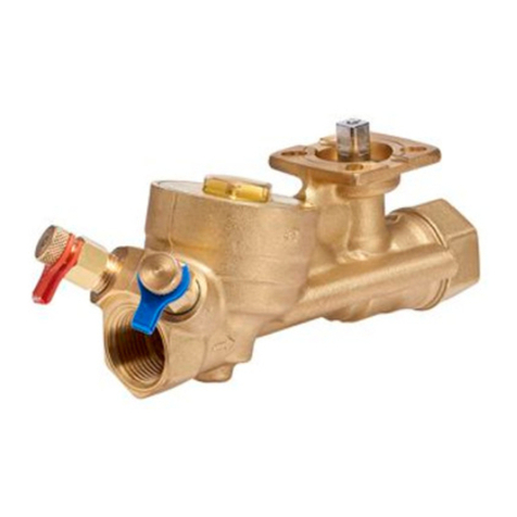
  9. Johnson Controls VP101DBB User manual

Johnson Controls VP101DBB User manual

INSTRUCTIONS
PRESSURE INDEPENDENT AUTOMATIC
BALANCING AND ROTARY CONTROL VALVE
Technical
data
VP101DBB
VP101EBB
VP101EBC
VP101EBD
VP101FBD
VP101FBF
VP101GBF
Max flow rate
6000 l/h
1.667 l/s
6000 l/h
1.667 l/s
9000 l/h
2.5 l/s
11000 l/h
3.056 l/s
12000 l/h
3.33 l/s
18000 l/h
5.0 l/s
18000 l/h
5.0 l/s
Flow accuracy
[∆p 0.2 ÷ 1 bar]
±5%
±5%
±5%
±5%
±5%
±5%
±5%
Start-up
∆p →Q=const.
30 kPa
0.30 bar
30 kPa
0.30 bar
35 kPa
0.35 bar
40 kPa
0.40 bar
35 kPa
0.35 bar
35 kPa
0.35 bar
35 kPa
0.35 bar
Max ∆p
600 kPa
6 bar
600 kPa
6 bar
600 kPa
6 bar
600 kPa
6 bar
400 kPa
4 bar
400 kPa
4 bar
400 kPa
4 bar
Temperature
-10 ÷ 120°C
-10 ÷ 120°C
-10 ÷ 120°C
-10 ÷ 120°C
-10 ÷ 120°C
-10 ÷ 120°C
-10 ÷ 120°C
Max working
pressure
1600 kPa
16 bar
1600 kPa
16 bar
1600 kPa
16 bar
1600 kPa
16 bar
1600 kPa
16 bar
1600 kPa
16 bar
1600 kPa
16 bar
Connections
Rc 1.1/4” F
EN10226-1
Rc 1.1/2” F
EN10226-1
Rc 1.1/2” F
EN10226-1
Rc 2” F
EN10226-1
Rc 2” F
EN10226-1
Rc 2” F
EN10226-1
G 2.1/2” M
EN ISO 228
VALVE FEATURES
03-05-2016 Subject to change without prior notice
1. EQUAL PERCENTAGE
CONTROL VALVE
Control valve fully open, controls
the flow through a profiled ball and
provides modulation via a 90°
rotating actuator.
2. FLUSHING MODE
Control valve rotated by 180°, profiled
opening outside flow path. The valve
now has full port passage, allowing twice
maximum flow, for proper flushing.
3. MANUAL SHUT OFF
VALVE
Arrow on
valve body
0176 (B)
Arrow on
stem valve
Arrow on
valve body
Arrow on
stem valve
6mm
It is possible to manually shut off the valve,
by screwing the headwork from the bottom
side with an allen key
180°
Flow
European Single Point of Contact:
JOHNSON CONTROLS
WESTENDHOF 3
45143 ESSEN
GERMANY.
NA/SA Single Point of Contact:
JOHNSON CONTROLS
507 E MICHIGAN ST
MILWAUKEE WI 53202
USA.
APAC Single Point of Contact:
C/O CONTROLS PRODUCT MANAGEMENT
NO. 22 BLOCK D NEW DISTRICT
WUXI JIANGSU PROVINCE 214142
CHINA.
During cleaning operation of the valve use a damp cloth, DO NOT use any detergent or chemical solvent that could
seriously damage the parts.
Pre-setting assembly
Assembled
PRESSURE READING FOR VERIFICATIONS
ASSEMBLING MANUAL FLOW PRE-SETTING DEVICE
P1 = Hpressure port
P2 = Lpressure port
Q≠CONST
Q=CONST
30 kPa
P1-P2
Q
START UP
PRESSURE
IF P1-P2 > START UP PRESSURE THEN
THE VALVE IS WITHIN THE WORKING RANGE
Orientate these
components with the
arrow or notch in the
same direction as the
arrow marked on the
valve body.
3mm allen key
NB: In the pre-setting plastic bag you will find also
n°4 cross head screws M5 x 30mm that you will
need to attach the actuator linkage on the valve
when the pre-setting device is on.
PRE-SETTING COMPONENTS
1. n°2 countersunk head screw M5x20
2. Pre/setting body
3. Memory stop
4. P.T.F.E. anti-friction ring
5. Control stem
6. n°2 Hexagon socket set screw M6x12
2
3
4
5
6
1
Johnson Controls does not accept any liability for improper or wrong use of this product.
Always protect the pressure regulator by using strainers upstream of the valve and, in any case, make sure water
quality complies with UNI 8065 standards (Fe < 0.5 mg/kg and Cu < 0.1 mg/Kg).
Furthermore, maximum iron oxide in the water passing through this product should not exceed 25 mg/Kg (25 ppm). To
ensure the main pipework is cleaned appropriately, flushing by-passes should be used without flushing through the pressure
regulator of the PICV thereby preventing debris that might clog the valve.
COMPLIANCE: Johnson Controls, Inc., declares that this product is in compliance with the essential requirements
and other relevant provisions of the PED (Pressure Equipment Directive).
MOTOR CONNECTION ISO 5211 :
Valve neck detail
MANUAL FLOW PRE-SETTING DEVICE INSTRUCTION
VP101DBB
VP101EBB
VP101EBC
VP101EBD
VP101FBD
VP101FBF
VP101GBF
PRE-
SETTING %
Flow
l/h
Flow
l/s
Flow
l/h
Flow
l/s
Flow
l/h
Flow
l/s
Flow
l/h
Flow
l/s
Flow
l/h
Flow
l/s
Flow
l/h
Flow
l/s
100%
6000
1.667
9000
2.50
11000
3.056
12000
3.333
18000
5.00
18000
5.00
90%
5400
1,500
8100
2.25
9900
2,750
10800
3.000
16200
4.50
16200
4.50
80%
4800
1,333
7200
2.00
8800
2,444
9600
2.667
14400
4.00
14400
4.00
70%
4200
1,167
6300
1.75
7700
2,139
8400
2.333
12600
3.50
12600
3.50
60%
3600
1,000
5400
1.50
6600
1,833
7200
2.000
10800
3.00
10800
3.00
50%
3000
0,833
4500
1.25
5500
1,528
6000
1.667
9000
2.50
9000
2.50
40%
2400
0,667
3600
1.00
4400
1,222
4800
1.333
7200
2.00
7200
2.00
30%
1800
0,500
2700
0.75
3300
0,917
3600
1.000
5400
1.50
5400
1.50
20%
-
-
-
-
-
-
-
-
-
-
-
-
10%
-
-
-
-
-
-
-
-
-
-
-
-
CONTROL VALVE ACTUATORS
1. Close the valve
by using a 9mm
wrench. In case
the actuator is on,
fully close the valve
by using a control
signal applied to the
actuator or use the
manual override.
2. Release the two hexagon
socket set screws (Aand B)
of the locking device using
3mm allen key.
3. Set maximum
flow rate by
rotating the
highlighted red ring
indicator.
4. Lock again the two
hexagon socket set
screws (Aand B) and
re-open the valve.
Torque 3÷4 Nm
B
A
B
A
Mounting position: any between vertical and horizontal. Mounting upside down should be avoided
CONTROL VALVE ACTUATORS
Actuator assembly with
pre-setting device on.
For the calibration of the VA9310
proceed as follow:
The Calibration function enables the actuator to redefine the
selected input signal range proportionally across a reduced
rotation range. The actuator maintains calibration when power is
lost or removed.
Locate the oval cover on the front of the unit and pull the cover
outward. See figure below for iewing the DIP switches and
LEDs meaning.
With power applied to the actuator, press Enter/Autocal until all
three LEDs are on.
The CAL function enables the actuator to redefine the selected
input signal range proportionally across a reduced rotation
range. The actuator maintains calibration when power is lost or
removed.
Follow these steps to calibrate the input signal range:
1. With power applied to the actuator, move the mode selection
switch to the CAL position and leave it in this position for
approximately 5 seconds. The actuator begins rotating until
the end-stops are found.
2. Move the mode selection switch to the desired input signal
range. Selection can be made while the calibration process is
in progress, or after it is complete. The selected input signal is
proportionally reconfigured to the reduced rotation range.
Note: During normal operation, if the actuator stroke
increases due to seal or seat wear, input signals are automatically
reconfigured to the increased rotation range in approximately 0.5°
increments.
3. If the actuator mounting position is changed or if the linkage is
adjusted, repeat Step 1 and Step 2 to repeat the CAL function.
Note: The mode selection switch must remain out of the CAL
position for at least 2 seconds before re-initiating the
CAL function.
Note: If the mode selection switch is left in the CAL position,
the actuator defaults to 0-10 V input signal range, DA.
Calibration (CAL) Function actuators
valid for VA9208-GGx-1 Series
The actuator begins rotating until the end-stops are found.
When the actuator reach the starting position and stops it’s
calibrated and ready to work.
Remove the oval
cover
Remove the oval
cover
DIP Switches LEDs Placement

This manual suits for next models

6

Other Johnson Controls Control Unit manuals
Johnson Controls S1-TTSCC01 User manual

Johnson Controls

Johnson Controls S1-TTSCC01 User manual

Johnson Controls Tyco DV-5a Series User manual
Johnson Controls

Johnson Controls Tyco DV-5a Series User manual

Johnson Controls MS-NCM4510-2 User manual

Johnson Controls

Johnson Controls MS-NCM4510-2 User manual

Johnson Controls PENN P70 Series Manual

Johnson Controls

Johnson Controls PENN P70 Series Manual

Johnson Controls MS-IOU4710-0U User manual

Johnson Controls

Johnson Controls MS-IOU4710-0U User manual

Johnson Controls IOM3731 User manual

Johnson Controls

Johnson Controls IOM3731 User manual

Johnson Controls NIE39 User manual

Johnson Controls

Johnson Controls NIE39 User manual

Johnson Controls LP-FXGPRSU-0 User manual

Johnson Controls

Johnson Controls LP-FXGPRSU-0 User manual

Johnson Controls CKM-F8P Manual

Johnson Controls

Johnson Controls CKM-F8P Manual

Johnson Controls MP8000 Series User manual
Johnson Controls

Johnson Controls MP8000 Series User manual

Johnson Controls Tyco HSM3408 User manual

Johnson Controls

Johnson Controls Tyco HSM3408 User manual

Johnson Controls System 450 Series User manual

Johnson Controls

Johnson Controls System 450 Series User manual

Johnson Controls TrueRH Series Guide

Johnson Controls

Johnson Controls TrueRH Series Guide

Johnson Controls IOM3711 User manual

Johnson Controls

Johnson Controls IOM3711 User manual

Johnson Controls Y20EBD Series Service manual

Johnson Controls

Johnson Controls Y20EBD Series Service manual

Johnson Controls METASYS TC-9102 Series Service manual

Johnson Controls

Johnson Controls METASYS TC-9102 Series Service manual

Johnson Controls A19ZBC Series Service manual

Johnson Controls

Johnson Controls A19ZBC Series Service manual

Johnson Controls M4-XPM User manual

Johnson Controls

Johnson Controls M4-XPM User manual

Johnson Controls Tyco DV-5a Series User manual

Johnson Controls

Johnson Controls Tyco DV-5a Series User manual
Johnson Controls GS-20 Series User manual

Johnson Controls

Johnson Controls GS-20 Series User manual

Johnson Controls VP1000 Series User manual

Johnson Controls

Johnson Controls VP1000 Series User manual

Johnson Controls IOM3723 User manual

Johnson Controls

Johnson Controls IOM3723 User manual

Johnson Controls C450CCN-2 User manual

Johnson Controls

Johnson Controls C450CCN-2 User manual

Johnson Controls A19 Series User manual

Johnson Controls

Johnson Controls A19 Series User manual

Popular Control Unit manuals by other brands

M-system R7ML-DC16B instruction manual

M-system

M-system R7ML-DC16B instruction manual

Sinopulsar SPTS01 user manual

Sinopulsar

Sinopulsar SPTS01 user manual

G.R.A.S. 12AR instruction manual

G.R.A.S.

G.R.A.S. 12AR instruction manual

Kimray DACC2000 user manual

Kimray

Kimray DACC2000 user manual

Watermark SS-TH1000 Installtion Guide

Watermark

Watermark SS-TH1000 Installtion Guide

Wieland gesis RM Series installation instructions

Wieland

Wieland gesis RM Series installation instructions

VIPA SLIO FM 050-1BB30 manual

VIPA

VIPA SLIO FM 050-1BB30 manual

Overkiz Hattara DIN Rail CU quick start guide

Overkiz

Overkiz Hattara DIN Rail CU quick start guide

UNICORECOMM UM220-IV M0 Installation and Operation User Manual

UNICORECOMM

UNICORECOMM UM220-IV M0 Installation and Operation User Manual

Kohler TOUCHLESS K-13686 installation instructions

Kohler

Kohler TOUCHLESS K-13686 installation instructions

Whelen Engineering Company CenCom Core C399 installation guide

Whelen Engineering Company

Whelen Engineering Company CenCom Core C399 installation guide

Pentair FLECK 5812 XTR2 Service manual

Pentair

Pentair FLECK 5812 XTR2 Service manual

National Instruments Phase Matrix PXI-1420 quick start guide

National Instruments

National Instruments Phase Matrix PXI-1420 quick start guide

Honeywell DIAL-SET DS05C Product data

Honeywell

Honeywell DIAL-SET DS05C Product data

M-system R7HL-DC16B-R instruction manual

M-system

M-system R7HL-DC16B-R instruction manual

Fuji Electric P642 Series Mounting instruction

Fuji Electric

Fuji Electric P642 Series Mounting instruction

ERR Cruise Commander Lite instruction manual

ERR

ERR Cruise Commander Lite instruction manual

Celestron SkyPortal 93973 manual

Celestron

Celestron SkyPortal 93973 manual

manuals.online logo
manuals.online logoBrands
  • About & Mission
  • Contact us
  • Privacy Policy
  • Terms and Conditions

Copyright 2025 Manuals.Online. All Rights Reserved.