Hino Series 155 Instruction manual
FOREWORD
This workshop manual has been prepared to provide information regarding repair procedures on Hino Trucks.
Applicable for HINO 155, 155h, 195, 195h series, equipped with J05E engine
When making any repairs on your vehicle, be careful not to be injured through improper procedures.
As for maintenance items, refer to the Owner's Manual.
All information and specifications in this manual are based upon the latest product information available at the time of printing.
Hino Motors Sales U.S.A., Inc. reserves the right to make changes at any time without prior notice.
Please note that the publications below have also been prepared as relevant workshop manuals for the components and sys-
tems in these vehicles.
Manual Name Pub. No.
Chassis Workshop Manual S1-LXJE03A
S1-LXJE03A EWD
J05E Engine Workshop Manual S5-LJ05E04A
Trouble shooting Workshop Manual
S7-LXJE03C 1/7
S7-LXJE03C 2/7
S7-LXJE03C 3/7
S7-LXJE03C 5/7
S7-LXJE03C 6/7
S7-LXJE03C 7/7
MENU

CHAPTER REFERENCES REGARDING THIS WORKSHOP MANUAL
Use this chart to the appropriate chapter numbers for servicing your particular vehicle.
CHAPTER
MANUAL No. S7-LXJE03C 4/7 (U.S.A.), S7-LXJE04C 4/7 (CANADA)
MODELS HINO 155, 155h, 195, 195h
Production Code XFC710, XFC720, XFC740, XJC700, XJC710, XJC720, XJC740
HYBRID 3-001

ENGINE
HYBRID
TRANSMISSION
CLUTCH
PROPELLER SHAFT
AXLE
DIFFERENTIAL
BRAKE
STEERING
FRAME AND FRAME ACCESSORY
CAB MOUNTING AND CAB SUSPENSION
BODY CONSTRUCTION
INDEX: TROUBLE SHOOTING GROUP 1/2
SUSPENSION
WORKSHOP
MANUAL
All rights reserved. This manual may not be
reproduced or copied in whole in part, with-
out the written consent of Hino Motors, Ltd.
BODY INSIDE ACCESSORY
BODY OUTSIDE ACCESSORY
AIR BAG AND SEAT BELT
HEATER AND AIR CONDITIONER
GENERAL INTRODUCTION

CONTROL SYSTEM
INDEX: TROUBLE SHOOTING GROUP 2/2
ELECTRICAL

HYBRID 3–1
3
HYBRID
3-001
TROUBLE SHOOTING .................................... 3-4
HYBRID CONTROL SYSTEM......................................3-4
TROUBLE SHOOTING STEPS
FOR HYBRID SYSTEM ..........................................3-4
SAFETY MEASURES
FOR HIGH-VOLTAGE WORK ...............................3-12
LIST OF CONNECTOR SYMBOLS ......................3-15
HV SYSTEM WIRING DIAGRAM .........................3-19
HEARING SHEET.................................................3-21
HYBRID ECU .............................................................3-22
DIAGNOSIS CODE TABLE...................................3-22
FREEZE FRAME DATA LIST ................................3-30
LIST OF DATA MONITOR ITEMS .........................3-33
COMMON INSPECTION CHART .........................3-36
DTC: P0500 (TC51) ..............................................3-41
DTC: P0501 (TC5B)..............................................3-51
DTC: P0562 (TC71) ..............................................3-57
DTC: P060B (TCB2) .............................................3-66
DTC: P0617 (TC59) ..............................................3-69
DTC: P062F (TCB3)..............................................3-78
DTC: P0810 (TC9C)..............................................3-81
DTC: P0810 (TC9D)..............................................3-85
DTC: P0A01 (TC7B) .............................................3-89
DTC: P0A02 (TC78)..............................................3-98
DTC: P0A03 (TC79)............................................3-106
DTC: P0A06 (TC7F)............................................3-113
DTC: P0A07 (TC7E) ...........................................3-125
DTC: P0A0F (TC31)............................................3-129
DTC: P0A1D (TC12) ...........................................3-133
DTC: P0A1D (TC17) ...........................................3-136
DTC: P0A78 (TC21)............................................3-139
DTC: P0A78 (TC22)............................................3-142
DTC: P0A7E (TC48) ...........................................3-145
DTC: P0A82 (TC67)............................................3-151
DTC: P0A84 (TC66)............................................3-164
DTC: P0A85 (TC65)............................................3-177
DTC: P0A90 (TC2A) ...........................................3-183
DTC: P0A92 (TC29)............................................3-195
DTC: P0A93 (TC7A) ...........................................3-210
DTC: P0AFD (TC6B)...........................................3-217
DTC: P0BCA (TC68)...........................................3-221
DTC: P0C73 (TC80)............................................3-227
DTC: P3000 (TC42) ............................................3-234
DTC: P3001 (TC41) ............................................3-243
DTC: P3001 (TC43) ............................................3-246
DTC: P3001 (TC44) ............................................3-249
DTC: P3001 (TC45) ............................................3-252
DTC: P3001 (TC46) ............................................3-255
DTC: P3001 (TC47) ............................................3-259
DTC: P3001 (TC4A)............................................3-263
DTC: P3001 (TC4B)............................................3-267
DTC: P3001 (TC4C)............................................3-270
DTC: P3009 (TC49) ............................................3-273
DTC: P3128 (TC7D)............................................3-289
DTC: P3129 (TC7C)............................................3-301
DTC: P314C (TC82)............................................3-306
DTC: P314D (TC81)............................................3-311
DTC: P324B (TC62)............................................3-323
DTC: P324C (TC61)............................................3-328
DTC: P33B1 (TC64)............................................3-334
DTC: P33B2 (TC63)............................................3-339
DTC: U0073 (TC11) ............................................3-345
DTC: U0074 (TC16) ............................................3-350
DTC: U0100 (TC13) ............................................3-354
DTC: U0101 (TC18) ............................................3-358
DTC: U0110 (TC14) ............................................3-365
DTC: U0111 (TC15) ............................................3-373
DTC: U0121 (TC24) ............................................3-381
DTC: U0155 (TC25) ............................................3-388
DTC: U110A (TC26)............................................3-395
DTC: U1136 (TC27) ............................................3-402
INVERTER................................................................3-409
DIAGNOSIS CODE TABLE .................................3-409
FREEZE FRAME DATA LIST ..............................3-415
DATA MONITOR ITEM LIST................................3-417
CONNECTION DIAGRAM ..................................3-420
INSULATION RESISTANCE MEASUREMENT
PROCEDURE FOR HYBRID MOTOR
[ROTATION MACHINE] .......................................3-421
DTC: P0562 (TC96) ............................................3-423
DTC: P0562 (TCA0)............................................3-433
DTC: P0604 (TC18) ............................................3-443
DTC: P0604 (TCD2)............................................3-445
DTC: P0605 (TC17) ............................................3-447
DTC: P0605 (TCD1)............................................3-449
DTC: P060B (TC1A) ...........................................3-451
DTC: P060C (TC1C) ...........................................3-454
DTC: P062F (TC41) ............................................3-456
DTC: P0A0D (TC20) ...........................................3-458
DTC: P0A1B (TC16) ...........................................3-465

HYBRID3–2
DTC: P0A1B (TC92)............................................3-472
DTC: P0A1B (TC97)............................................3-474
DTC: P0A1B (TC3F) ...........................................3-476
DTC: P0A1B (TCA1) ...........................................3-478
DTC: P0A1B (TCA2) ...........................................3-480
DTC: P0A1B (TCA3) ...........................................3-482
DTC: P0A1B (TCA4) ...........................................3-484
DTC: P0A1B (TCA5) ...........................................3-486
DTC: P0A1B (TCA6) ...........................................3-488
DTC: P0A1B (TCA7) ...........................................3-490
DTC: P0A1B (TCA8) ...........................................3-492
DTC: P0A1B (TCA9) ...........................................3-494
DTC: P0A1B (TCAA)...........................................3-496
DTC: P0A1B (TCBB)...........................................3-503
DTC: P0A1B (TCBC)...........................................3-505
DTC: P0A1B (TCBD)...........................................3-507
DTC: P0A1B (TCBE)...........................................3-509
DTC: P0A1B (TCBF) ...........................................3-511
DTC: P0A1B (TCD3) ...........................................3-513
DTC: P0A1B (TCD4) ...........................................3-515
DTC: P0A1B (TCD5) ...........................................3-517
DTC: P0A1D (TC21) ...........................................3-519
DTC: P0A2B (TCE9) ...........................................3-523
DTC: P0A2B (TCED)...........................................3-534
DTC: P0A2C (TCDA)...........................................3-545
DTC: P0A2D (TCDB) ..........................................3-555
DTC: P0A2F (TC33)............................................3-566
DTC: P0A3C (TC34) ...........................................3-573
DTC: P0A3F (TCB7) ...........................................3-593
DTC: P0A41 (TCC0) ...........................................3-602
DTC: P0A42 (TCC1) ...........................................3-614
DTC: P0A51 (TCD6) ...........................................3-626
DTC: P0A51 (TCD7) ...........................................3-629
DTC: P0A78 (TC13) ............................................3-632
DTC: P0A78 (TC14) ............................................3-645
DTC: P0A78 (TC15) ............................................3-664
DTC: P0AA1 (TCD8) ...........................................3-671
DTC: P0AA4 (TCD9) ...........................................3-678
DTC: P0ADB (TC1F)...........................................3-687
DTC: P0ADC (TC93)...........................................3-694
DTC: P0ADF (TC1E)...........................................3-702
DTC: P0AE0 (TC95)............................................3-709
DTC: P0AE6 (TC1D) ...........................................3-717
DTC: P0AE7 (TC94)............................................3-724
DTC: P0AEE (TC22) ...........................................3-732
DTC: P0AEE (TC23) ...........................................3-735
DTC: P0AEF (TC24) ...........................................3-738
DTC: P0AF0 (TC25)............................................3-742
DTC: P0BEA (TCB3)...........................................3-746
DTC: P0BEA (TCB4)...........................................3-749
DTC: P0BEB (TC9A)...........................................3-752
DTC: P0BEC (TC9B)...........................................3-755
DTC: P0BEE (TCB5)...........................................3-758
DTC: P0BEE (TCB6)...........................................3-761
DTC: P0BEF (TC9C)...........................................3-764
DTC: P0BF0 (TC9D) ...........................................3-767
DTC: P3126 (TC12) ............................................3-770
DTC: U0073 (TC91) ............................................3-783
DTC: U0074 (TC3E)............................................3-788
DTC: U0293 (TC31) ............................................3-792
BATTERY ECU .........................................................3-801
DIAGNOSIS CODE TABLE .................................3-801
LIST OF FREEZE FRAME DATA.........................3-804
LIST OF DATA MONITOR ITEMS .......................3-806
CONNECTION DIAGRAM...................................3-809
DTC: P0562.........................................................3-810
DTC: P0604.........................................................3-816
DTC: P0605.........................................................3-819
DTC: P060B ........................................................3-822
DTC: P062F ........................................................3-825
DTC: P0A1F ........................................................3-828
DTC: P0A7D........................................................3-831
DTC: P0A7F ........................................................3-835
DTC: P0A80 ........................................................3-840
DTC: P0A95 ........................................................3-845
DTC: P0A9D........................................................3-850
DTC: P0A9E........................................................3-854
DTC: P0AAE .......................................................3-858
DTC: P0AAF........................................................3-862
DTC: P0ABF........................................................3-866
DTC: P0AC0........................................................3-873
DTC: P0AC1........................................................3-880
DTC: P0AC2........................................................3-887
DTC: P0AC7........................................................3-894
DTC: P0AC8........................................................3-898
DTC: P0ACC .......................................................3-902
DTC: P0ACD .......................................................3-906
DTC: P0AEA .......................................................3-910
DTC: P0AEB .......................................................3-914
DTC: P0AFC .......................................................3-918
DTC: P0B25 ........................................................3-921
DTC: P0B3D........................................................3-925
DTC: P0B42 ........................................................3-930
DTC: P0B47 ........................................................3-935
DTC: P0B4C........................................................3-940
DTC: P0B51 ........................................................3-945
DTC: P0B56 ........................................................3-950
DTC: P0B5B........................................................3-955
DTC: P0B60 ........................................................3-960
DTC: P0B65 ........................................................3-965
DTC: P0B6A........................................................3-970
DTC: P0B6F ........................................................3-975
DTC: P0B74 ........................................................3-980
DTC: P0B79 ........................................................3-985
DTC: P0B7E........................................................3-990
DTC: P0B83 ........................................................3-995
DTC: P0B88 ......................................................3-1000
DTC: P0B8D......................................................3-1005

HYBRID 3–3
DTC: P0B92 ......................................................3-1010
DTC: P0B97 ......................................................3-1015
DTC: P0B9C .....................................................3-1020
DTC: P0BA1......................................................3-1025
DTC: P0C30......................................................3-1030
DTC: P3004 ......................................................3-1036
DTC: P3011 ......................................................3-1039
DTC: P3012 ......................................................3-1044
DTC: P3013 ......................................................3-1049
DTC: P3014 ......................................................3-1054
DTC: P3015 ......................................................3-1059
DTC: P3016 ......................................................3-1064
DTC: P3017 ......................................................3-1069
DTC: P3018 ......................................................3-1074
DTC: P3019 ......................................................3-1079
DTC: P301B ......................................................3-1084
DTC: P3020 ......................................................3-1087
DTC: P3021 ......................................................3-1092
DTC: P3022 ......................................................3-1097
DTC: P3023 ......................................................3-1102
DTC: P3024 ......................................................3-1107
DTC: P3025 ......................................................3-1112
DTC: P3026 ......................................................3-1117
DTC: P3027 ......................................................3-1122
DTC: P3028 ......................................................3-1127
DTC: P3029 ......................................................3-1132
DTC: P302F ......................................................3-1137
DTC: P3065 ......................................................3-1142
DTC: P308A ......................................................3-1147
DTC: U0074 ......................................................3-1152
DTC: U0293 ......................................................3-1156
HYBRID/TROUBLE SHOOTING3–4
TROUBLE SHOOTING
HYBRID CONTROL SYSTEM
TROUBLE SHOOTING STEPS FOR HYBRID SYSTEM
EN01H03ZZZ030602002001
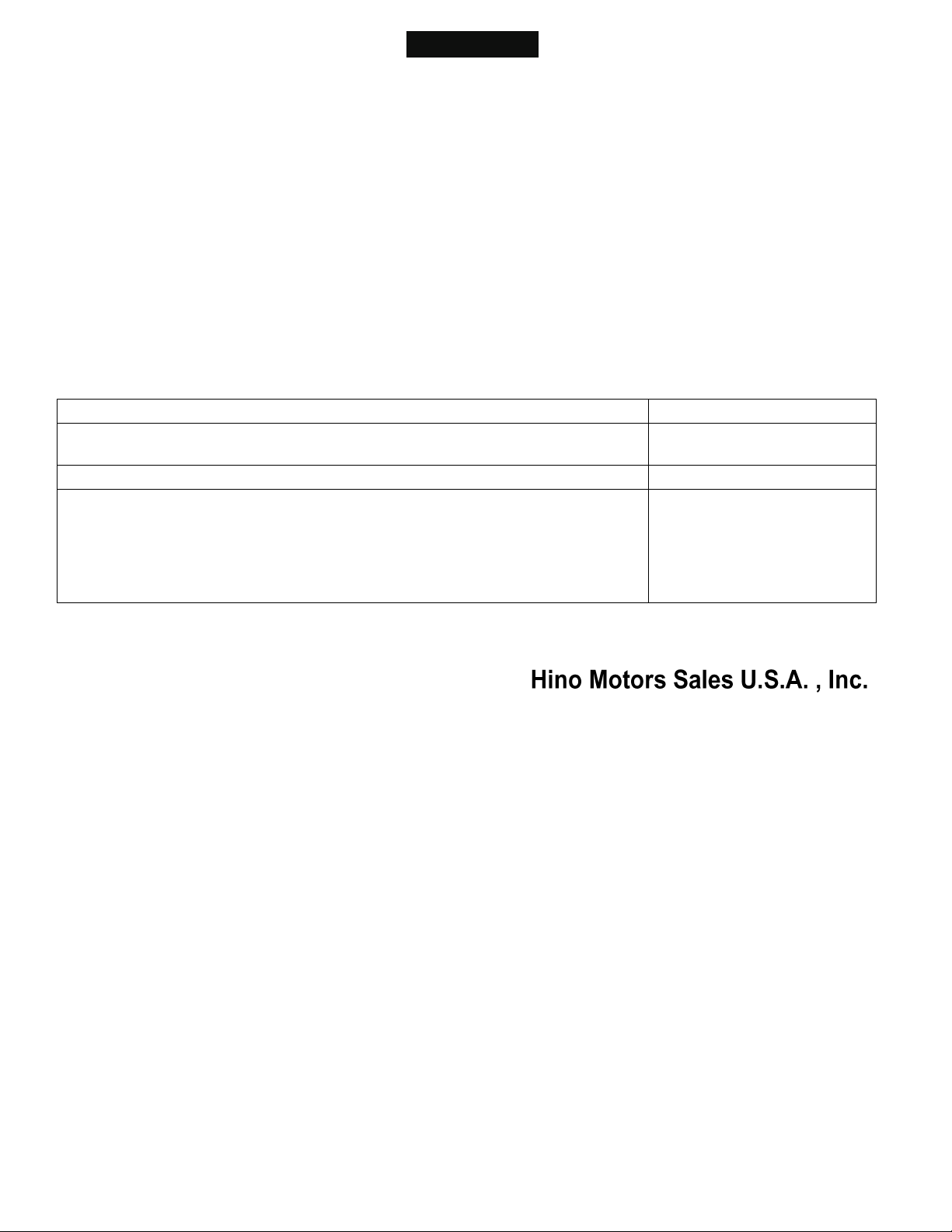
CONFIGURATION DIAGRAM OF HYBRID TROUBLE SHOOTING SYSTEM
HV BATTERY ECU
HV SYSTEM ALARM
HV WARNING LIGHT
ENGINE ECU
VEHICLE CONTROL ECU
CLUTCH ECU
MIL
HV ECU OR COMMUNICATION
FUNCTION PERFORM
ALARMING ONLY WHEN THE
FUNCTION FAILS.
INVERTER
MALFUNCTION INFORMATION
MIL ON REQUEST
MALFUNCTION INFORMATION
MIL ON REQUEST
MALFUNCTION
INFORMATION
MIL ON
REQUEST
MIL ON REQUEST
HV ECU
READ CODE AND
DIAGNOSE
READ CODE AND DIAGNOSE
READ CODE AND
DIAGNOSE
SERVICE TOOL
HYBRID CONTROL SYSTEM:
CAN:
SIGNAL LINE:
SHTS03ZZZ0300001
HYBRID/TROUBLE SHOOTING 3–5
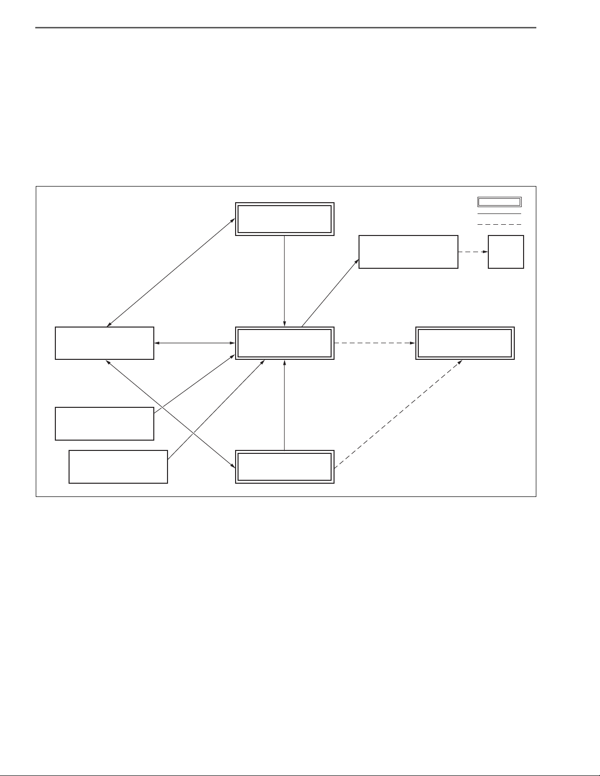
1. HV WARNING LIGHT LIGHTING PROCESS
(1) The HV ECU controls the HV warning light.
(2) The HV warning light turns on in case of malfunction of the HV ECU, the HV battery ECU, the inverter, or the
clutch ECU.
(3) The HV ECU receives information regarding malfunction of the HV battery ECU, the inverter, and the clutch ECU
via CAN.
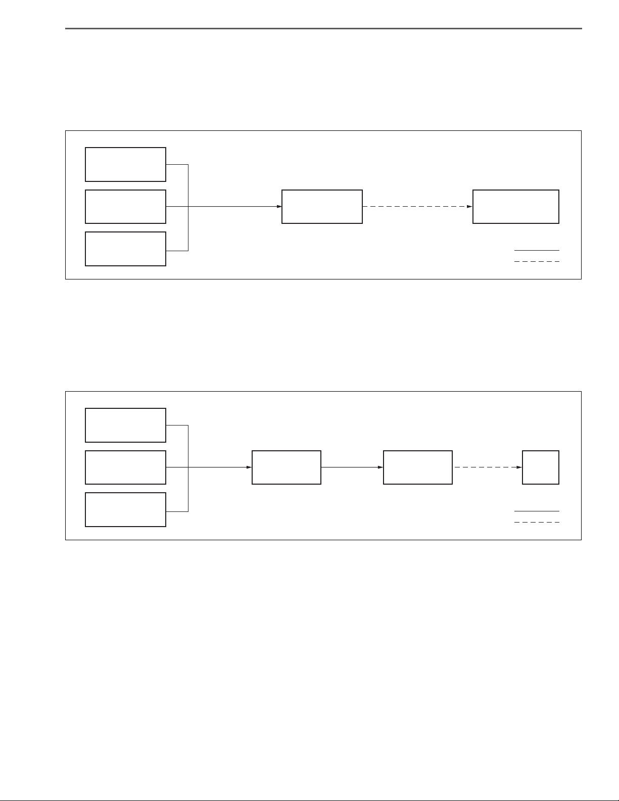
2. ABOUT MIL
(1) The engine ECU controls whether to turn on or turn off MIL.
(2) When a malfunction relevant to emission occurs in the HV system or vehicle control ECU, the MIL light ON
request is sent from the HV ECU to the engine ECU using CAN.
(3) HV battery ECU, inverter and vehicle control ECU send the MIL light ON request to the engine ECU using CAN
via HV ECU.
LIGHT ON OR LIGHT OFF
HV WARNING LIGHT
HV ECU
MALFUNCTION
INFORMATION
HV BATTERY ECU
INVERTER
CLUTCH ECU CAN:
SIGNAL LINE:
SHTS03ZZZ0300002
LIGHT ON OR
LIGHT OFF MIL
HV ECU
MIL ON
REQUEST
ENGINE ECU
MIL ON
REQUEST
HV BATTERY ECU
INVERTER
VEHICLE CONTROL
ECU CAN:
SIGNAL LINE:
SHTS03ZZZ0300003
HYBRID/TROUBLE SHOOTING3–6
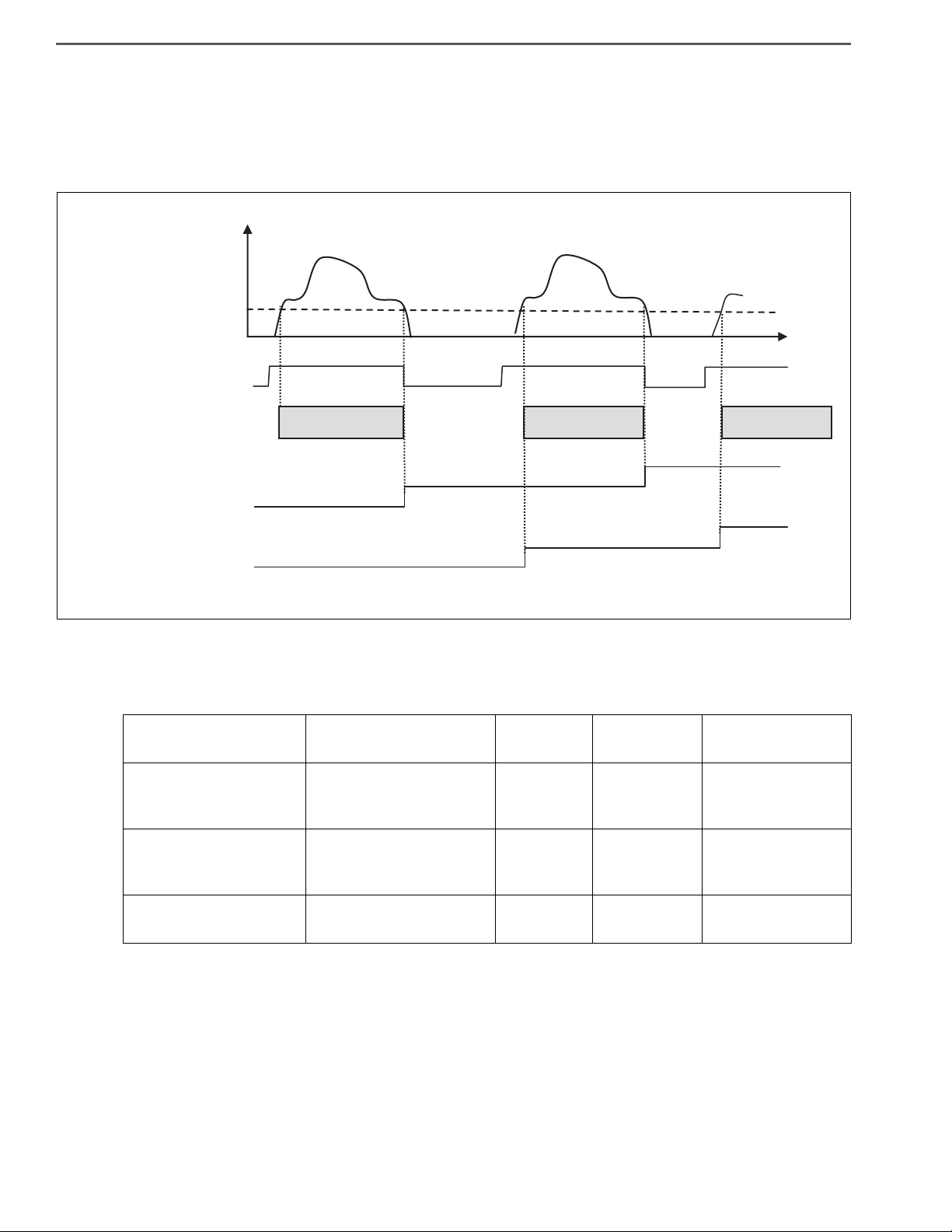
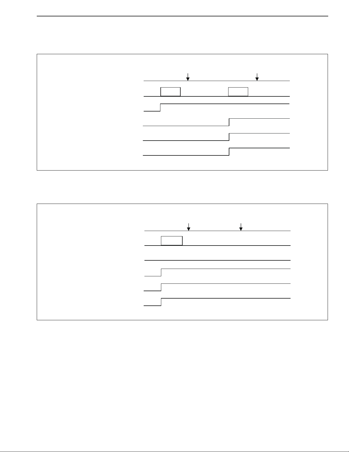
3. DEFINITION OF MALFUNCTION
(1) Driving cycle
The driving cycle (hereinafter referred to as "DCY") is confirmed when the engine revolution becomes equal to or
more than the value calculated using the following formula [idling speed minus 150 r/min] after the starter key is
turned to the "ON" position. DCY is completed when the starter key is turned to the "LOCK" position.
* Completion of DCY is the timing to delete the Permanent diagnosis code and Pending diagnosis code.
(2) Definition of diagnosis code
The following table shows malfunctions that are displayed on the service tool.
*1 This light lights for malfunctions relevant to emission.
*2 If a malfunction is recovered, control is switched from failsafe control to normal control; however the
Confirmed diagnosis code is not deleted.
Code name Definition of diagnosis
code
HV warning
light MIL Effect on vehicle
Pending diagnosis code
Diagnosis code that is
being detected (malfunc-
tion is not confirmed).
Light OFF Light OFF Normal control
Confirmed diagnosis
code
Diagnosis code in which
the malfunction is con-
firmed
Light ON Light ON *1 Failsafe control *2
Permanent diagnosis
code Stored diagnosis code Light OFF Light OFF Normal control
DCY#3
CONFIRMATION TIME
t
COMPLETION
OF DCY#2
COMPLETION
OF DCY#2
COMPLETION
OF DCY#1
COMPLETION OF
DCY#1
DCY#1
CONFIRMATION TIME
DCY#2
CONFIRMATION TIME
ON
LOCK
[r/min]
IDLING SPEED-150 [r/min]
COMPLETION OF
HV BATTERY ECU DCY
COMPLETION OF
INVERTER DCY
STARTER KEY
DCY
COMPLETION OF
HV ECU DCY
ENGINE
SPEED
0
0
0
SHTS03ZZZ0300004
HYBRID/TROUBLE SHOOTING 3–7
(3) Pending diagnosis code
Represents the diagnosis code in which the malfunction is confirmed by detecting the malfunction in 2DCY or
more. The following table shows examples in which the malfunction is confirmed in 2DCY.
(4) Confirmed diagnosis code
Represents the diagnosis code in which the malfunction is confirmed by detecting the malfunction in 1DCY.
*1 For the malfunction in which the Confirmed malfunction is confirmed in DCY, the Pending malfunction
is not confirmed.
COMPLETION OF
DCY#1
COMPLETION OF
DCY#2
DETECTION OF
MALFUNCTION
CONFIRMATION
DETECTION OF
MALFUNCTION
CONFIRMATION
LIGHT ON
LIGHT ON
DCY
VEHICLE CONDITION
PENDING MALFUNCTION
CONFIRMED MALFUNCTION
HV WARNING LIGHT
MIL
SHTS03ZZZ0300005
CONFIRMATION
LIGHT ON
LIGHT ON
COMPLETION OF
DCY#1
COMPLETION OF
DCY#2
DETECTION OF
MALFUNCTION
DCY
VEHICLE CONDITION
PENDING MALFUNCTION *1
CONFIRMED MALFUNCTION
HV WARNING LIGHT
MIL
SHTS03ZZZ0300006
HYBRID/TROUBLE SHOOTING3–8
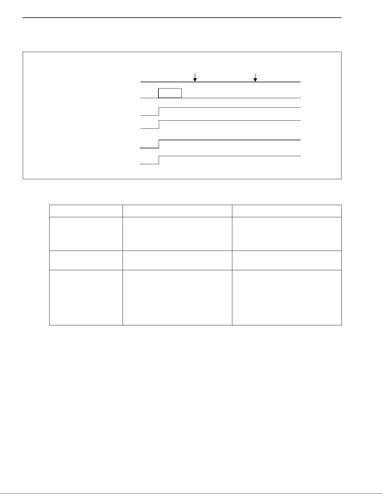
(5) Permanent diagnosis code
Permanent malfunction is confirmed by confirming the Confirmed malfunction.
(6) Deletion of diagnosis code
*1 Refer to the following figure and 4. Procedure for deleting the Permanent malfunction for details.
Code name Deletion from vehicle condition Deletion using the service tool
Pending diagnosis code
This code is deleted when condition
to be judged normal is satisfied and
malfunction detection condition is
not satisfied in 1DCY
Instant deletion
Confirmed diagnosis
code None Instant deletion
Permanent diagnosis
code
This code is deleted when condition
to be judged normal is satisfied in
3DCY. *1
This code is deleted after performing
the predetermined operation when
condition to be judged normal is sat-
isfied and malfunction detection con-
dition is not satisfied in 1DCY after
deleting the diagnosis code using
the service tool. *1
CONFIRMATION
CONFIRMATION
LIGHT ON
LIGHT ON
COMPLETION OF
DCY#1
COMPLETION OF
DCY#2
DETECTION OF
MALFUNCTION
DCY
VEHICLE CONDITION
CONFIRMED MALFUNCTION
PERMANENT MALFUNCTION
HV WARNING LIGHT
MIL
SHTS03ZZZ0300007
HYBRID/TROUBLE SHOOTING 3–9
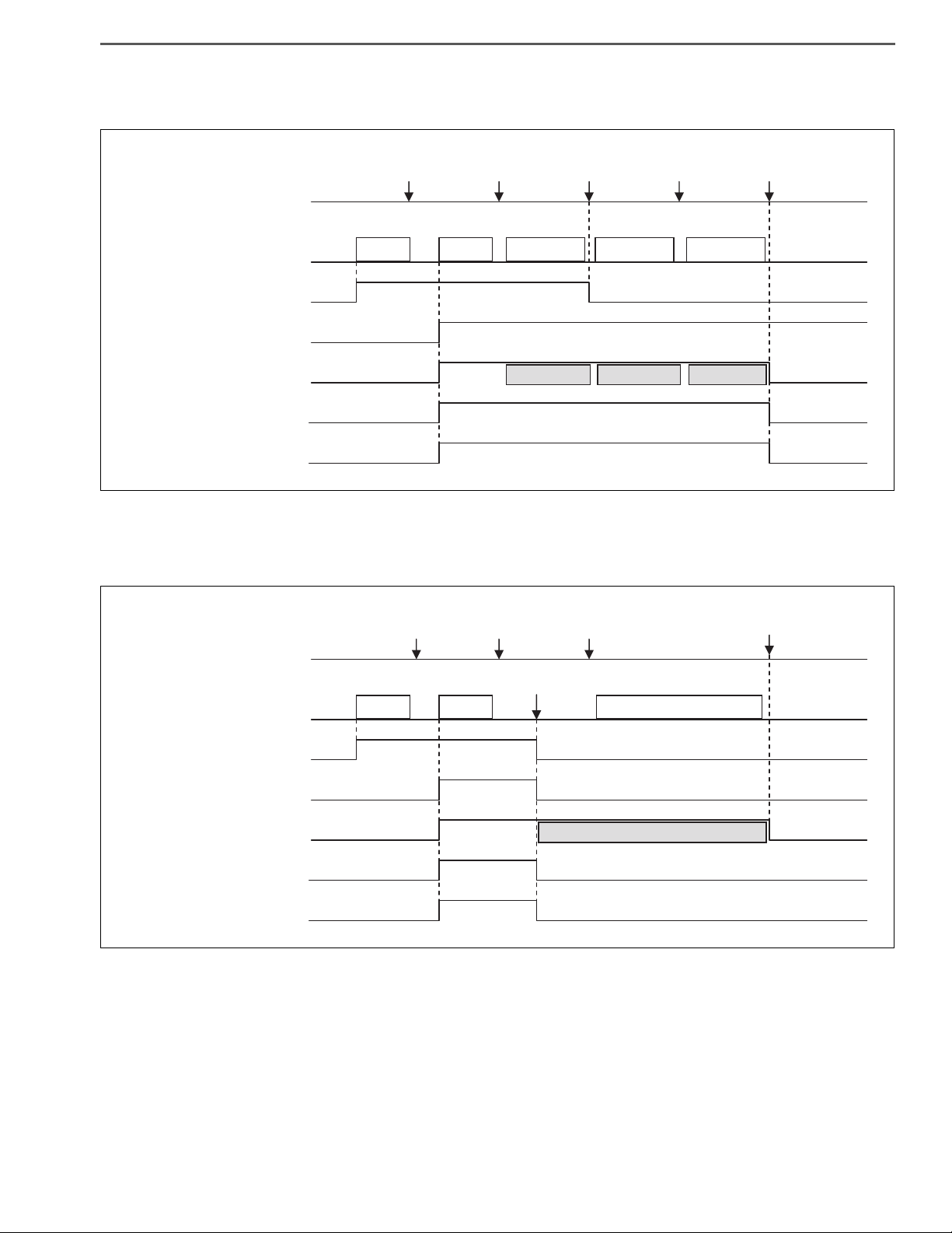
•The following figure shows deletion of the Pending diagnosis code and deletion of the Permanent diagnosis
code in 3DCY.
•The following figure shows clearing of Pending malfunction code, Confirmed malfunction code, and Perma-
nent malfunction code by using the service tool.
*1 Refer to 4. Procedure for deleting the Permanent malfunction (1).
CONFIRMATION
DELETION
DELETION
LIGHT OFF
LIGHT OFF
LIGHT ON
LIGHT ON
CONFIRMATION
CONFIRMATION
COMPLETION OF
DCY#1
COMPLETION OF
DCY#2
COMPLETION OF
DCY#3
COMPLETION OF
DCY#4
COMPLETION OF
DCY#5
DETECTION OF
MALFUNCTION
DETECTION OF
MALFUNCTION
DCY
VEHICLE CONDITION
PENDING MALFUNCTION
CONFIRMED MALFUNCTION
PERMANENT MALFUNCTION
HV WARNING LIGHT
MIL
NORMAL JUDGMENT #1 NORMAL JUDGMENT #2 NORMAL JUDGMENT #3
NORMAL JUDGMENT
DCY#1
NORMAL JUDGMENT
DCY#2
NORMAL JUDGMENT
DCY#3
SHTS03ZZZ0300008
CONFIRMATION
DELETION
DELETION
DELETION
DELETION OF THE MALFUNCTION
CODE USING THE SERVICE TOOL
LIGHT OFF
LIGHT OFF
LIGHT ON
LIGHT ON
CONFIRMATION
CONFIRMATION
COMPLETION OF
DCY#1
COMPLETION OF
DCY#2
COMPLETION OF
DCY#3
COMPLETION OF
DCY#4
DETECTION OF
MALFUNCTION
DETECTION OF
MALFUNCTION
DCY
VEHICLE CONDITION
PENDING MALFUNCTION
CONFIRMED MALFUNCTION
PERMANENT MALFUNCTION
HV WARNING LIGHT
MIL
NORMAL JUDGMENT #1
*1
SHTS03ZZZ0300009

HYBRID/TROUBLE SHOOTING3–10
4. PROCEDURE FOR DELETING THE PERMANENT MALFUNCTION
There are two procedures for deleting the Permanent diagnosis code.
(1) Procedure for deleting the Permanent diagnosis code after deleting the diagnosis code using the service tool
a. Turn the starter key "ON".
b. Delete the diagnosis codes using the service tool.
- Delete diagnosis codes from the following systems.
•ECU of the HV system in which the Permanent diagnosis code is occurring.
(Deletion of engine ECU must be performed after performing deletion in the order of HV battery ECU
Inverter HV ECU.)
•Engine ECU
c. Set the starter key to the "LOCK" position and wait for 30 seconds or more.
d. Turn the starter key "ON".
e. Start the engine.
f. Idle the engine for 6 minutes or more.
g. Keep the engine revolution at 1,150 r/min or more for 6 minutes or longer.
h. Set the starter key to the "LOCK" position and wait for 30 seconds or more.
i. Turn the starter key "ON".
j. Start the engine.
k. Wait for 30 seconds or more.
l. Set the starter key to the "LOCK" position.
! CAUTION
•Trouble shooting the malfunction is conducted before following the above procedure, therefore the malfunction
does not occur or the malfunction does not occur while following the above procedure.
•The HV warning light must turn off when the diagnosis code is deleted at (b).
When the HV warning light turns off, it is possible to check that there is no malfunction in the HV system.
•Condition to be judged normal for the malfunction occurred in the above steps (d) to (g) must be satisfied.
Condition to be judged normal varies depending on malfunction.
(2) Procedure for deleting the Permanent diagnosis code in 3DCY
a. Turn the starter key "ON".
b. Start the engine.
c. Idle the engine for 2 minutes or more.
d. Set the starter key to the "LOCK" position.
e. Wait for 30 seconds or more.
f. Repeat the steps from (a) to (e) for 3 times in total (3DCY).
g. Turn the starter key "ON".
h. Start the engine.
i. Wait for 30 seconds or more.
j. Set the starter key to the "LOCK" position.
! CAUTION
•The above procedure is satisfied when making normal driving operation; therefore the Permanent diagnosis
code may be deleted when making similar driving operation if the malfunction is recovered.
•Trouble shooting the malfunction is conducted before following the above procedure, therefore the malfunction
does not occur or the malfunction does not occur while following the above procedure.
•Condition to be judged normal for the malfunction occurred in the above steps (a) to (d) must be satisfied. Con-
dition to be judged normal varies depending on malfunction.
Confirmed diagnosis code Permanent diagnosis code Deletion procedure
None Present Deletion using the procedure (1)
Present Present Deletion using the procedure (1) or (2)
Present None —

HYBRID/TROUBLE SHOOTING 3–11
5. TROUBLE SHOOTING PROCEDURE
(1) Trouble shooting procedure (when using genuine Hino service tool)
a. Check the DTC of the HV ECU using the service tool (trouble shooting tool).
b. Record the DTC and TC No. (detailed DTC) of freeze frame data.
c. Perform trouble shooting for the relevant DTC. For an inverter/HV battery line malfunction, read the DTC of
each ECU for trouble shooting according to the HV ECU diagnostic chart.
d. After trouble shooting, delete the DTC of each ECU using the service tool and conduct a trial running to check
that the malfunction does not recur.
! CAUTION
•When inspecting the high voltage line, wear insulating gloves because of a risk of electrical shock. Before per-
forming inspection, be sure to remove the service plug after the starter key is turned to the "LOCK" position.
When inspecting the HV battery, wear safety glasses.
Do not touch the terminals of the high voltage line for 7 minutes after removing the service plug.
•One diagnosis code (DTC) may contain more than 1 malfunction. Read TC No. (detailed DTC) of freeze frame
data with the trouble shooting tool and perform trouble shooting according to the relevant trouble shooting
chart.
•When inspecting the harness, first check the connector for fitting looseness, and the fitting surface for entry of
foreign matters.
•There may be irregular contact or temporary noise due to partial fitting of the connector if parts are returned to
normal without repairing or replacing parts using the diagnostic chart.
•The service tool or trouble shooting tool described in the trouble shooting chart indicates the genuine Hino ser-
vice tool.
•If the starter key is turned "ON" in the state that connectors, etc. are disconnected while performing the trouble
shooting chart, the malfunction may be recorded due to disconnection of a connector. In such case, be sure to
delete the diagnosis code using the trouble shooting tool.
HINT
If there is no malfunction and the engine does not stop with the idling stop function, the following cases are con-
ceivable.
•A vehicle is not running at vehicle speed of 5 km/h or more from the last idling stop.
•The change lever is located at a position other than "D" and "4".
•When the turn signal light and the hazard light are ON. (Even if the turn signal light switch signal and the hazard
light switch signal transmitted to the HV ECU are Low, the engine does not stop automatically by use of the
idling stop function.)
•When a vehicle stopped on a sloped road.
•While PTO is operating.
•While DPR is operating.
•Capacity of the HV battery is low.
•Engine coolant temperature is low.
•The engine is still running. (The engine is running at approximately 1 km/h or more.)
•When the status of the idling stop cancel switch is "ON".
•Brake vacuum pressure is low. (Even if the low brake vacuum pressure switch signal transmitted to the HV ECU
becomes Low, the engine does not stop automatically by use of the idling stop function.)
HYBRID/TROUBLE SHOOTING3–12
SAFETY MEASURES FOR HIGH-VOLTAGE
WORK
EN01H03ZZZ030602002002
1. CAUTIONS ON INSPECTION OF HYBRID CONTROL SYSTEM
(1) To inspect the high-voltage system or disconnect the low-
voltage connector in the PCU box, be sure to take actions to
prevent electric shocks, i.e. wearing insulated gloves and dis-
connection of service plug. Removed service plug should be
put in a pocket so as to prevent other engineers from using it
by mistake during work.
!WARNING
Note that the SMR is turned "ON" and high-voltage circuit is acti-
vated when the starter key is turned to "ON."
!CAUTION
Since any failure may occur when the starter key is turned to "ON"
with the service plug removed, never turn the starter key to "ON"
unless otherwise instructed in this document.
(2) All wire harness connectors for the high-voltage circuit are
orange colored. Further, "HIGH VOLTAGE" caution label is
attached to high-voltage components such as the hybrid bat-
tery. Do not touch these wiring and components unnecessar-
ily.
(3) Turn the starter key "LOCK" and remove the service plug.
Then wait for at least 7 minutes before starting the work.
NOTICE
In the 7 minutes the high-voltage capacitor in the inverter dis-
charges.
1
2
3
SHTS03ZZZ0300010

HYBRID/TROUBLE SHOOTING 3–13
(4) Check the insulated gloves for damage such as cracks and
break before use. Also, do not use wet insulated gloves.
(5) Do not carry on any metal product such as a pen and scale
which may fall to cause short circuit while working.
(6) Be sure to wear insulated gloves when it is necessary to
touch any high-voltage terminal without insulating coating.
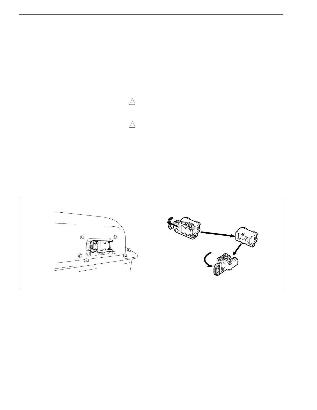
(7) After disconnecting high-voltage connectors and terminals,
insulate them with insulator tape without delay.
(8) After working on high-voltage components, check for any
component or tool left, tightening condition of high-voltage
terminals and connector conditions again before connecting
the service plug.
(9) Do not reserve the hybrid battery.
(10) Do not disassemble the hybrid battery.
! CAUTION
High voltage is applied to the hybrid battery even when the ser-
vice plug is disconnected. Further, high-alkaline electrolyte is
used.
(11) Make sure to use the insulated tools.
Recommended tools: FACON's Facom-quality insulated tools
(12) Turn the starter key to "LOCK" for resistance inspection.
(13) Turn the starter key to "LOCK" before removing/installing
connectors.
(14) Alert other workers with indication such as "High-voltage
work. Don't touch" on the vehicle during works on high-volt-
age components.
(The next page is an example of the indication. You may copy
and use it.)
INCORRECT
SHTS03ZZZ0300011

HYBRID/TROUBLE SHOOTING3–14
SHTS03ZZZ0300012

HYBRID/TROUBLE SHOOTING 3–15
LIST OF CONNECTOR SYMBOLS
EN01H03ZZZ030602002003
WHITE
WHITE
ORANGE
BLACK
BLACK
BLACK
DARK GRAY
WHITE
WHITE
WHITE
1
3
2
23
456789
11112
23
16
22
15
21
14
20
13
24
17
25
18
26
19
10
1
9 10111213141516
2345678
1
12 13 14 15 16 17 18 19 20 21 22
10 1123456789
1
5
23
67
4
8
11 12 13 14 15 16 17 18 19
23456789
20
2423 25 26 27 28 29
21 22
30
110
1234
1234
56789 10 11
30 31
12131415
1617181920
2122232425 26272829
3233343536 37383940
78910
11 12
34
13 14 15 16
17 18 19 20 21 22 23 24
12 56
1819
20 21 22 23 24 25 26
7 8 9 1011121314151617
123456
BATTERY ECU (CAN)A
B
F
GJ/C DIAG CAN
INVERTER COOLING WATER PUMP
BATTERY ECU (TEMPERATURE MONITORING)
CHHV ECU1
BATTERY ECU (VOLTAGE MONITORING)
DIHV ECU2
INVERTER
EJHV ECU3
INVERTER COOLING RADIATOR FAN
SHTS03ZZZ0300013

HYBRID/TROUBLE SHOOTING3–16
123456
16 17
78910
12 13 14 15 18 19 20 21
11
22
12 11 10
1
65
78
9
234
10 11 12
234
5678
9
1
21
17 16
34567
8
101112131415
181920212223
9
24
3456789
101112131415
1819 20 2122 2324
2
17
1
16
21
1234
12
34
GRAY BLACK
WHITE
(RELAY BLOCK SIDE)
BLACK
BLACK BLACK
BLACK
WHITE
WHITE
BLACK BLACK
1234
5678
9 101112
13 14 15 16
4321
8765
12 11 10 9
16 15 14 13
(RELAY BLOCK SIDE)
(COMPONENT SIDE)
(COMPONENT SIDE)
3
5
L
N
2
1
3
5
2
1
12
INVERTER START RELAY
L
NHV BATTERY START RELAY
O J/C CTRL CAN
P PCU HARNESS 16-PIN
RHV BATTERY COOLING FAN
SSMR DRIVE
SERVICE PLUG SWITCH
T
X PCU HARNESS 24-PIN
KCOOLANT TEMPERATURE SENSOR
PCU HARNESS 12-PINY
SHTS03ZZZ0300014
Other manuals for Series 155
1
This manual suits for next models
3
Table of contents
Other Hino Truck manuals


Popular Truck manuals by other brands


Armorgard
Armorgard rubble truck RT400 Operational And Maintenance Manual

Haklift
Haklift HAVA2500V Operation and installation manual

BACKSAFE
BACKSAFE STUGO 16810010 instruction manual

Daewoo
Daewoo Novus M2SEF manual

Chevrolet
Chevrolet 10 1971 Series Chassis Service Manual

Paccar
Paccar Peterbilt 587 owner's manual