Haklift HAVA2500V Specification sheet

Original instruction manual
Alkuperäisten käyttöohjeiden käännös
Översättning av original bruksanvisning
HAVA2500V
Hand pallet truck with scale
Vaakahaarukkavaunu
Handtruck med våg
Lifting Solutions Group
Axel Johnson International
Haklift Oy
Asessorinkatu 3-7
20780 Kaarina, Finland
Tel. +358 2 511 5511
sales@haklift.com
www.haklift.com
Rev. 20220706

2
Thank you for choosing this hand pallet truck with scale. For your safety and correct operation of the scale, please
read these instructions carefully (with understanding) before using the product. Incorrect use may lead to accidents.
The product shall be assembled, used and maintained only by a competent person. This document must be retained
(available to users) throughout the product’s life cycle.
NOTE: (1) All of the information reported herein is based on data available at the time of printing. The manufacturer
reserves the right to modify its own products at any time without notice and incurring any sanction. It’s
advisable to check for possible updates.
(2) Prior to using this hand pallet truck with scale, the battery of the scale must be charged enough.
1. GENERAL SPECIFICATIONS
Model
Capacity
Graduation
Weighing
accuracy
Fork size
Length
Width over forks
Fork width
HAVA2500V
2500 kg
0,5 kg
± 0,05%
1150 mm
540 mm
160 mm
*Materials and specifications may be subjected to changes without notice.
2. TO ATTACH THE HANDLE TO THE PUMP UNIT (assistant pump part numbers are pointed from the OLD pump
assembly drawing)
2.1 Remove the handle assembly (H100) and insert it into the pump shell’s bracket.
2.2 Remove the coupling axle (P10) from the plastic bag.
2.3 Insert the coupling axle (P10) at one end of the pump shell’s bracket to travel through pump bracket’s and handle
assembly’s (H100) designated holes to fix them together. Please note the position of the holes on the axle (P10). Set
the steel chain assembly (pin+nut on the end of the chain, H09) through the axle (P10) center hole.
2.4 Fix the axle (P10) with the spring pin (P11). The axle must have spring pins fixed on its both ends.
2.5 Operate the handle (H01) to press the pump plunger (P24) and remove the pin (P12).
2.6 Raise the crank link (P41) and place the head of the chain (pin+nut on the end of the chain, H09) into the groove
of the crank link (P41).
3. TO ADJUST THE RELEASE DEVICE (assistant pump part numbers are pointed from the OLD pump assembly
drawing)
On the handle of the pallet truck, you will find the control lever (H06) which can be set in three positions (see fig. 1):
LOWER = to lower the forks; NEUTRAL/DRIVE = to move the load; ASCENT/RAISE = to raise the forks. After
assembling the handle, you can adjust the three positions.
3.1 First tighten the setting screw (P43) on the crank link (P41) until the LOWER position function works (adjust the
nut (P42) accordingly in connection with the setting screw).
3.2 If the forks elevate while pumping in the NEUTRAL/DRIVE position, turn the setting screw (P43) clockwise until
pumping the handle does not raise the forks and the NEUTRAL/DRIVE position functions correctly.
3.3 If the forks descend while pumping in the NEUTRAL/DRIVE position, turn the setting screw (P43)
counterclockwise until the forks do not lower.
3.4 If the forks do not descend when the control lever (H06) is in the LOWER position, turn the setting screw (P43)
clockwise until raising the control lever (H06) lowers the forks. Then check the NEUTRAL/DRIVE position as per
item 3.2 and 3.3.
3.5 If the forks do not lift while pumping in the ASCENT/RAISE position, turn the setting screw (P43) counterclockwise
until the forks elevate while pumping in the ASCENT/RAISE position. Then check the NEUTRAL/DRIVE and
LOWER positions as per item 3.2, 3.3 and 3.4.

3
4. MAINTENANCE
4.1 OIL
Please check the oil level every six months. Total oil amount is about 260 ml. In optimum/normal conditions (no
leakage problem) there shouldn’t be any need to add oil. However, it’s important to pay attention to the correct oil
level in order to ensure correct and safe operation of the hand pallet truck. If needed, add injection oil the necessary
amount – this must be conducted with the forks in the lowered position. Also, if necessary, find out the root cause
of the lack of oil. The adding location is circled in blue in below pictures. Add or change the hydraulic oil according
to the table below.
Temperature
Oil
-20℃ ~ +40℃
L-HV46 Hydraulic oil

4
4.2 HOW TO EXPEL AIR FROM THE PUMP UNIT
Air may enter the unit when the seals are replaced. Lift the control lever (H06) to the LOWER position, then move
the handle up and down for several times.
4.3 DAILY CHECK, INSPECTIONS AND MAINTENANCE
Daily check of the pallet truck is necessary to improve safety and to detect wear and tear of the unit in time. Pay
special attention to the wheels, axles, handle assembly, forks and lift/lower control. The type/ID label must always
be clearly legible. Check the product for visible signs of damage and leaks before every use. Do not use a defective
pallet truck – remove it from service immediately and turn to a competent specialist. In addition, a thorough
inspection of the product shall be conducted and recorded on a regular basis (at least once a year or more frequent
if required by legislation or working conditions) by a competent person. Note the maintenance and upkeep
recording list at the end of this manual to help you with the documentation.
4.4 LUBRICATION
Use motor oil or grease to lubricate all moveable parts.
5. GUIDE TO SAFE OPERATION
For safe operation of the truck, please read all warning signs and instructions here and on the product before using
the hand pallet truck.
5.1 Do not operate the pallet truck unless you are familiar with it and have been trained or authorised to do so.
5.2 Do not operate the pallet truck unless you have checked its condition. Pay special attention to the wheels,
axles, handle assembly, forks and lift/lower control.
5.3 Do not use the pallet truck on sloping ground. It is suitable for use on hard, flat, clean/dry and unobstructed
ground/platform/base. Beware of little rocks or similar which could lead to a wheel breakage, especially if a
loaded pallet truck is steered over such impurities.
5.4 Never place any part of your body in the lifting mechanism or under the forks or load. Do not carry passengers.
5.5 The operator should wear gloves and safety shoes for protection.
5.6 Do not handle unstable or loosely stacked loads. Only palletized cargo should be lifted or moved.
5.7 Do not overload the pallet truck. Beware of dynamic loads.
5.8 Do not subject to unbalanced load, either side to side or along the length of the frame (refer to fig. 2/B).
5.9 The capacity of the truck assumes an evenly distributed load with the centre of the load being at the halfway
point of the length of the forks (refer to fig. 2).
5.10 Make sure that length of the forks matches the length of the pallet.
5.11 Lower the forks to the lowest height when the pallet truck is not being used.
5.12 At other specific conditions or places, the operator should operate the pallet truck carefully.
5.13 Do not modify the pallet truck in anyway: NO self-made welding, grinding, unauthorized/unsuitable spare parts
or adapters etc.
5.14 Do not use the pallet truck in rain or expose it to damp environments. Keep it clean and store it appropriately.
5.15 Always lower the forks carefully, never pull the control lever rapidly.
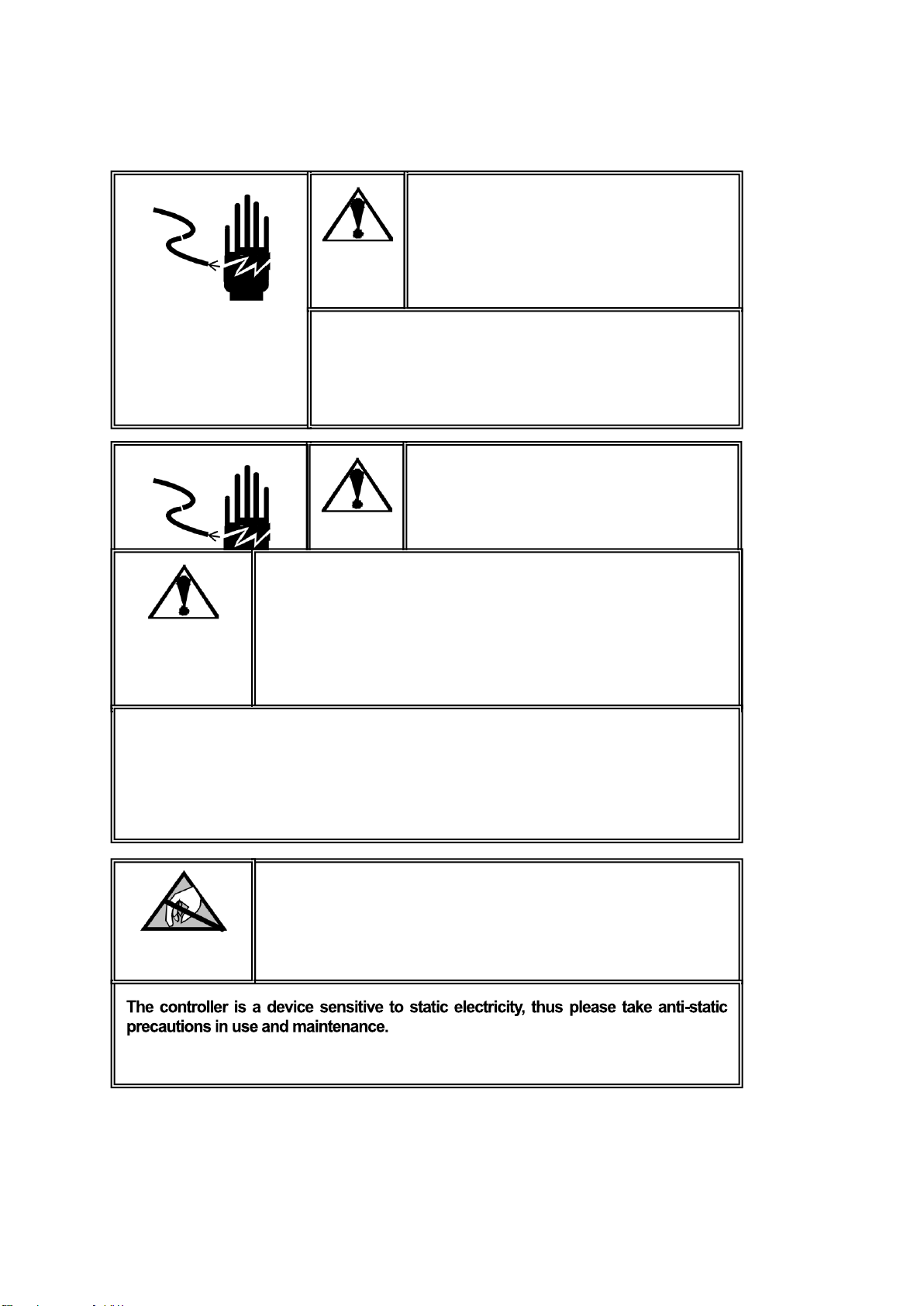
5
6. TROUBLE SHOOTING
NO
TROUBLE
CAUSE
ACTION
1
The forks do not lift
to maximum height.
-Not enough hydraulic oil.
-Add more oil.
2
The forks do not lift
up.
-Not enough hydraulic oil.
-The oil has impurities.
-Discharge valve is out of
adjustment.
-Air in the hydraulic oil.
-Pour in more filtered oil.
-Change the oil.
-Adjust the setting screw (P43).
-Expel the air.
3
The forks do not
descend.
-The rod (P02) and the pump
cover (P101) are deformed
resulting from a seriously
unbalanced load.
-A part has been broken or been
deformed resulting from an
unbalanced load.
-The setting screw (P43) is not in
the correct position.
-Replace the rod (P02) or pump cover
(P101).
-Repair or replace the component.
-Adjust the setting screw (P43).
4
Leaks.
-Seals worn out or damaged.
-Some parts may be cracked or
worn out.
-Replace the seals with new ones.
-Check and replace with new ones.
5
The forks descend
without being
lowered.
-Impurities in the oil cause the
discharge valve (B) to fail to close.
-Air in the oil.
-Seals worn or damaged.
-Discharge valve (B) is out of
adjustment.
-Replace with filtered oil.
-Expel the air.
-Replace with new ones.
-Adjust the setting screw (P43).
*Assistant pump part numbers are pointed from the OLD pump assembly drawing.
7. WEIGHING OPERATION (note: please check the detailed data/functions for the scale from article 11)
7.1 Put the control lever in the LOWER position and lower the truck to lowest position.
7.2 Press the ON/OFF key to turn the system on. After the start-up sequence the indicator will display the weight.
7.3 Weighing method for gross weight:
Press the ZERO key to set the gross weight to 0. Put the forks under the pallet and check that the load is
properly balanced. Put the control lever in the ASCENT/RAISE position, pump the handle to make the forks
rise until the pallet has left the ground. When the indicator is stable, the gross weight of the goods (total weight
of the pallet and the goods) is shown.
7.4 Weighing method for net weight:
To display the weight of the goods without the weight of the pallet (or other container):
7.4.1 Weigh single standard pallet, for example: weight of pallet: 40 kg.
7.4.2 Press the ZERO key, the indicator will display “0 kg”.
7.4.3 Remove the pallet from the forks, the indicator will display “-40 kg”.
7.4.4 Weigh the goods on the pallet as shown in 7.3, when the indicator is stable, the net weight of the
goods is shown.
7.5 Switch between kg and lb: When the weight is shown in kg’s, press on the LB/KG key, unit will thus switch to
pounds. Press on the LB/KG key again and the unit shown will switch back to kg.

6
7.6 Turn off the indicator: Press on the ON/OFF key until the indicator displays “OFF”. Releasing the key will turn
off the indicator. In order to save battery power, turn off the indicator when not in use.
8. BATTERY DATA AND REPLACEMENT
How to change the battery:
1. Loosen the screws on the back of the scale and remove the scale out of its casing carefully.
2. Open the screw on the battery cover and remove the cover. Remove the battery out of the housing (if equipped
with a fastening, release it first) and detach the relevant power plugs.
3. Attach the relevant power plugs and insert the new battery.
4. Screw the battery cover back into position, insert the scale back to its casing and tighten the screws to fix the
scale in place.
Battery type: Rechargeable lead-acid battery.
Capacity: 6V 4Ah/20hr.
Charging time with the original charger: 4 hours to fully charge the battery.
Suggested recharging maintenance when in stock: Once in two months.
Other: Keep the battery sufficiently charged. Charger socket locates below the display unit. Keep the battery clean
and handle it in accordance with good practice.
9. WIRING DIAGRAM OF THE SCALE, JUNCTION BOX AND SENSOR
Instrumentontheback(boxlidopened),wiringdiagram

7
10. TROUBLE SHOOTING OF THE WEIGHING UNIT
NO
TROUBLE
CAUSE
SHOOTING
1
The instrument
shows∶ OVER.
-The load is too big for the scale.
-Remove the load immediately.
2
Text is not printed
clearly on the
ticket.
-Battery voltage is too low.
-Charge the battery.
3
The scale is not
accurate.
-The fork shoe is touching the
bottom part of the scale.
-Cable in the junction box is loose.
-One of the load cells is broken.
-Remove anything that restricts the movement
of the scale.
-Check the connection in the junction box after
confirming safe.
-Stand on the 4 corners of the scale. The load
cell in the corner with a different weight should
be replaced.
4
Indicator can’t be
turned on.
-Battery voltage is too low.
-Battery life is complete.
-Charger is damaged.
-Charge the battery.
-Replace the rechargeable battery with a new
one.
-Check the charger output voltage – replace
the charger with a new one.
5
Battery can’t be
charged.
-Battery is damaged.
-Charger is damaged.
-Replace the rechargeable battery with a new
one.
-Check the charger output voltage – replace
the charger with a new one.
L1~L4 Connect sensor connector
GND
silver
-S
white
+S
green
-E
black
+E
red
L0 Connect meter connector
GND
silver
-S
white
+S
green
-E
black
+E
red

8
10. WEIGHING INDICATOR (FUNCTIONS, CALIBRATION ETC.)
Warning
Ask professional personnel to debug, detect and repair
controller.
Warning
Please keep good grounding of controller.
Warning
In electrical connection of controller, please cut off the power supply in advance.
Wait for 30 seconds between power-on of the controller for 2 times.
Pay Attention to Static Electricity

9
10.1 Technical Indicators
● 6-digit 1.2-inch LED display, 7 state indicator lamps – long service life and shock resistance
● 7 function keys – operation is simple and convenient
● Protection level: IP5x
● Excitation voltage: +5 VDC
● Load capacity of sensor: at most 4 350 Ω simulation sensors
● Input signal range of null point: 0-5 mV
● Input signal range of full scale: 1-10 mV
● Inner resolution: 1 million
● Weight upgrading rate: 40 times per second
● Power supply mode
−Battery: 6 V / 4 Ah
−Adapter: Voltage 100-240 VAC Current 0.1 A Frequency 50-60 Hz.
● 2 RS232 ports
● Operating temperature: -10℃-40℃, relative humidity is below 85 %
● Storage temperature: -20℃-60℃, relative humidity is below 85 %
● Conforming to standard: GB/T 7724-1999
10.2 Main Function
● Basic weighing function: resetting, removing the peel and clearing the peel
● Weight detection function, counting function, animal scale function
● Weight keeping function, weight accumulation function, percentage display
● Set redundant backup function of parameters
● Automatic screen protection and automatic shutdown energy-saving function
● Rich printing formats and communication protocol
10.3 Boundary Dimension
Instrument size: detailed in the following figure (mm); instrument weight: 1.5 kg

10
10.4 Introduction to Panel
● Introduction to indicator lamps
Identifi-
cation
Analysis
Remark
~
Dynamicandstaticindication
Thelamp ison whenscale isindynamic state,
otherwise,thelamp isoff.
Zerocenterindication
Thelamp ison whenthe absolute value ofweightonthe
scaleis less than±0.2d, otherwisethelamp is off.
Net
Identificationofgorsesweight
and net weight
Thelamp ison innetweightand off ingrossweight.
lb
Weightunit
For indicatingcurrentunit.
kg
Hold
Weightmaintenance
Thelamp ison whentheweightis locked,otherwiseitis
off.
Ac
Voltageindicationofbatteryand
powersupply
Thegreenlamp isonwhenthevoltage oftheadapter
and battery is normal, and thered lamp is on in
undervoltagestate.
● Introductionto operationkeys
Operation without special specification refers to short press on keys.
Key symbol
Normal weighing state
Set stage
Weight maintenance key
Short press→ F2.1 = 1, keep/cancel.
F2.1 = 2, switch between percentage and
weight.
F2.1 = 5, switch between quantity and weight.
Long key→ enter setting menu.
Return to the last menu.
Accumulation key
Short key → F2.1 = 4, include display weight in
accumulation value.。
Long key → F2.1 = 3, select scale to sample target
weight.
F2.1 = 4, accumulate weight of scale display.
F2.1 = 5, count sampling of scale.
No definition.
Unit conversion key
Short key → in weighing state, switch weight unit. The
corresponding unit indication lamp is on.
Flicker bit is on the left.
Skin removal key
Short key → net weight turns to gross weight; induction
lamp of net weight “Net” is off.
Flicker bit is on the right.

11
Skin removal key
Short key →gross weight turns to net weight. Indication
lamp of net weight “Net” is on. Conduct skin removal
operation for multiple times.
Digit flicker position reduces.
Zero clearing key
Gross weight state resets weight. When the scale is in
net weight, dynamic state, saving state and out of
resetting range, zero clearing operation is invalid.
In setting, digit of flicker
position increases. In
adjustment of display,
accumulation is cleared.
Printing key
Short key → start up or print.
Printing format refers to Appendix1.
Long key → shut down.
Confirm operation, to save
setting data.
10.5 Parameter Setting
Setting entry:
Press the [Hold] button on the operating panel in the state of normal weighing.
If F1.14 = 0, you can set all the parameters within F1~F5.
If F1.14 = 1, you can only set all parameters within F2~F5.
If F1.14 = 1 and you need to set the parameters within F1 menu, you can press the calibration switch
button until the F1 menu is entered.
F1 Parameter Setting of Scale
F1.1 Measuring Range
Selectable parameters: 3~200000 (default value: 6)
F1.2 Decimal Places
Selectable parameters: 0 ---- no decimal point
0.0 ---- 1 decimal place
0.00 ---- 2 decimal places
0.000 ---- 3 decimal places (default value)
0.0000 ---- 4 decimal places
F1.3 Number of Divisions
Selectable parameters: 1 (default value), 2, 5, 10, 20, 50
F1.4 Calibration Unit
Selectable parameters: 0 ---- kg (default value)
1 ---- lb

12
F1.5 Gravitational Acceleration
Selectable parameters: 9.70000~9.99999. Default value = 9.79455.
F1.6 Null-point Calibration
【 】 Keeping empty the scale
Remove the weights on the weighing platform to guarantee the scale is in
the empty state. Press the [Print] key and the meter will display [ ].
The displayed digits will reduce slowly until the meter displays [ ].
In the end it will display [ ] for one second, which indicates the end
of null-point calibration.
F1.7 Load-point Calibration
【 】 Loading weights
Load weights on the weighing platform to ensure that 10 % of full-scale value ≤ weight of weights ≤ full-scale value,
and then press the [Print] key to start the next step.
【 】 Entering the same weight value as that of the loaded weights.
Entering the same weight value as that of the loaded weights, please press the
[Print] key after the scale becomes stable, and the meter will display [ ].
After that, the displayed digits will reduce slowly until the meter displays
[ ]. In the end it will display [ ] for one second, which indicates the
end of null-point calibration.
F1.8 Automatic Null Tracking
Selectable parameters: OFF, 1 d, 2 d, 3 d (default value)
F1.9 AutomaticResetRangeatStartup
Selectable parameters: OFF, 2%, 10 %,20%(defaultvalue)
F1.10 Button Reset Range
Selectable parameters: OFF, 2%, 10 %(defaultvalue),20 %
F1.11 Digital Filter
Selectable parameters: 0 ---- Mild Filtering
1 ---- Moderate Filtering (default value)
2 ---- Severe Filtering
F1.12 Steady Range
Selectable parameters: 1 d, 2 d, 3 d (default value)
F1.13 Overload Display Range
Selectable Parameters: 9 d, 5 % (default value), 10 %, 20 %
F1.14 F1 Menu Protection
Selectable Parameters: 0 ---- Enter F1 menu by keyboard operation
1 ---- Enter F1 menu by pressing the calibration button

13
F1.15 Restoring Factory Default
Set the parameters within F1~F4 as the defaults, which can’t impact the parameters of standard scale.
F2 Application Function Setting
F2.1 Function Selection
Selectable Parameters: 0 ---- Close the application functions (default value)
1 ---- Weight keeping function
2 ---- Percentage display function
3 ---- Weight checking and sorting function
4 ---- Accumulative scale function
5 ---- Counting scale function
6 ---- Animal scale function
F2.2 Empty-scalethresholdvalue
Selectable Parameters: 0~ fullrange(defaultvalue:0.001)
F2.3 Target Weight for Weight Checking and Sorting
Selectable Parameters: 0~ fullrange(defaultvalue:2.000)
F2.4 Positive Error for Weight Checking and Sorting
Selectable Parameters: 0~ fullrange(defaultvalue:0.100)
F2.5 Negative Error for Weight Checking and Sorting
Selectable Parameters: 0~ fullrange(defaultvalue:0.100)
F2.6 Access to Target Weight for Weight Checking and Sorting, and Counting Sample Weight
Selectable Parameters: 0 ---- Access to Platform Weighing (default value)
1 ---- Manual Input Access
F3 Energy-saving Parameter Setting
F3.1 Time-out Screensaver Time Setting
Selectable Parameters: 0~ 99 minutes, (default value: 30 minutes)
If set to be 0, this function shall not be allowed.
During the screen protection, the display will randomly show “ ”.
F3.2 Energy-saving Time Setting for Auto Power-off
Settable Parameters: 0~250 minutes. (default value: 150 minutes)
If set to be 0, this function shall not be allowed.
F3.3 Display Brightness Control
Selectable Parameters: 0---- low light level
1 ---- middle light level (default value)

14
2 ---- high light level
F4 Serial-port Setting
F4.1 Setting of UART0 Communication Interface Parameter
F4.1.1 Communication Mode
Selectable Parameters:
0---- no output (default value)
1---- continuous output protocol A
2---- continuous output protocol B
3---- continuous output MT
4---- firm output protocol A
5---- firm output protocol B
6---- key dispatch protocol A
7---- key dispatch protocol B
F4.1.2 Setting of Data and Check Pit
Selectable Parameters: 8_N_1 ---- 8-pit no parity check (default value)
7_E_1 ---- 7-pit odd parity check
7_O_1 ---- 7-pit even parity check
8_E_1 ---- 8-pit odd parity check
8_O_1 ---- 8-pit even parity check
F4.1.3 Baud Rate
Selectable Parameters: 1200, 2400, 4800, 9600 (default value)
F4.1.4 Continuous Output & Delivery Parity Check and Character (only for F4.1=3)
Selectable Parameters: 0 ---- no delivery (default value)
1 ---- delivery
F4.1.5 Bluetooth Node Setting (effective only when Bluetooth module option is configured)
Selectable Parameters: HoLi01~HoLi99 (default value: HoLi01)
F4.2 Parameter Setting of UART1 Printing Interface
F4.2.1 Whether to connect the printer
Selectable Parameters: 0 ---- not connected to the miniprinter (default)
1 ---- connected to the miniprinter
F4.2.2 Printing Carriage Return Character
Selectable Parameters: 0~9 carriage return characters (default value: 3)
F4.2.3 Printing Setting of Accumulative Scale

15
Selectable Parameters: 0 ---- total accumulative data for printing (default value)
1 ---- printing detail + total accumulative data
F5 Maintenance and Service
F5.1 Key test
Instrument display 【 】, press『Print』, 『Zero』, 『Tare』,
『Gross』, 『lb/kg』 and 『Total』 in order, and the instrument displays 【 】, 【 】,
【 】, 【 】, 【 】 and 【 】, press 『Hold』 to quit key test.
F5.2 Display screen test
All strokes of meter display will have self-inspection, to observe whether there is lacks of strokes.
Press 『Hold』 or 『Print』 to quit test of display screen.
F5.3 Display current internal code
The display will show internal code of current instrument after smoothing. Press 『Hold』 or 『Print』
to quit the interface.
10.6 Function Description
● Weight maintenance function F2.1 = 1
Operation method
In normal weighing state, press 『Hold』 on the operation panel, the will instrument lock display
weight of the current scale, and “Hold” indication lamp is on. Only when weight setting value ≥
F2.2 is displayed, weight maintenance operation is effective. Otherwise, it will return to weighing
state after invalid operation information 【 】 is shown for a second.
If weight is in locked state, press 『Hold』 again to cancel locking of weight and return to normal
weighing state, and “Hold” indication lamp is off.
If it is in weight locking state, refuse to remove skin, clear skin and zero setting operation.
● Percentage display F2.1 = 2
Display specification
Display【 】, representing 20.5 %.
Pr = current actual weight / range ×100 %.
Press 『Hold』 to display switch in percentage and weight.
● Check weight and selection scale function F2.1 = 3
Function description
Set parameters such as F2.2 = A, F2.3 = B, F2.4 = C and F2.5 = D.
When display weight is X.
If X ≤ A, do not conduct check weight and selection.
If X < (B – D), it lacks of weight, and the display flickers.
If (B – D) ≤ X ≤ (B – C), it is qualified and the display has normal display
If X > (B – C), it is overweight and the display flickers.
Acquisition of target value
Press 『Total』 long until the display shows【TARGET】, and then press『Print』to show current target
value and flicker.

16
If F2.6 = 0, press 『Print』, the instrument will take the weight on current scale as the new target value
and quit the setting interface.
If F2.6 = 1, the display shows 【 】, to request manual change of target value. After change,
press 『Print』 to save setting data and quit setting interface.
• Function of accumulation scale F2.1 = 4
Operation method
In normal weighing state, when the scale is in zero, add weight to the scale and press『Total』on
operation panel, if the display shows【 】 progress bar, it indicates that the current display
weight is included accumulated value, and then it returns to normal weighing state. If the display
shows【 】 for a second, and returns to the normal weighing state, it indicates operation
is invalid. Reason: 1. Between two accumulation operations, the scale must have back-to-zero
process, otherwise, accumulation is refused. 2. Accumulation operation is effective only when
display weight ≥ F2.2 is set. 3. The scale is in dynamic state.
Adjustment, clearing and printing of accumulated value
In normal weighing state, press 『Total』 on operation panel for more than 2 seconds, the display
will show 【 】 for a second, and then the display shows current total accumulated value
【 】 and flickers. To clear accumulated value, press 『Zero』, to make flicker weight
be 0. Press 『Print』 to print accumulated data. Press 『Hold』 to quit the interface.
Attention: set whether to be over detailed data or accumulated data in F4.6.
• Function of counting scale F2.1 = 5
Instrumentdisplay
【 】,showingcurrentquantity.
Samplingmethod
1. Checkwhetherthescaleisinzero,ifnot,press 『Zero』 for zero setting.
2. Place materials counted on the scale.
3.Press 『Total』 long until the display shows 【 】, and then press 『Print』. If F2.6 = 0,
the display shows【 】. Input the quantity counted just now, and press 『Print』 for confirmation.
The instrument saves sampling data and quits the sampling interface. If F2.6 = 1, the display shows
【 】, input sample weight. Press 『Print』, the instrument saves setting data and quits sampling
setting interface.
4. In this function, press『Hold』 to display switch between quantity and weight.
• Function of animal scale F2.1 = 6
Operation method
In normal weighing state, place the animal on the weighing platform and its weight must be ≥threshold
value set in F2.2. Press 『Total』, instrument will collect data sampling. After sampling, the average value
of sampling data will be locked, showing A X.XXX. Press『Print』 to print; press 『Hold』 or 『Total』
to quit the interface.
10.7 Prompt Message of Instrument
The instrument has extremely high stability and reliability, thus is not easy to have error in general situation. Once an
error occurs, please make clear the error first and observe whether the instrument still has error after power-on. Do
not hurry to repair the scale body or instrument. Repair the instrument according to error code of the instrument as
possible.

17
No.
Symbol
Analysis
Treatment Method
1
【 】
【 】
Unable to reset after startup
1. Determine it is no-load state in
startup;
2. Make zero calibration again.
2
【 】
The weighed object is over full
range for 9 days
Reduce weight on weighing platform
3
【 】
The weighed object is below 0 for
5 days
Press 『Zero』 to reset
4
【 】
【 】
Out of zero clearing range
Check whether the weighing platform
has weight.
Remove weight.
5
【 】
Invalid operation
6
【 】
EEPROM checksum and error
Press 『Print』 reprint factory value.
Start up again. If the information occurs
again, return to factory for repair.
Please calibrate the scale again if the
situation does not occur;
Attention: this place is provided with all
parameters of instruments of the
factory.
7
【 】
The calibration input weight is too
small
Input ≥ 10 % weight of full range
8
【 】
The weight in calibration is too
light
Load ≥ 10 % weight of full range
9
【 】
The scale is dynamic in scale
Inspect the scale body
10
【 】
Setting error of date and time
Set according to specification of date
and time
11
【 】
Error of AD initialization
If the error occurs after restarting, return
it to the factory for repair
12
【 】
In loading scale, it indicates to
loading weight;
Load weight according to requirements;
13
【 】
It has entered menu setting
Press 『Print』 to continue setting
14
【 】
End of zero point and loading
point calibration
15
【 】
Including current display weight in
accumulated value
16
【 】
Accumulated weight overflows
Clear accumulated weight in time
17
【 】
Loading default value
18
【 】
Printing
Appendix 1. Continuous Output Format Specification
1.Continuousoutput MTformat
ContinuousoutputMTformathas18digits.

18
Continuous output format
STX
A
B
C
X
X
X
X
X
X
X
X
X
X
X
X
C
R
CK
S
1
3
6
6
1
1
Where:
1.<STX>ASCII(02H)
2.Statusword:A,B,C
3.Displayweight,possiblygrossweightornetweight,6digitswithoutsymbolordecimalpoint.
4.Tareweight,6digitswithoutsymbolor decimal point
5.<CR>ASCIIcarriagereturn(ODH)
6、<CKS>optionalchecksumand(nooutputinF4.2.3=0)
Statusword:A,B,C.
Status word A
Bit 0
Bit 1
Bit 2
Position of decimal point
0
1
0
1
0
1
1
0
0
1
0
0
1
1
1
XXXXXX
XXXXX.X
XXXX.XX
XXX.XXX
XX.XXXX
Bit 3
Constant 0
Bit 4
Constant 1
Bit 5
Constant 0
Bit 6
Constant 1
Bit 7
Constant 0/check bit
Status word B
Bits
Function
Bit 0
Gross weight = 0, net weight = 1
Bit 1
Symbol: positive = 0, negative = 1
Bit 2
Overload (upper and lower overload) = 1
Bit 3
Static = 0, dynamic = 1
Bit 4
Constant 1
Bit 5
Constant 1
Bit 6
Constant 0
Bit 7
Constant 0/check bit
Status word C
Bits
Function
Bit 0
Unit: kg = 0, lb = 1
Bit 1
Constant 0
Bit 2
Constant 0
Bit 3
Constant 0
Bit 4
Constant 1
Bit 5
Constant 1
Bit 6
Constant 0
Bit 7
Constant 0/check bit

19
2.Continuousoutput Aformat
Thedatatransmittedbycontinuous outputprotocolAis presentdisplayweight.
Gross weightformat:ww0000.000kgor ww0000.000lb
Netweightformat:wn0000.000kgor wn0000.000lb
Example: gross weight of15.000kg
w
w
0
0
0
1
5
.
0
0
0
k
g
0d
0a
Netweightof 15.000kg
w
n
0
0
0
1
5
.
0
0
0
k
g
0d
0a
Gross weight-15.000kg
w
w
-
0
0
1
5
.
0
0
0
k
g
0d
0a
Note:theabovepositionofthedecimalpointisdeterminedaccordingtothatintheinstrument.
3. ContinuousoutputBformat
ContinuousoutputagreementBformat:
1
2
3
4
5
6
7
8
9
10
11
12
13
14
15
16
17
18
HEAD1,HEAD2, DATA UNIT CR/LF
HEAD1:OL Upperoverloadorloweroverload,ornozeroclearinginstartup;
ST thescaleisinstablestate;
US thescale isinunstablestate;
HEAD2:GS grossweight;
NT netweight;
DATA:instrumentdisplaydata;
UNIT:kgorlb;
CR/LF:newline.
Example1:instalestate,grossweight is18.000kg.sp=space.
S
T
,
G
S
,
sp
sp
1
8
.
0
0
0
k
g
0d
0a
Example2:inunstablestate,netweightis-0.200kg.sp=space.
U
S
,
N
T
,
-
sp
sp
0
.
2
0
0
k
g
0d
0a
Appendix 2. Printing Format Specification
F2.1=0,1,4,6,printcurrentresetting,press『Print』.
REPORT
------------------------
Gross 0.200kg
Tare 0.000kg
Net 0.200kg

20
F2.1= 1weightmaintenance function:
Weight is not in maintenance state: Weight is in maintenance state:
or
F2.1=3selection,checkweight,press 『Print』:
Underweight Qualified Overweight
F2.1= 4accumulationscale,print detailedstatementorformatof totalweight:
Print details and total weight Only print total weight
F2.1=5countingscale,press『Print』:
REPORT
-----------------------
Gross 1.980kg
State Less
REPORT
-----------------------
Gross 2.000kg
State OK
REPORT
-----------------------
Gross 2.020kg
State Over
REPORT
----------------------
Gross 0.547kg
Amount 55
REPORT
----------------------
Gross 25.000kg
Status Hold
REPORT
------------------------
Gross 0.200kg
Tare 0.000kg
Net 0.200kg
REPORT
----------------------
Net 25.000kg
Status Hold
REPORT
-------------------------
1 0.200kg
2 0.175kg
3 0.347kg
4 0.375kg
-------------------------
Total 1.097kg
REPORT
-------------------------
Total 1.097kg
Table of contents
Languages:
Other Haklift Truck manuals