Hinowa LightLift 15.70 3S Installation and operation manual
1
TECHNICAL COURSE BOOKLET
LightLift 15.70 3S
PERFORMANCE
TTLL1570021702

2
INDEX
1. INTRODUCTION.............................................................................................................................6
1.1 PARTS DENOMINATION..............................................................................................................6
1.2 SERIAL NUMBER LOCATION .....................................................................................................8
2. LL15.70 DATA................................................................................................................................. 9
2.2 TECHINCAL SPECIFICATIONS..................................................................................................9
2.3 LL15.70 DIMENSIONS...............................................................................................................11
2.4 LL15.70 WORKING AREA - 230 KG UNRESTRICTED CAPACITY ...............................13
3. MACHINE OPERATIONAL INTRODUCTION ........................................................................14
3.1 MACHINE IGNITION...................................................................................................................14
3.2 STOP BUTTONS............................................................................................................................16
3.3 REMOTE CONTROL FUNCTIONS ............................................................................................16
4. GROUND PART MOVEMENTS ..................................................................................................18
4.1 TRACKS MOVEMENTS................................................................................................................18
4.1.1 TRACKS WIDENING ...........................................................................................................21
4.1.2 TRACKS MOVEMENT SPEED SELECTION ...................................................................21
4.1.3 TRACKS AUTOMATIC SPEED CONTROL .....................................................................22
4.2 OUTRIGGERS MOVEMENTS.....................................................................................................23
4.2.1 AUTOMATIC STABILIZATION .........................................................................................24
4.2.2 OUTRIGGERS AUTO-RETRACTION...............................................................................25
4.2.3 SINGLE OUTRIGGER MOVEMENTS...............................................................................27
5. AERIAL PART MOVEMENTS .....................................................................................................28
5.1 ENGINE CARTER CONTACT PREVENTION SYSTEM........................................................30
6. PEDAL (OPTIONAL) ....................................................................................................................31
7. EMERGENCY OPERATIONS ......................................................................................................32
7.1 EMERGENCY DEVICES AND TOOLS LOCATION...............................................................32
7.2 AERIAL PART EMERGENCY OPERATIONS ..........................................................................34
7.2.1 GRAVITY EMERGENCY DESCENT ......................................................................................35
7.2.2 OPERATIONS FROM GROUND CONTROL POSITION..................................................36
7.2.3 EMERGENCY DESCENT WITH SAFETIES BY-PASS .....................................................37
7.2.4 EMERGENCY DESCENT FROM THE GROUND WITH HAND PUMP.......................... 38
7.3 GROUND PART EMERGENCY MOVEMENTS........................................................................40
7.3.1 TRACKS MOVEMENT WITH SAFETIES BY-PASS..........................................................40
7.3.2 OUTRIGGERS MOVEMENT WITH THE HAND PUMP....................................................41

3
7.4 ENGINE EMERGENCY START PROCEDURE ........................................................................44
7.4.1 GASOLINE –HONDA iGX390 EMERGENCY START.....................................................45
7.4.2 DIESEL - HATZ 1B40 EMERGENCY START ....................................................................46
8. HYDRAULIC SYSTEM..................................................................................................................47
8.1 MAIN COMPONENTS IDENTIFICATION AND LOCATION ..............................................47
8.2 HYDRAULIC DIAGRAM...............................................................................................................49
8.2.1 HYDRAULIC DIAGRAM INDEX ............................................................................................ 49
8.2.2 PUMPS AND UNDERCARRIAGE PART HYDRAULIC DIAGRAM.................................50
8.2.3 AERIAL PART HYDRAULIC DIAGRAM...............................................................................51
8.3 PUMPS AND HYDRAULIC LINES SYSTEM...........................................................................52
8.4 GROUND PART HYDRAULIC SYSTEM...................................................................................55
8.4.1 OUTRIGGERS............................................................................................................................56
8.4.2 DRIVE GEAR MOTORS...........................................................................................................57
8.4.3 TRACKS WIDENING ...............................................................................................................59
8.5 AERIAL PART HYDRAULIC SYSTEM......................................................................................60
8.5.1 FIRST AND SECOND BOOMS.............................................................................................. 61
8.5.2 THIRD BOOM ............................................................................................................................62
8.5.3 TELESCOPE................................................................................................................................62
8.5.4 JIB.................................................................................................................................................62
8.5.5 BASKET LEVELING..................................................................................................................62
8.5.6 BASKET ROTATION ................................................................................................................62
8.5.7 TURRET ROTATION ................................................................................................................63
8.5.8 EMERGENCY GRAVITY DESCENT SYSTEM.....................................................................63
9. ELECTRICAL SYSTEM.................................................................................................................64
9.1 ELECTRONIC BOARDS INTRODUCTION AND LOCATION.............................................64
9.2 SOFTWARE ....................................................................................................................................65
9.3 CAN-BUS SYSTEM.......................................................................................................................65
9.4 SENSORS COMMUNICATING THROUGH CAN-BUS ........................................................66
9.5 SENSORS AND DEVICES NOT COMMUNICATING THROUGH CAN-BUS.................68
9.6 INCLINATION SENSOR SYSTEM............................................................................................73
9.7 LOAD CELL SYSTEM ...................................................................................................................73
9.8 ELECTRIC MOTOR (NOT FOR LITHIUM VERSION) .........................................................74
9.9 12 VOLT BATTERY.......................................................................................................................75
9.10 BATTERY CHARGE SYSTEM .................................................................................................75

4
10. DIAGNOSE AND SETTINGS.....................................................................................................76
10.1 DIAGNOSE AND SETTINGS BY REMOTE CONTROL ...................................................76
10.1.1 DISPLAY ICONS ...................................................................................................................76
10.1.2 INPUT.......................................................................................................................................78
10.1.3 LANGUAGE.............................................................................................................................85
10.1.4 ERRORS ..................................................................................................................................86
10.1.5 RAMPS .....................................................................................................................................87
10.1.6 CURRENTS .............................................................................................................................87
10.1.7 WORKING HOURS...............................................................................................................88
10.1.8 JOYSTICK ...............................................................................................................................88
10.1.9 SETUP ......................................................................................................................................88
10.1.9.1 ROTATION..........................................................................................................................89
10.1.9.2 VERSION.............................................................................................................................89
10.1.9.3 TIME .....................................................................................................................................89
10.1.9.4 PASSWORD........................................................................................................................89
10.1.9.5 DATE ....................................................................................................................................89
10.1.9.6 LOAD SENSOR..................................................................................................................90
10.1.9.7 INCLINATION SENSOR..................................................................................................90
10.1.9.8 EXTRA..................................................................................................................................90
10.1.9.8.1 FIRMWARE.....................................................................................................................90
10.1.9.8.2 CARDS............................................................................................................................. 90
10.1.9.8.3 MODEM............................................................................................................................91
10.1.9.8.4 GPS...................................................................................................................................91
10.1.9.8.5 OPTIONAL (PAGE1) ....................................................................................................91
10.1.9.8.5.1 PEDAL ..........................................................................................................................91
10.1.9.8.5.2 BEEPER........................................................................................................................92
10.1.9.8.5.3 SECOND SPEED .......................................................................................................92
10.1.9.8.5.4 ELECTRIC MOTOR ...................................................................................................92
10.1.9.8.5.5 LAMPS..........................................................................................................................92
10.1.9.8.5.6 CHK INC......................................................................................................................92
10.1.9.8.6 OPTIONAL (PAGE 2)...................................................................................................93
10.1.9.8.6.1 SERVICE .....................................................................................................................93
10.1.9.8.6.2 RC SPEED...................................................................................................................93
10.1.9.8.6.3 RC MOVE ....................................................................................................................93

5
10.1.9.8.6.4 AD TEST...................................................................................................................... 93
10.1.9.8.6.5 AS TEST ......................................................................................................................93
10.1.9.8.6.6 SKYGUARD.................................................................................................................94
10.1.9.8.7 OPTIONAL (PAGE 3)...................................................................................................94
10.1.9.8.7.1 CHG SET .....................................................................................................................94
10.1.9.8.7.2 INV SET.......................................................................................................................94
10.2 REMOTE CONTROL CONNECTION ON THE GROUND CONNECTOR .....................95
11. POWER SYSTEM...........................................................................................................................97
11.1 GASOLINE MACHINE WITH ENGINE HONDA IGX390.....................................................99
11.2 DIESEL MACHINE WITH ENGINE HATZ 1B40 ............................................................101
11.3 LITHIUM MACHINE WITH 36V LITHIUM BATTERY SYSTEM......................................103
APPENDIX 1 –TILT SENSOR CALIBRATION...............................................................................109
APPENDIX 2 - LOAD CELL BOARD (ECM3) CALIBRATION ....................................................110
APPENDIX 3 - REMOTE CONTROL JOYSTICK CALIBRATION................................................111
APPENDIX 4 –REMOTE CONTROL STOP BUTTON BY-PASS ................................................112
APPENDIX 5 –PHOTOCELLS SETTING AND CALIBRATION..................................................113
APPENDIX 6 –MASTER BOARD (ECM1) REPLACEMENT AND SETTING ..........................114
APPENDIX 7 –ACOUSTIC RECALL DEVICES..............................................................................117
APPENDIX 8 –SKYGUARD.................................................................................................................118
APPENDIX 9 –CODE MENU...............................................................................................................119
APPENDIX 10 - TROUBLESHOOTING ............................................................................................125
APPENDIX 11 –INPUT MENU OLDER THAN RELEASE 2.0 ....................................................132

6
THE PRESENT MANUAL HAS TO BE CONTEMPLATE WITH INDICATIVE
PURPOSE, IT DOESN'T REPLACE ANYHOW MACHINE USE AND
MAINTENANCE MANUAL.
UNANNOUNCED VARIATIONS AND CORRECTIONS COULD BE APPLIED
ON MACHINES AND ON THE PRESENT DOCUMENT.
THEREFORE ALWAYS REFER TO USE AND MAINTENANCE MANUAL FOR
ORDINARY AND EXTRAORDINARY USAGE, FOR MAINTENANCE, FOR
PROBLEM SOLVING AND GENERALLY FOR ANYTHING REGARDING THE
MACHINE.
1. INTRODUCTION
This booklet describes the technical and safety features, the electrical system
and the hydraulic system of the Hinowa LightLift 15.70 3S Performance.
It does not include how to operate the machine, for this purpose refer to the
Operation and Maintenance Manual.
The first two digits of numerical part of the LightLift name identify the machine
maximum working height in meters, while the last two digits indicate the
maximum outreach in decimetres.
The aerial platform is equipped with an hydraulic system and an electrical
system that interact to ensure safe operating in any situation.
The present manual describes those two systems and how they interact.
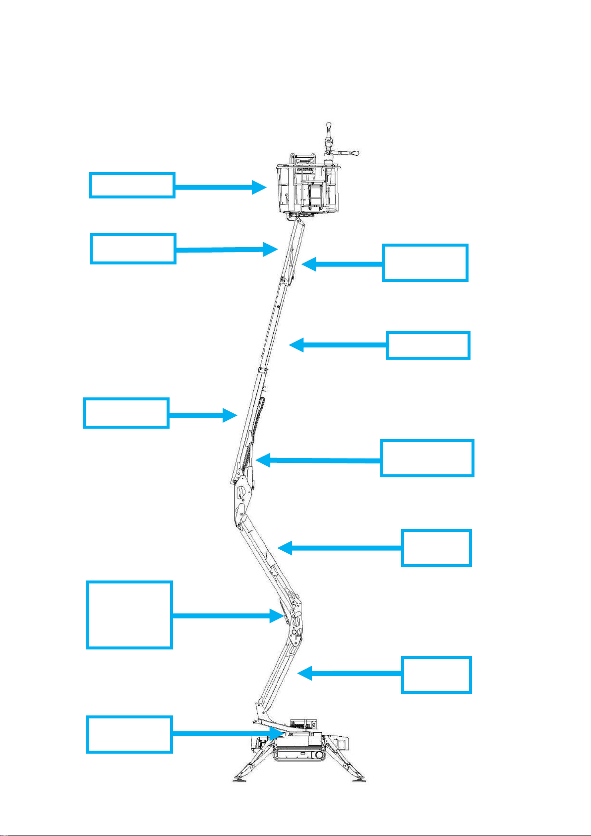
1.1 PARTS DENOMINATION
The base sides of the machine are established looking from inside the basket,
which is positioned in the rear side as indicated in the draft below.
The aerial part booms are numerated looking from the base, i.e. from the turret
slew ring, to the basket as indicated in the draft below.
All the machine movements are controlled by the machine remote control
supplied with the machine. Usually, the remote control is positioned in the
LEFT
SIDE
REAR
SIDE
FRONT
SIDE
RIGHT
SIDE
OUTRIGGER
N.1
OUTRIGGER
N.4
OUTRIGGER
N.3
OUTRIGGER
N.2
7
specific seat in the basket, anyway there are others options illustrated and
described later.
TELESCOPE
FIRST
BOOM
THIRD BOOM
CYLINDER
SECOND
BOOM
JIB
CYLINDER
BASKET
THIRD BOOM
FIRST AND
SECOND
BOOMS
CYLINDER
TURRET
SLEW RING
JIB
8
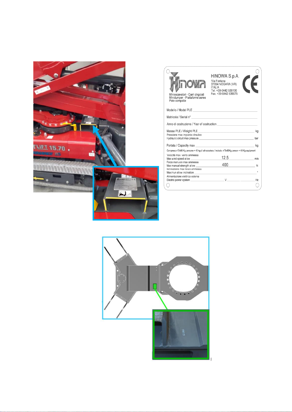
1.2 SERIAL NUMBER LOCATION
To identify the machine a serial number plate is affixed on to the frame of the
machine. The following illustrations showing its location.
The machine serial number is also printed on the frame.
SERIAL NUMBER PLATE
LOCATION

9
2. LL15.70 DATA
2.2 TECHINCAL SPECIFICATIONS
MACHINE ENGINE TECHNICAL
Platform capacity
230 Kg
Max height (basket floor level)
13,30 m
Max working height
15,40 m
Up & Over height
7,0 m
Max working horizontal extension
6,60 m
Basket dimensions (standard two persons basket)
1335x690xH1100mm
Length with basket installed
4020 mm
Length with basket off
3400 mm
Height
1990 mm
Undercarriage width (Retracted/Extended)
748 / 1100 mm
Stabilization area
2800x2800 mm
Rotation (non-continuous)
360°
Basket rotation
124° (+/- 62°)
Max reaction on the ground for outrigger
1670 daN
Max pressure on the ground for outrigger
2,36 daN/cm²
N° of operators
2
N° operators for optional one person basket
1
Jib function
89° (+0° / -89°)
Max aerial part working inclination
1°/ 1,75%
Max stabilization angle
15°
Gasoline machine operating weight (without operator)
1940 Kg
Diesel machine operating weight (without operator)
1960 Kg
Lithium machine operating weight (without operator)
1992 Kg
Gasoline/Diesel machine Max drive speed with double
speed
0,7/1,4/2,6 Km/h
Lithium machine Max drive speed with double speed
0,4/0,8/1,6 Km/h
Angle of attack
20° / 36%
Max admitted translation inclination in translation direction
(with tracks automatic speed control activated)
16° / 28,7%
Max admitted translation inclination in the translation
orthogonal direction (with tracks automatic speed control
activated)
13° / 23,1%
Max wind speed
12,5 m/s
Max manual force allowed
400 N
Hydraulic pressure of ground part (tracks-outriggers)
180 bar with engine
Hydraulic pressure aerial part
165 bar with engine
Hydraulic oil tank capacity
24 litres
Engine pumps capacity
double 2x3,15 cm³
Electric motor pumps capacity
double 2x3,15 cm³
Lithium electric motor pumps capacity
double 2x3,15 cm³
Electric system tension
12V

10
Battery
60Ah - 680A - 12V
Gasoline engine alternator current
10 A at 3600rpm
Diesel engine alternator current
14÷15 A at 3600rpm
Electric motor rated voltage
230V - 110V - 120V
Electric motor frequency
50Hz - 50Hz - 60Hz
Electric motor rated powers
2,2 Kw - 2,2 Kw - 1,2 Kw
DATA DIESEL ENGINE TECHNICAL
Brand/model
HATZ 1B40
Fuel/cooling
Diesel / Air
Power SAEJ1349
7,5 Kw (10HP) at
3600rpm
Max rated engine speed
3600 rpm
Max torque
25 Nm at 2000rpm
No. of cylinders
1
Displacement
462 cm³
Tank capacity
5 litres
GASOLINE ENGINE TECHNICAL DATA
Brand/model
HONDA iGX 390
Fuel/cooling
Gasoline / Air
Power SAEJ1349
8,7 kw (11,7HP) at
3600rpm
Max rated engine speed
3600 rpm
Max torque
26,4 Nm at 2500rpm
No. of cylinders
1
Displacement
389 cm³
Tank capacity
5,3 litres
LITHIUM PACK TECHNICAL DATA
Battery
100Ah
Electric motor rated voltage
36 V
Electric motor rated power
2 KW
On-board battery charger
220V±30V 50÷60 Hz
110V±30V 50÷60 Hz
11
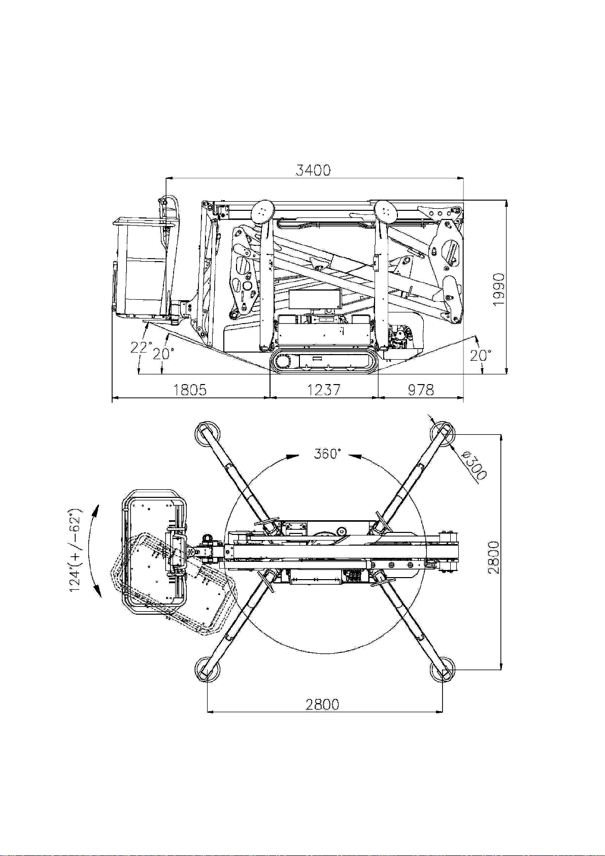
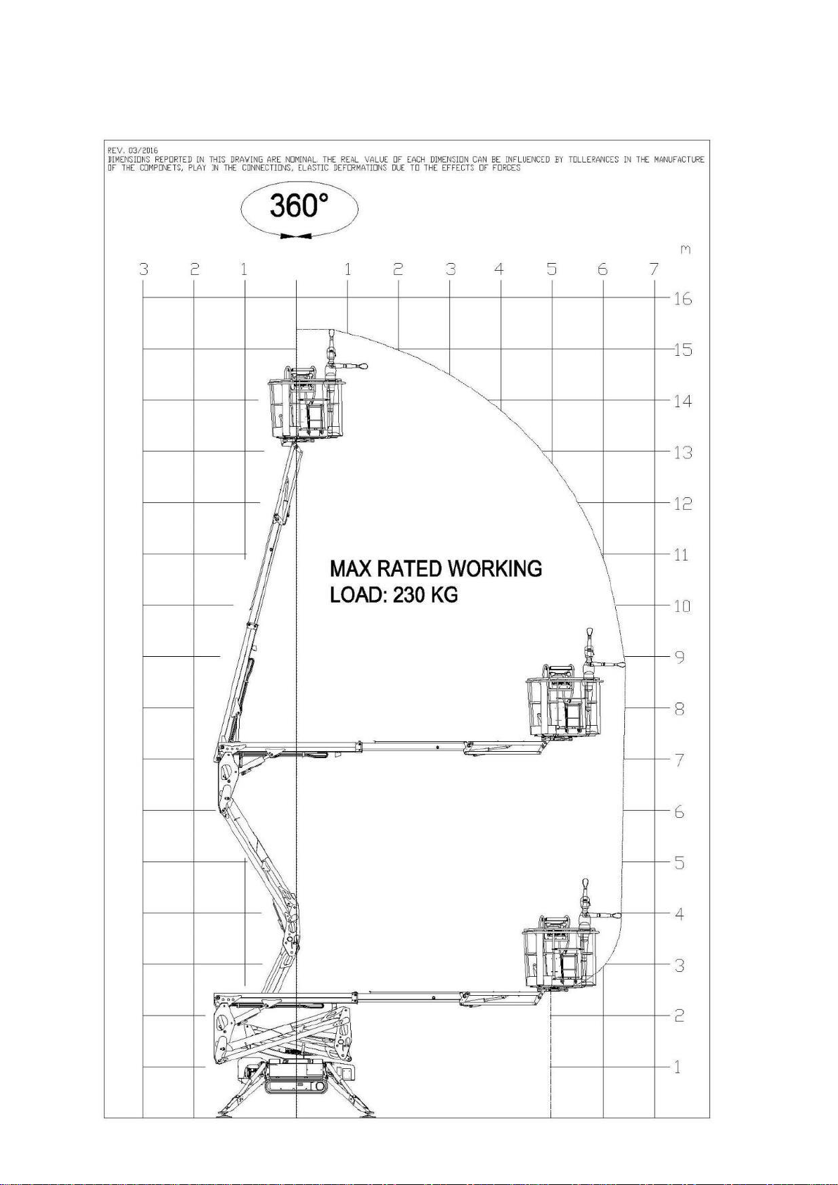
2.3 LL15.70 DIMENSIONS
MACHINE IS SHOWN HERE BELOW WITH THE 2 PERSONS BASKET,
DIMENSIONS REPORTED IN THIS DRAWING ARE NOMINAL, THE REAL VALUE
OF EACH DIMENSION CAN BE INFLUENCED BY COMPONETS MANUFACTURE
TOLLERANCES AND ELASTIC DEFORMATIONS DUE TO THE FORCES EFFECTS.

12
13
2.4 LL15.70 WORKING AREA - 230 KG UNRESTRICTED CAPACITY

14
3. MACHINE OPERATIONAL INTRODUCTION
The LL15.70 aerial platform is divided into two main parts:
Ground part (or undercarriage part)
Aerial part
Driving or using the outriggers we are using the ground part.
Moving the booms or the turret rotation we are using the aerial part.
All of those movements are carried out by the remote control.
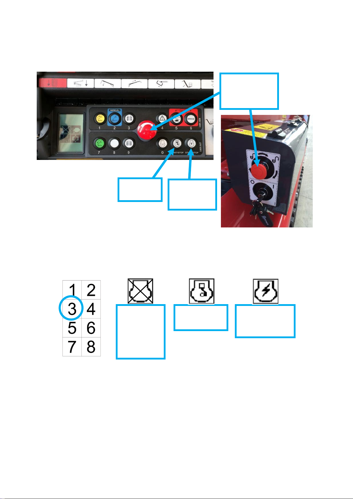
3.1 MACHINE IGNITION
To start up the machine the battery cutter must be active, when main key on
ground control box is turned ON display will show the following icon indicating
to press and release the remote control emergency stop button to initialize the
machine.
After stop button will be pressed and released the machine is ready to be used
and main display indications will be visualized.
INcas e ofnec
To switch ON the electric motor the machine need to be plugged to the local
electric network with a proper cable, shorter than 10m and with a minimum
section of 2,5mm2 (220V network) or 4mm2 (110V network).
To ignite engine or electric motor, both the emergency stop buttons, on the
remote control and on the ground control box, must be released.
MAIN KEY
TURNED
“ON”
BATTERY
CUTTER
INITIALIZATION
ICON
PRESS AND
RELEASE
THE STOP
BUTTON
15
Operator has to press the remote control “ENGINE”button to start it, or he
has to press the remote control “ELECTRIC MOTOR” button to switch it ON.
While engine or electric motor are running, the same relevant “ENGINE”or
“ELECTRIC MOTOR” buttons have to be used to switch them OFF. Also pressing
one emergency stop button engine or electric motor will be switched OFF.
Engine and electric motor cannot run together and the system avoids it, looking
at the display icon in position 3 it’s always possible to verify their condition.
To start the engine, on display position 3 has to be shown the first icon here
above.
After that machine has been used it must be switched OFF by the main key on
ground control box.
When outriggers are not touching the ground and both engine and electric
motor are switched OFF, but main key is still ON, remote control emits an
intermittent acoustic signal to remind the operator about to switch OFF the
main key.
NOTE: It’s not possible to start engine/electric motor while a joystick is pressed
ELECTRIC
MOTOR
RUNNING
ENGINE
REUNNING
NO
ENGINE/
ELECTRIC
MOTOR
RUNNING
ENGINE
BUTTON
EMERGENCY
STOP
BUTTONS
ELECTRIC
MOTOR
BUTTON

16
3.2 STOP BUTTONS
Machine is equipped with two emergency stop buttons, one on the remote
control that could be always use by the operator holding the remote control,
and another one outside the ground control box.
Pressing an emergency stop button the engine or the electric motor will be
switched OFF, avoiding any machine movement.
If the operator tries to start up the machine with one stop button pressed, the
"STOP PRESSED" icon will appear in the middle of the screen.
The emergency stops buttons work with dedicated 12 Volt lines not used by the
other machine sensors or devices.
In case of emergencies it’s possible to by-pass the remote control stop button
following the procedure indicated at APPENDIX 10.
3.3 REMOTE CONTROL FUNCTIONS
The remote control is essential for the machine: it displays all the information
on the platform status and any error message in case of incorrect use of the
controls. It is also possible to access the SERVICE menu, which indicates any
anomalies or malfunctioning of machine components.
The main icons on the display are disposed in 8 different positions, as illustrated
here above, other icons could be visualized in the middle of the screen.
“STOP PRESSED”
ICON

17
NOTE: The remote control joystick should not be kept pressed before to
initialize the machine, if one joystick is kept pressed before it will be deactivated
after initialization, in this case that’s enough to restart the machine to reset it.
NOTE: Lithium machine remote control has blank stickers on the position of
ENGINE PREHEATING, ENGINE (START-STOP) and ELECTRIC MOTOR (START-
STOP).
ENGINE
WARM UP
(ONLY FOR
GASOLINE
MACHINE)
OR
GRAVITY
EMERGENCY
DESCENT
LEFT TRACK
1-2 ARMS
JIB
TURRET
ROTATION
RIGHT TRACK
THIRD
BOOM
BASKET
ROTATION
TELESCOPE
ELECTRIC
MOTOR
(START-STOP)
ENGINE
(START-STOP)
UNDERCARRIAGE
CLOSING
AUTO-
STABILIZATION
ENGINE SPEED
SELECTOR
SINGLE
OUTRIGGER
MOVEMENT
SELECTOR
SERVICE
MENU
SELECTOR
DISPLAY
EMERGENCY
STOP
BUTTON
GROUND ASSENT
UNDERCARRIAGE
WIDENING
BASKET
LEVELING
KEY
OUTRIGGERS
AUTOMATIC
RETRACTION
18
4. GROUND PART MOVEMENTS
4.1 TRACKS MOVEMENTS
To allow tracks movements none of the outriggers have
to be touching the ground, doesn’t matter if completely
lifted up or just lifted, doesn’t matter if opened or in
stowed position.
When machine is not closed and aligned, if operator try to
move an outrigger display will remind that machine need
to be closed and aligned by the error message aside.
The operator has to act on the two external remote control red joysticks to
move the tracks.
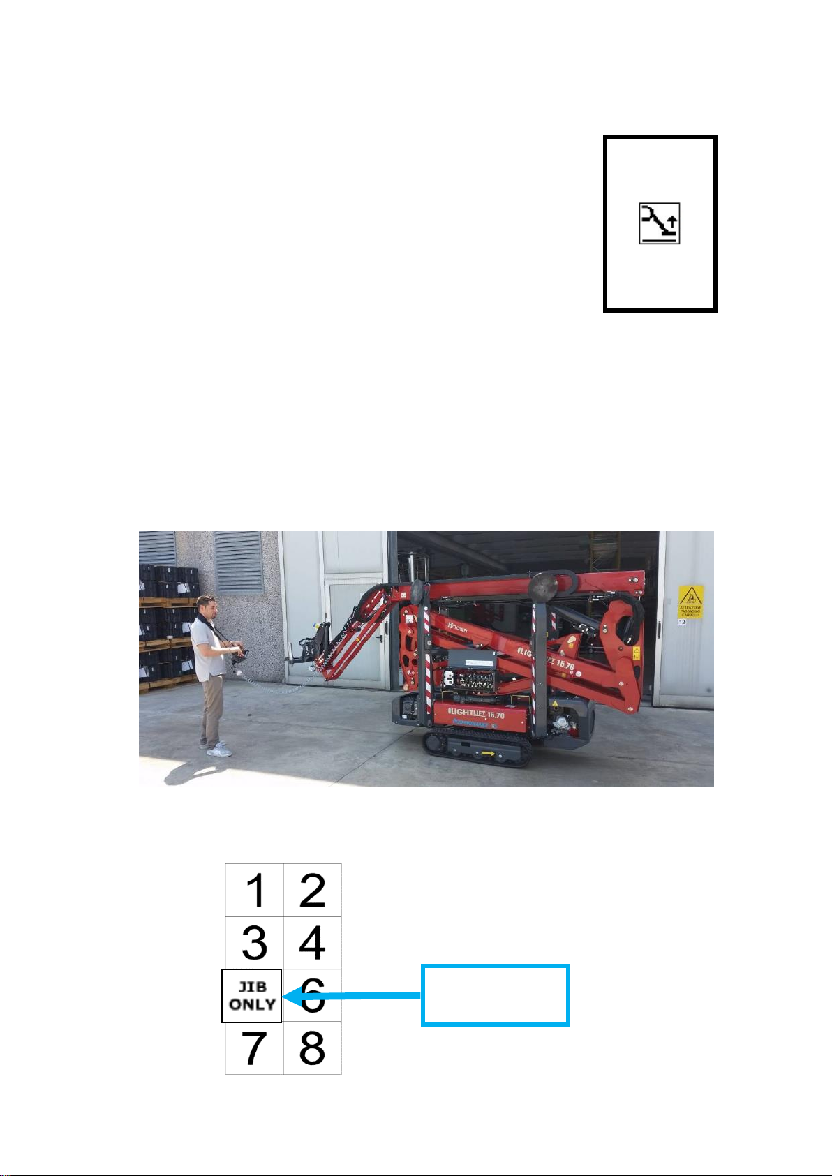
With the jib closed, it’s possible to drive the tracks standing on the ground or
standing on the basket.
To drive the tracks with jib opened the basket must be taken off its support
and operator will keep remote control in his hand.
NOTE: With Skyguard installed, to unload the basket it has to be
disconnected the Skyguard connector.
While none of the outriggers is touching the ground and basket is taken off its
support on the display is visualized the “JIB ONLY” icon.
“JIB ONLY”
ICON
ERROR
19
If in the basket is still on its support, it will be not possible to move the jib or
to drive the tracks with jib already opened.
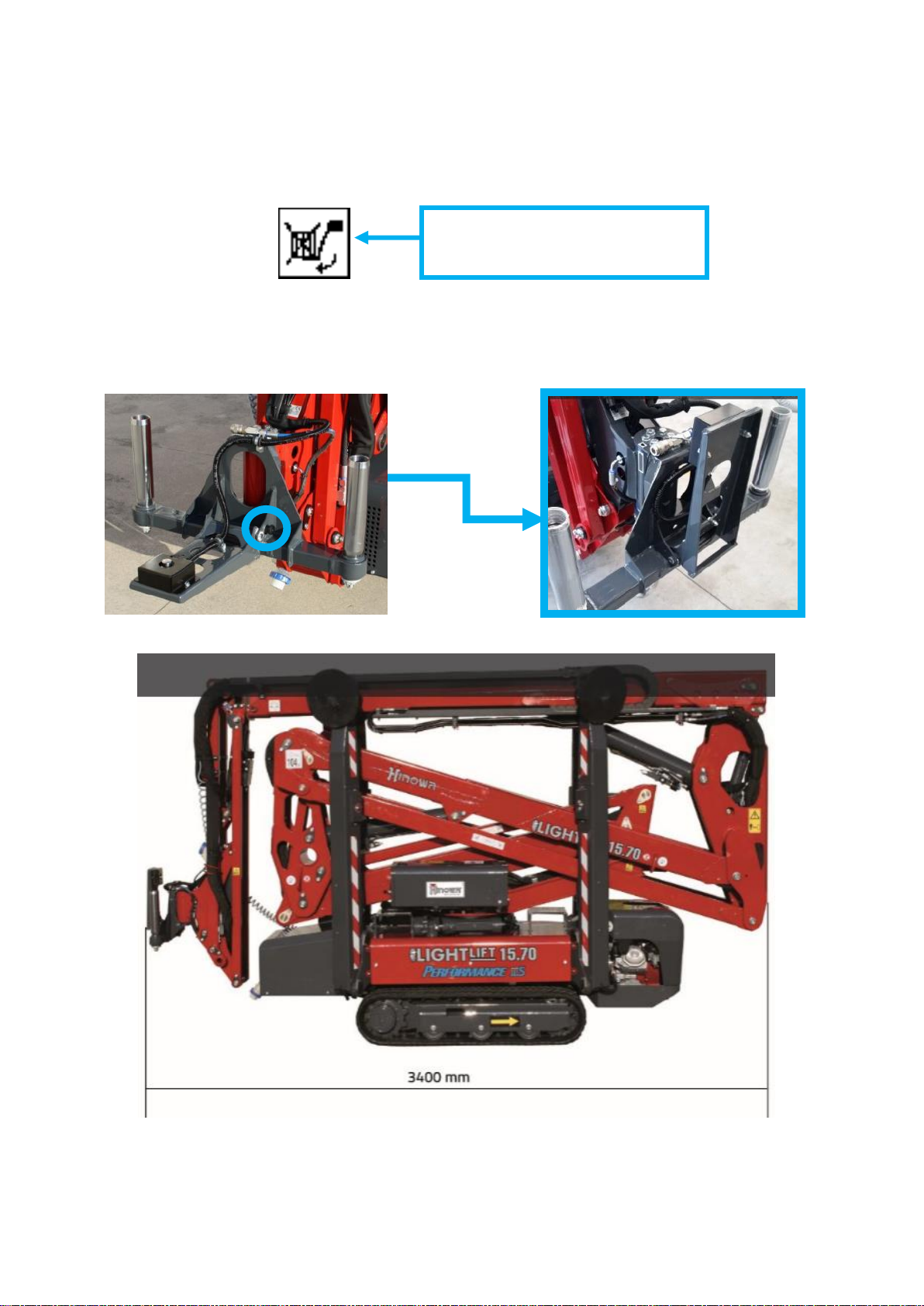
In those cases the error message “UNLOAD THE BASKET” will be displayed.
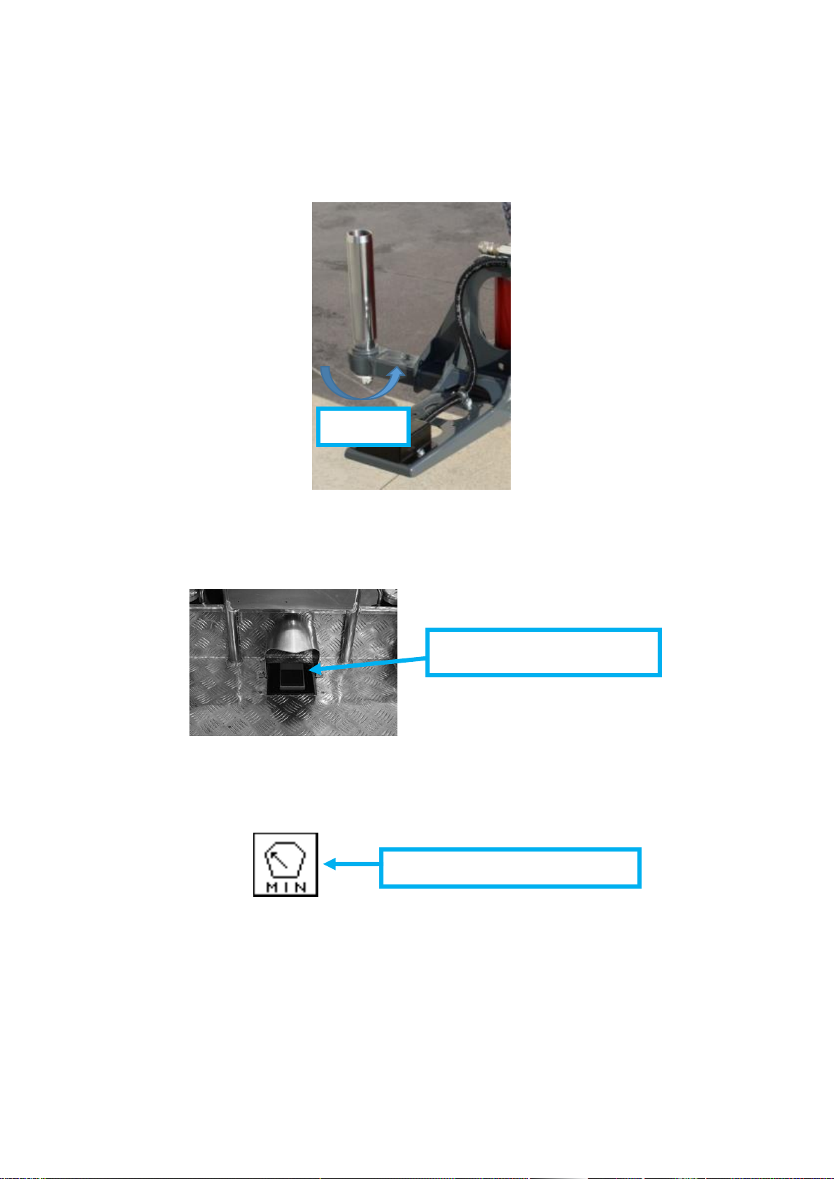
To reach the total length of 3400 mm the basket must be unloaded and its
support must be lifted acting on its pin, as indicated below.
“UNLOAD THE BASKET”
ICON
20
When basket is installed back on its support the two pins stoppers must be
completely screwed.
NOTE: In case of need, basket pin must be screwed at 50Nm.
If pedal option is active and the remote control is on its basket support the
operator standing into the basket has to press the pedal while moving the
tracks.
For safety reason, as soon as the basket is lifted from the load cell sensor, the
aerial part movements are disabled and display shows “LOAD MIN”icon.
NOTE: If pedal option is active and the remote control is on its basket support
the operator standing into the basket has to press the pedal while moving the
tracks.
“LOAD MIN” ICON
50Nm
PEDAL IN THE BASKET
Table of contents
Other Hinowa Lifting System manuals


Popular Lifting System manuals by other brands


Atlas
Atlas BP8000 How to Do

Opera
Opera Signature Dual Link Kit Installation guide and technical specifications

Wilo
Wilo DrainLift XXL Series Installation and operating instructions

Snorkel
Snorkel S3010E Parts & service manual

Grundfos
Grundfos Multilift MD1 Installation and operating instructions

LGMG
LGMG SR1018D Operation manual