Hinowa GOLDLIFT 14.70 Instruction manual

MUGL147020409
MANUAL USE AND MAINTENANCE
SELF
SELF-PR
-PROPELLED TRA
OPELLED TRAC
CKED PL
KED PL A
ATF
TFORM
ORM
GOLDLIFT
GOLDLIFT 1
14.70
4.70
Valid from serial number G23

SELF-PROPELLED TRACKED PLATFORM GOLDLIFT 14.70
HINOWA
INDEX
CHAPTER 1 FOREWORD........................................................................................................Page 05
CHAPTER 2 OPERATOR’S MANUAL .................................................................................Page 05
2.1 DESCRIPTION OF THE MACHINE ................................................................Page 05
2.1.1 MACHINE IDENTIFICATION PLATE............................................................Page 06
2.1.2 OVERALL DIMENSIONS OF THE MACHINE .............................................Page 07
2.1.2.1 GOLDLIFT 14.70 DIMENSIONS.......................................................................Page 07
2.1.3 TECHNICAL DATA............................................................................................Page 08
2.1.3.1 PLATFORM TECHNICAL DATA.....................................................................Page 08
2.1.3.2 PETROL ENGINE TECHNICAL DATA ..........................................................Page 09
2.1.3.3 DIESEL ENGINE TECHNICAL DATA ............................................................Page 09
2.1.3.4 HYDRAULIC SYSTEM TECHNICAL DATA..................................................Page 09
2.1.3.5 ELECTRIC SYSTEM TECHNICAL DATA.......................................................Page 10
2.1.4 TERMINOLOGY..................................................................................................Page 10
2.1.4.1 GOLD LIFT 14.70 KEY........................................................................................Page 11
2.2 GENERAL SAFETY RULES ...............................................................................Page 12
2.3 SAFETY ADVICE ................................................................................................Page 14
2.3.1 GENERAL ADVICE ............................................................................................Page 14
2.3.2 PICTOGRAMS SITUATED ON THE MACHINE ..........................................Page 14
2.3.3 NOISE AND VIBRATIONS................................................................................Page 23
2.4 INSTRUMENTS AND CONTROLS .................................................................Page 23
2.4.1 BASKET CONTROL DEVICE............................................................................Page 23
2.4.1.1 BASKET ELECTRIC PANEL..............................................................................Page 23
2.4.1.2 BASKET HYDRAULIC CONTROLS FOR MODEL 14.70 .................................Page 26
2.4.1.4 CRAWLER HYDRAULIC CONTROLS ..............................................................Page 28
2.4.1.5 GROUND EMERGENCY CONTROLS SITUATED ON THE REVOLVING TURRET .....Page 31
2.5 SAFETY DEVICES...............................................................................................Page 33
2.5.1 BATTERY CUTOUT ............................................................................................Page 34
2.5.2 DISTRIBUTOR OVERPRESSURE VALVES .....................................................Page 34
2.5.3 CYLINDER STOP VALVES ................................................................................Page 35
2.5.4 PHOTOELECTRIC CELL AND SWITCH ALIGNMENT OVERHEAD
PART OF THE FRAME AND MACHINE BASE ...........................................Page 35
2.5.5 ENABLING DEVICE OF THE FRAME OVERHEAD PART ........................Page 36
2.5.6 SENSOR OF CONTROL CAR LOAD...............................................................Page 36
2.5.7 CONTROL GUARDS..........................................................................................Page 37
2.5.8 THE WATER LEVEL ..........................................................................................Page 37
2.5.9 LOCKING PIN SCREWS AND NUTS .............................................................Page 38
2.6 EMERGENCY DEVICES ....................................................................................Page 38
2.6.1 EMERGENCY STOP PUSHBUTTON...............................................................Page 39
2.6.2 SWITCH ENABLING EMERGENCY CONTROLS.......................................Page 39
2.6.3 HAND PUMP ......................................................................................................Page 40
2.6.4 SOLENOID VALVES FOR EMERGENCY DESCENT....................................Page 41
2.7 SAFETY REGULATIONS TO OBSERVE BEFORE USING THE PLATFORM ......Page 42
2.7.1 DANGER OF ELECTRIC FULMINATION .....................................................Page 42
2.7.2 DANGER DUE TO BAD WEATHER CONDITIONS ....................................Page 43
2.7.3 DANGER DUE TO THE WORKING AREA ...................................................Page 43
2.8 PROCEDURES FOR A PROPER USE...............................................................Page 44
2.8.1 OPERATOR’S RECAPITULATORY TABLE OF SAFETY REGULATIONS .....Page 44
2.8.2 GOLD LIFT 14.70 WORKING AREA ...............................................................Page 45
2.9 USE OF THE OVERHEAD PLATFORM..........................................................Page 46
2.9.1 PRELIMINARY CHECKS BEFORE STARTING OPERATING ....................Page 47
2.9.2 START OF THE PETROL/DIESEL (OPTIONAL) ENGINE ..........................Page 48
2.9.3 START OF THE ELECTRIC ENGINE ..............................................................Page 49
2.9.4 TRANSLATION...................................................................................................Page 49
2.9.4.1 PARKING OF THE MACHINE ON A SOLPE OR DISCONNECTED GROUND....Page 51
2.9.5 STABILISING AND LEVELLING THE MACHINE.......................................Page 51
2.9.6 MOVING THE CONTROL CAR.......................................................................Page 52
2.9.7 MANUAL LEVELLING OF THE CONTROL CAR .......................................Page 54
2.9.8 MANOEUVRING THE BASKET EMERGENCY DESCENT........................Page 55
2.9.8.1 ACTIVATING THE BASKET EMERGENCY DESCENT...............................Page 55
2.9.8.2 ACTIVATING THE GROUND EMERGENCY DESCENT WITH
THE MACHINE IN PERFECT WORKING ORDER......................................Page 56
1

2.9.8.3 ACTIVATING THE GROUND EMERGENCY DESCENT WITH THE
HAND PUMP IN CASE OF ALL THE ENERGY SYSTEMS BREAKDOWN ....Page 56
2.9.9 MAIN USES PLANNED FOR THE PLATFORM ...........................................Page 58
2.9.9.1 SYSTEMS ..............................................................................................................Page 58
2.9.9.2 CLOSED PREMISES............................................................................................Page 58
2.9.9.3 USING FOR PRUNING......................................................................................Page 58
2.9.9.4 USE FOR REPAIRS AND MAINTENANCE OF ROOFS AND RAIN PIPES......Page 58
2.9.9.5 USE FOR PAINTING, SAND BLASTING AND PLASTERING...................Page 59
2.9.9.6 USE IN SALTY ENVIRONMENT....................................................................Page 59
2.10 REMOVAL OF THE BASKET............................................................................Page 59
2.11 TRANSPORT SAFETY REGULATIONS..........................................................Page 60
2.11.1 LOADING AND UNLOADING ON RAMPS.................................................Page 60
2.11.2 LIFTING THE MACHINE .................................................................................Page 61
2.11.2.1 HOW AND WHERE TO HOOK THE PLATFORM.......................................Page 62
2.11.2.2 WHAT TO USE FOR HOOKING THE PLATFORM......................................Page 62
2.11.3 TRANSPORT OF THE MACHINE...................................................................Page 63
CHAPTER 3 SPECIFICATIONS FOR GREASING AND LUBRICATING ...................Page 63
3.1 SAFETY RULES FOR GREASING AND LUBRICATING .............................Page 63
3.2 LUBRICATING POINTS ....................................................................................Page 64
3.3 GREASING POINTS ..........................................................................................Page 64
3.3.1 GREASING THE TELESCOPIC ARM..............................................................Page 65
CHAPTER 4 MAINTENANCE OF THE MACHINE ..........................................................Page 65
4.1 SAFETY REGULATIONS FOR MAINTENANCE OPERATIONS...............Page 65
4.2 PERIODIC GENERAL CONTROL ...................................................................Page 66
4.2.1 PERIODICAL MAINTENANCE TIMES..........................................................Page 67
4.3 RUBBER TRACK MAINTENANCE.................................................................Page 69
4.3.1 CHECKING TRACK TENSION........................................................................Page 69
4.3.2 OPERATIONS TO LOOSEN OR TIGHTEN TRACK.....................................Page 69
4.3.3 CHECKING RUBBER TRACKS ........................................................................Page 70
4.3.4 REPLACING RUBBER TRACKS.......................................................................Page 72
4.4 CHECKING BOLTS AND NUTS TIGHTNESS...............................................Page 74
4.5 CHECKING HYDRAULIC OIL LEVEL...........................................................Page 75
4.6 CHECKING LEAKS FROM THE HYDRAULIC SYSTEM............................Page 75
4.7 CHECKING FILTER CARTRIDGE...................................................................Page 75
4.8 CHECKING THE MACHINE PLATES INTEGRITY ...................................Page 76
4.9 CHECKING WORKING PRESSURES OF THE HYDRAULIC SYSTEM....Page 76
4.10 CHECKING THE TIGHTENING OF THE FIXING SCREWS OF
THE PIN STOPS AND THE RING NUTS ...........................................................Page 77
4.11 CHECKING WEAR AND TEAR OF THE TELESCOPIC ARM
SLIDING BLOCKS ..............................................................................................Page 77
4.12 CONTROL OF WEAR AND TEAR OF THE INTERIOR SLIDING RING EXTENSION.Page 77
4.13 BATTERY: CHECKS AND MAINTENANCE.................................................Page 78
4.13.1 CHECKING ELECTROLYTE.............................................................................Page 78
4.13.2 RECHARCHING THE BATTERY.....................................................................Page 78
4.13.3 REPLACING THE BATTERY ............................................................................Page 79
4.13.4 DISCARDING THE BATTERY..........................................................................Page 79
4.14 ENGINE MAINTENANCE................................................................................Page 79
CHAPTER 5 TROUBLESHOOTING .....................................................................................Page 80
CHAPTER 6 CHECKING THE MACHINE AFTER REPAIRS .........................................Page 81
6.1 CHECKING THE PROPER WORKING OF THE CONTROLS....................Page 81
6.2 CHECKING THE PROPER WORKING OF THE SAFETY DEVICES.........Page 81
CHAPTER 7 HYDRAULIC SYSTEM .....................................................................................Page 82
7.1 GOLDLIFT 14.70 HYDRAULIC SYSTEM........................................................Page 82
7.2 KEY DIAGRAM GOLDLIFT 14.70 HYDRAULIC SYSTEM..........................Page 83
7.3 GOLDLIFT 14.70 HYDRAULIC SYSTEM WITH 2ND SPEED........................Page 84
7.4 KEY DIAGRAM GOLDLIFT 14.70 HYDRAULIC SYSTEM WITH 2ND SPEED .....Page 85
CHAPTER 8 ELECTRIC SYSTEM ..........................................................................................Page 86
2

3
FOREWORD
The aim of this manual is to provide the customer with all the necessary instructions and
operating procedures essential for the proper use of the machine in order to avoid serious
damages to the machine or others.
IMPORTANT
ALL THE INFORMATION IN THIS MANUAL IS MANDATORY AND MUST BE READ
CAREFULLY AND UNDERSTOOD BEFORE STARTING ANY OPERATION ON THE
MACHINE.
Being an important working tool, this manual must always be kept in a safe and easy to
reach place to be available at any time for further explanations.
Since it is not possible for the manufacturer to check the application of the machine and its
operation.
THE OPERATOR IS RESPONSIBLE to observe the safety instructions described in this
manual.
Before delivery, each machine is checked and tested carefully so that the operator does not
need to do any further adjustments.
IT IS ABSOLUTELY FORBIDDEN AND THE RESPONSIBILITY IS AT THE OPERATOR’S
OWN RISK to do any alterations and/or adjustments without any prior authorisation from
HINOWA SPA.
IT IS THE EMPLOYER’S RESPONSIBILITY TO MAKE SURE THE OPERATOR HAS THE
NECESSARY SKILLS AND ABILITIES TO OPERATE PROPERLY THE MACHINE AND
THAT HE HAS READ AND UNDERSTOOD THE CONTENTS OF THIS INSTRUCTION
AND OPERATING MANUAL.
IT IS ALSO THE EMPLOYER’S RESPONSIBILITY TO TRAIN THE OPERATOR ACCOR-
DING TO NATIONAL LAWS WHICH MIGHT BE SUPPLEMENTARY TO THE CONTENTS
OF THIS MANUAL.
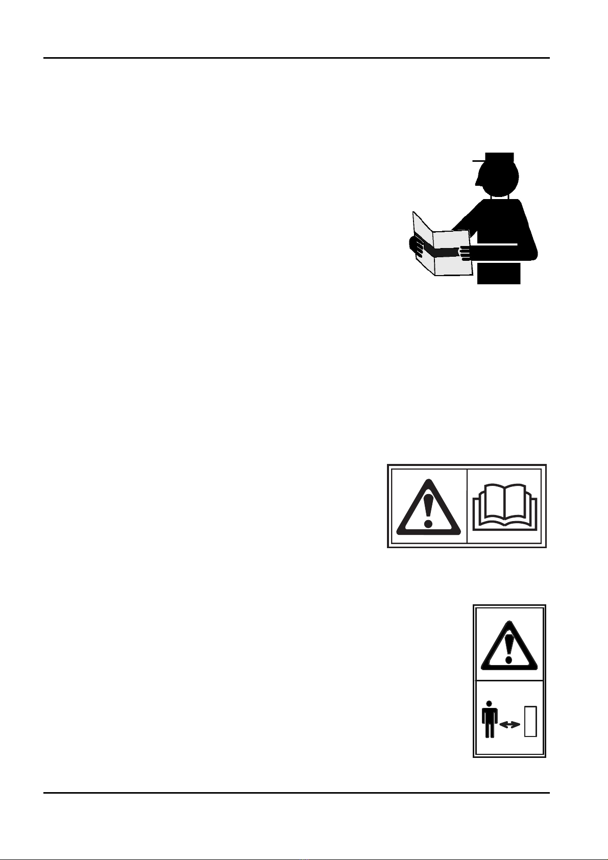
If this manual gets damaged or lost, ask directly HINOWA SPA for a replacement copy.
Note: all the pictures and drawings in the manual have been added to simplify the com-
prehension of the texts. The machine in your possession may differ from the pictures and the
drawings in some details.
SELF-PROPELLED TRACKED PLATFORM GOLDLIFT 14.70
HINOWA

APPLIED STANDARDS
This machine has been planned, built and tested according to the prescribed harmonised
regulations EN280 which supplies the presumption of conformity to the Essential Safety
requirements of the Machine Directive 98/37/CE although it is a type C Voluntary Technical
Rule. According to what prescribed in EN280 the platform GOLDLIFT has been classified in
GROUP B, as the vertical projection of the load centre of gravity always remains outside the
overturn lines and in TYPE I as the translation is only allowed when the platform is at rest.
CUSTOMER SERVICE
In case of repairs or overhauls of the following parts of the machine:
- Locking valves;
- Sensors (microswitches, photoelectric cells, loading sensors etc.);
- Main part of the electric system (PLC).
IT IS OBLIGATORY to contact the dealer where the platform has been purchased or directly
HINOWA SPA Customer Service. They have highly qualified staff and above all the suitable
equipment to carry out the necessary operations in complete safety.
When doing ordinary maintenance or repairs, ONLY USE ORIGINAL SPARE PARTS pur-
chased from the dealer where the platform has been bought or directly from HINOWA Spa
Spare parts Department.
WARRANTY
When purchasing a platform GOLDLIFT you are given a warranty and test certificate where
the warranty terms are clearly stated and where there must be specified any interventions on
the machine.
LIABILITY
HINOWA SPA declines any responsibility or obligations for any damages caused to people
or things due to the following reasons:
• Not observing the instructions indicated in this INSTRUCTION AND OPERATING
MANUAL with regard to the operating, use and maintenance of the machine;
• Any sudden or violent actions or wrong manoeuvres in the use and maintenance of the
machine;
• Any alterations done to the structure and the components of the machine without any
prior authorisation from HINOWA SpA and/or without using proper equipment;
• Any foreign events not related to the ordinary and proper use of the machine as descri-
bed in this INSTRUCTION AND OPERATING MANUAL;
• Using non original and non authorised manufactured spare parts.
SELF-PROPELLED TRACKED PLATFORM GOLDLIFT 14.70
HINOWA
4

5
1. INTRODUCTION
In this manual, you can see safety-warning signs used to bring the reader’s attention to some
warnings of particular importance.
The warning signs comes under two main types identified and described below.
DANGER
This sign accompanied by the word DANGER indicates that the situation descri-
bed below, if not avoided, can cause serious injuries or even death to the people
concerned (operator, ground staff, people near the platform, people assigned to
maintenance etc.).
WARNING
This sign accompanied with the word WARNING indicates that the situation
described below indicates a potential risk to the structure of the machine. This
condition could cause dangerous conditions (even injuries and death) to the peo-
ple concerned.
2. OPERATOR’S MANUAL
2.1. DESCRIPTION OF THE MACHINE
The GOLD LIFT machine is a self-propelled hydraulic lifting device, equipped with a
working control car situated at the top of a rotating and extensible articulated structure. The
lifting device GOLD LIFT is meant for PLACING PEOPLE AND THEIR TOOLS AND
MATERIALS IN PLACES HIGHER THAN GROUND LEVEL.
The main control station of all the movements of the lifting device GOLD LIFT is situated on
the control car. Thanks to the main control station the operator can drive the machine, lift or
lower the extensible structure and rotate it towards the left or the right for an overall 300°
angle.
The machine GOLD LIFT is equipped with a ground control station that excludes the main
control station by means of a switch. The ground controls check the movements of the exten-
sible structure and are used in case of emergency to bring the control car back to the ground
when the operator is not able to do it.
The ground emergency controls can be used when doing control checks before starting ope-
rating.
The machine GOLD LIFT is a self-propelled machine able to move easily on any type of
ground, able to overcome big slopes and, seen its contained dimensions, to enter into narrow
places. The control car is the only control location planned by the manufacturer that prevents
the operator from being injured during all the translation operations of the machine. In fact,
the controls have been studied to be used from the said position to have a proper sight of the
involved area.
The travel function can be controlled from the ground position only when the machine has to
pass pass through reduced-height or narrow spaces. In these cases, to allow the machine to
access these spaces, the two-place cage must be removed. The machine must travel only
lengthwise and must be controlled by a specialist operator.
SELF-PROPELLED TRACKED PLATFORM GOLDLIFT 14.70
HINOWA

When controlling the translation of the machine from the control car, take the maximum care
of elements like cornices, terraces, lintels, branches etc. that could come into contact with the
operator.
If the machine translation is controlled from the ground (see the a.m. admitted cases),
remember that the machine must be orientated with the control car part towards the back so
that, in case of a wrong manoeuvre, the operator does not come into contact with the rubber
tracks.
Controlling the travel of the machine from the ground with the cage removed is conside-
red an extraordinary procedure that should be adopted only when the work area cannot be
reached in any other way.
It is absolutely forbidden to do manoeuvres different from the above mentioned ones by con-
trolling translation from the ground as a possible sharp movement of the machine could
crush the operator between itself and the elements present on the manoeuvring area or make
the operator come into contact with the rubber tracks or the platform stabilisers.
After reinstalling the cage, put back the iron caps immediately.
2.1.1 MACHINE IDENTIFICATION PLATE
The Manufacturer plate is situated on the right
side of the metallic frame sustaining the transla-
tion/stabilising controls. You can see the drawing
below.
SELF-PROPELLED TRACKED PLATFORM GOLDLIFT 14.70
HINOWA
6
7
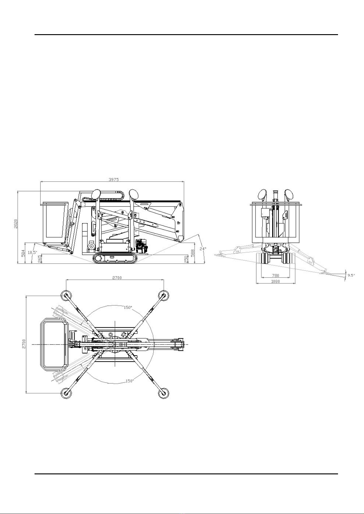
2.1.2 OVERALL DIMENSIONS OF THE MACHINE
2.1.2.1 DIMENSIONS 1470
Maximum length in running conditions........................3975 mm
Carriage width ..................................................................780-1080 mm
Maximum height in running conditions........................1980 mm
Maximum ramp angle ......................................................18.5°
Maximum stabilising angle..............................................10°
Stabiliser base side ............................................................2700 mm
N.B. Standard version with two-seater basket.
SELF-PROPELLED TRACKED PLATFORM GOLDLIFT 14.70
HINOWA

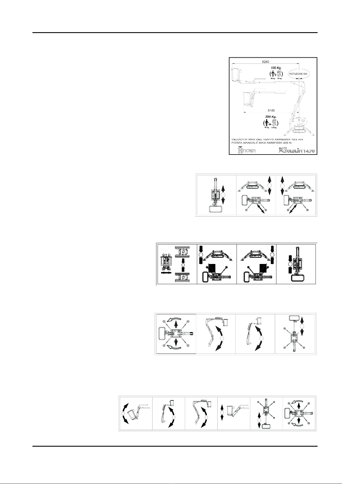
2.1.3 TECHNICAL DATA
2.1.3.1 PLATFORM TECHNICAL DATA
GOLDLIFT 14.70
....................................................................................................LOAD 200 kg ....LOAD 120 kg
PLATFORM HEIGHT (tread level ) ......................................10,58 m ..........11,94 m
MAXIMUM WORKING HEIGHT ............................................12,63 m ..........14,00 m
STANDARD CONTROL CAR DIMENSIONS ..............................1330x694 H1100 mm
HORIZONTAL RANGE ..........................................................5,16 m ............6,24 m
MAXIMUM WORKING HORIZONTAL RANGE ..........................5,61 m ............7,00 m
ROTATION (non continuous) ....................................................300°................300°
PLATFORM CAPACITY ..........................................................200 kg, ............120 kg
MAX GROUND REACTION PER STABILISER ..............................................1330 daN
MAX GROUND PRESSURE PER STABILISER ..........................................1,9 daN/cm2
OPERATORS N° ............................................................................2 ....................1
OPERATOR N° IN SINGLE- SEATER BASKET (OPTION) ..................1 ....................1
JIB-TYPE ARTICULATION ............................................................../ ......80° (+0°/-80°)
MAX WORKING INCLINATION....................................................................1°/2,2%
MAX STABILISING INCLINATION......................................................................10°
OVERALL WEIGHT IN TRANSPORT POSITION..............................................1700 kg
THERMIC ENGINE....................................................HONDA GX270-9 CV-3000 rpm
............................................................HONDA GX390-13 CV-3000 rpm (Optional)
....................................................................................HATZ 1B30-7 CV-3000 rpm
ELECTRIC ENGINE......................................................1,5 kw/220V/50Hz 1500 rpm
..................................................................1,5 kw/110V/50Hz 1500 rpm (Optional)
TELECTRIC SYSTEM VOLTAGE..........................................................................12 V
PUMPS ....................................................................................................2x3,15 cc
MAX TRANSLATION SPEED (thermic engine) ............................................1,4 km/h
MAX TRANSLATION SPEED (thermic engine) with 2nd speed (optional) ........1,4/2,8 km/h
STAB/TRANSLATION SYSTEM PRESSURE ....................................................175 bar
OVERHEAD PART PRESSURE ......................................................................180 bar
MAX UPPER SLANT IN RUNNING CONDITIONS..........................................24°/53%
MAX WIND SPEED....................................................................................12,5 m/s
MAX ADMITTED MANUAL FORCE ..................................................................40 kg
RUBBER CRAWLER WIDTH- OPEN/CLOSE ........................................780/1080 mm
NB: The side range is measured from the centre of the fifth wheel to the outer
side of the control car.
SELF-PROPELLED TRACKED PLATFORM GOLDLIFT 14.70
HINOWA
8

9
It is absolutely forbidden to translate and/or manoeuvre on transversal slopes with the craw-
ler not extended as the machine could turn over and cause serious damages to the operator.
2.1.3.2 PETROL ENGINE TECHNICAL DATA
Make/ModelHONDA GX270
Fuel/coolant ........................................................................PETROL/AIR
Power SAEJ1349 ................................................................6.6 kW (9 CV) / 3600 Giri/min
Max regulated rpm............................................................3000 giri/min
Maximum torque ..............................................................19.1 Nm/2500 Giri/min (80/1269/EC)
Cylinder n° ..........................................................................1
Cubic capacity....................................................................270 cm3
Make/Model ......................................................................HONDA GX390
Fuel/coolant ........................................................................PETROL/AIR
Power SAEJ1349 ................................................................9.6 kW (13 CV) / 3600 Giri/min
Max regulated rpm............................................................3000 giri/min
Maximum torque ..............................................................26.5 Nm/2500 Giri/min (80/1269/EC)
Cylinder n° ..................................................................................1
Cubic capacity....................................................................389 cm3
2.1.3.3 DIESEL ENGINE TECHNICAL DATA
Make/Model ......................................................................HATZ 1B30
Fuel/coolant ........................................................................DIESEL/AIR
Power SAEJ1349 ................................................................5,0 kW (6,8 CV) / 3600 Giri/min
Max regulated rpm............................................................3000 giri/min
Maximum torque ..............................................................18,2 Nm/2000 Giri/min (80/1269/EC)
Cylinder n° ........................................................................1
Cubic capacity....................................................................347 cm3
2.1.3.4 HYDRAULIC SYSTEM TECHNICAL DATA
Hydraulic oil tank capacity..............................................25 litres
Pump ..................................................................................double 2x3.15cm3
Hydraulic system max pressure......................................180 bar
For further information please consult the hydraulic diagram annexed to this manual or the
paragraph relative to the maintenance of the relative components.
SELF-PROPELLED TRACKED PLATFORM GOLDLIFT 14.70
HINOWA
DANGER
2.1.3.5 ELECTRIC SYSTEM TECHNICAL DATA
Battery ................................................................................35 Ah - 125 A - 12V
Alternator: - petrol engine..............................................10 A (3000rpm)
- diesel engine ..............................................14 A (3000rpm)
Electric engine: - electrical connection..........................220 V
- frequency............................................50 Hz
- power ..................................................1.5 kW
For further information please consult the electric diagram annexed to this manual or the
paragraph relative to the maintenance of the relative components.
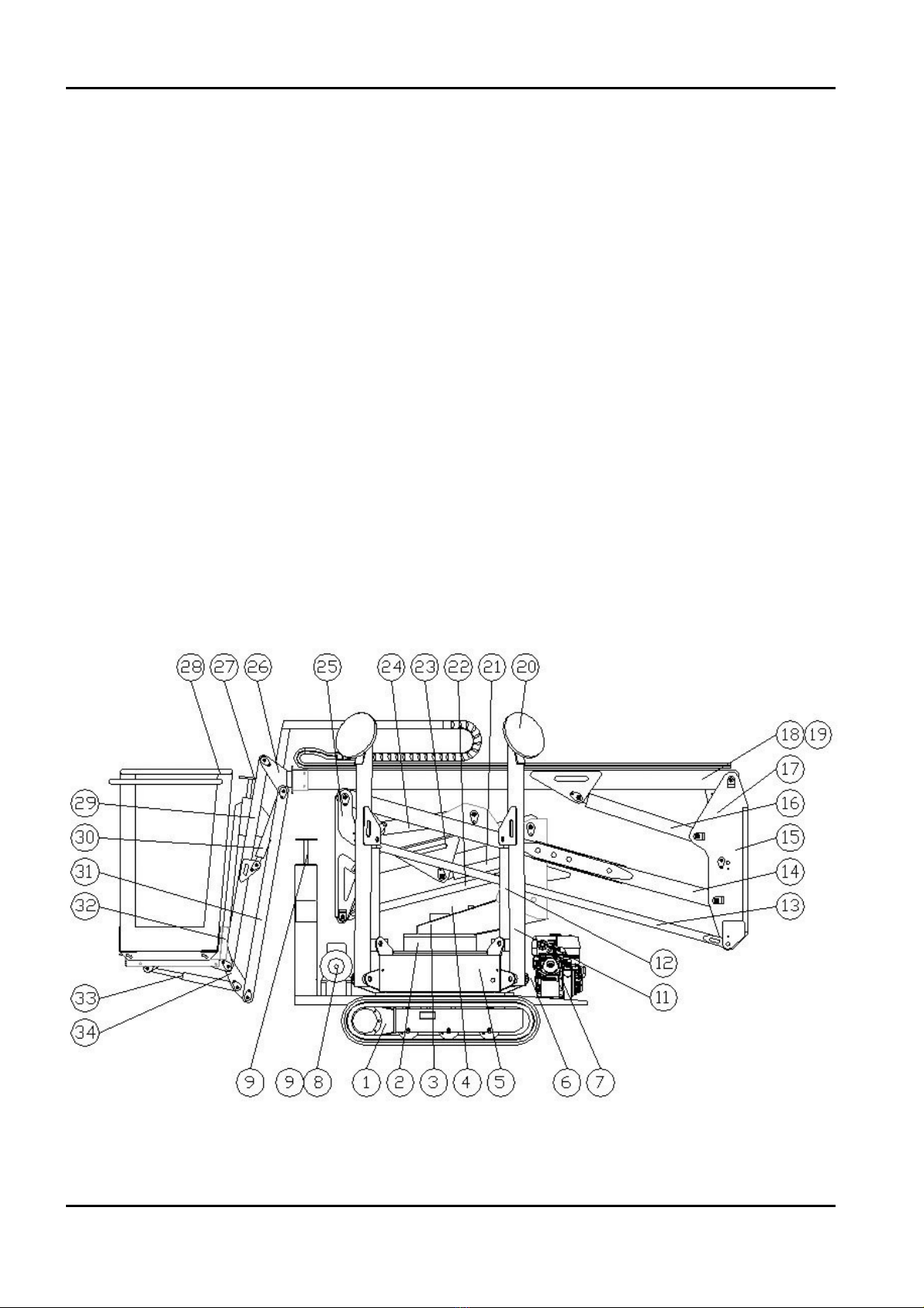
2.1.4 TERMINOLOGY
To make this manual easier to understand, there is a diagram that gives all the exact terms
identifying the different parts of the platform.
GOLD LIFT 14.70
SELF-PROPELLED TRACKED PLATFORM GOLDLIFT 14.70
HINOWA
10

11
2.1.4.1 GOLD LIFT 14.70 KEY
1Extensible rubber crawler
2Fifth wheel + rotation engine
3Revolving turret
4Overhead part emergency controls
5Base + electric components box + oil tank
6Triple gear pump
7Diesel/petrol engine
8Electric engine
9Triple gear pump
10 Translation and stabilisers controls
11 Stabilizer
12 Stabilizer cylinder
13 Second arm tie-rod
14 Second arm
15 Second transmission
16 Third arm cylinder
17 Basket levelling cylinder on transmission
18 Third arm
19 Extraction cylinder
20 Stabilizer cap
21 First arm cylinder
22 First arm tie- rod
23 First arm
24 Second arm cylinder
25 First transmission
26 Extraction arm
27 Controls
28 Basket or control car
29 Jib arm
30 Jib cylinder
31 Jib tie-rods
32 Basket support
33 Basket levelling cylinder on jib
34 Jib transmission
SELF-PROPELLED TRACKED PLATFORM GOLDLIFT 14.70
HINOWA
2.2 GENERAL SAFETY RULES
NOT OBSERVING THE SAFETY PRECAUTIONS LISTED IN THIS SECTION AND
SHOWN ON THE MACHINE CAN CAUSE INJURIES OR DEATH TO THE STAFF AND
DAMAGES TO THE MACHINE AND IS A SERIOUS VIOLATION OF SAFETY RULES.
This section of this INSTRUCTION AND OPERATING MANUAL describes the dangerous
procedures or situations that could cause damages to things and/or people and what the
operator must do to avoid them.
• The operator must always work professionally, observing all the safety rules, taking care
not to underestimate their own responsibility towards themselves and all the things and
people around them.
• Before starting work it is essential that the operator makes sure the safety devices are in
perfect conditions, that they make the necessary checks on the machine and become fami-
liar with the ground conditions where they must manoeuvre and stabilise.
• When working it is essential that one specialised person with knowledge of the use of the
machine and the contents of this INSTRUCTION AND OPERATING MANUAL stays on
the ground.
• It is absolutely forbidden to do any alterations to the machine without any prior written
authorisation from HINOWA SPA as this could damage its functioning and its safety.
HINOWA SPA declines any responsibility for injury or damage caused by such beha-
viour.
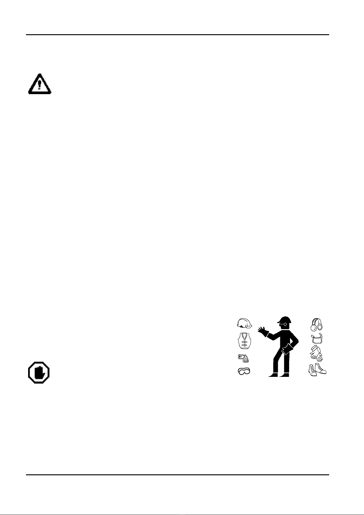
Clothing and protective wear
Avoid wearing loose clothes, rings, watches or anything that
could get entangled inside the rotating parts.
When operating the machine or doing maintenance jobs,
wear a helmet, safety glasses and safety shoes, gloves and
noise protection earmuffs after checking their integrity.
Wear the homologated and certified safety belt
Before operating at height it is necessary to correctly wear the safety belts and to fasten them
to the anchorages of the basket.
The use of the safety belts is compulsory in connection with the local regulatins of every sin-
gle State. In those States where the law does not require the use of holding systems, the choi-
ce is of the employer or/and user.
SELF-PROPELLED TRACKED PLATFORM GOLDLIFT 14.70
HINOWA
12
IMPORTANT
WARNING
13
Safety valves
Never alter and/or tamper with the safety valves and the controls in the main hydraulic
system. HINOWA SPA declines any responsibility for damages to people, things or the
machine when the hydraulic valve standard gauging has been tampered with.
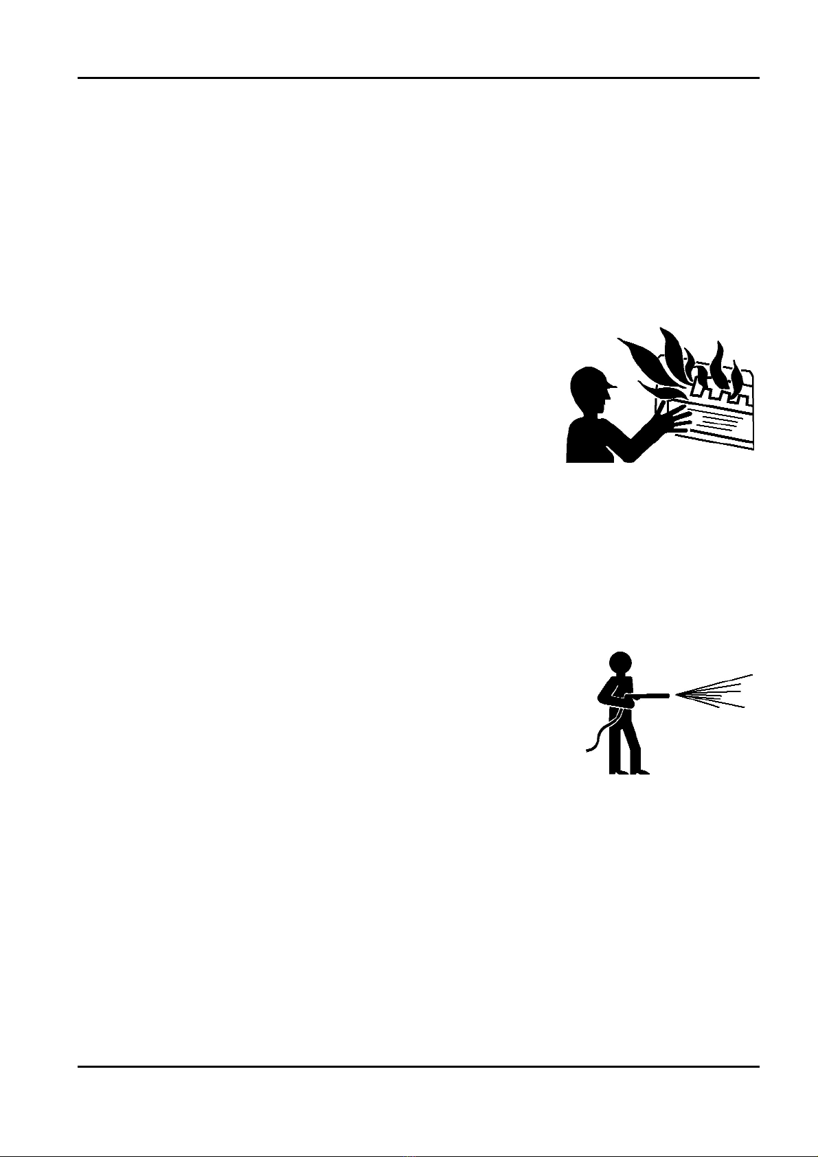
Fire prevention
Keep the engine compartment clean. Remove any pieces of
wood, paper and other flammable products; clean properly
any fuel leaks as they can be potential fire risks.
Petrol is extremely flammable and explosive under certain
conditions. Refuel in a well-ventilated place and when the
engine is off.
Never smoke or cause sparks in the refuelling place or the fuel
storage place.
After refuelling, make sure that the cap is closed safely and
properly.
Take care not to touch the exhaust pipe when it is hot, as it remains hot during the working
of the machine and also after turning off the engine.
Preventing damages caused by washing the machine
When washing the machine do not direct high- pressure jets
onto the electric components. Do not use chemical or petrol
detergents that could cause serious damages to the plastic
components and the paint.
Preventing damages when the machine is at work.
When the machine has been stabilized and starts working, avoid entering in its working
range.
Manoeuvre systematically the controls slowly and regularly. Do not invert movements sharply.
SELF-PROPELLED TRACKED PLATFORM GOLDLIFT 14.70
HINOWA
2.3 SAFETY ADVICE
2.3.1 GENERAL ADVICE
To avoid accidents, before starting work and before doing any
operations of maintenance, read, understand and follow all
the warnings and instructions given in this manual. The
machine operator/user cannot be held responsible if they have
not read this manual and learnt how to manoeuvre the machi-
ne under the supervision of a qualified operator.
Carefully read all the safety warnings in this manual and the
safety signs on your machine.
Keep the safety signs in proper order and replace them when
they are damaged.
Make sure that the new components on the machine have the proper safety signs.
2.3.2 PICTOGRAMS SITUATED ON THE MACHINE
You will find below the description, meaning and location of all the warning, indication and
instruction stickers placed on the machine.
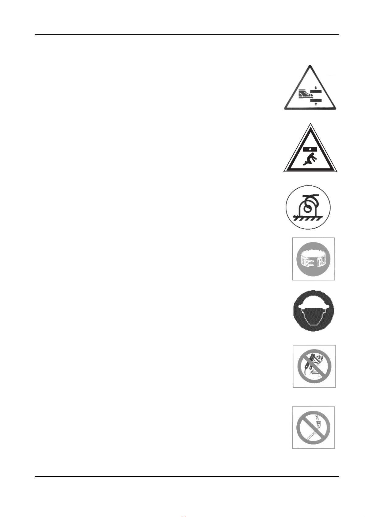
1) Description:
WARNING! READ THE INSTRUCTION AND MAIN-
TENANCE MANUAL BEFORE USING THE MACHI-
NE AND APPROACH THE ELECTRIC COMPONENT
COMPARTMENT.
Location on the machine:
- on the electric component case
- on the basket.
2) Description:
WARNING: KEEP AT SAFETY DISTANCE FROM THE MACHINE.
Location on the machine:
- on the basket
- on the second transmission.
SELF-PROPELLED TRACKED PLATFORM GOLDLIFT 14.70
HINOWA
14
15
3) Description:
WARNING! DANGER OF CRUSHING LOWER LIMBS.
Location on the machine:
- on the stabilisers
- on the crawler.
4) Description:
WARNING! OBJECTS FALLING.
Location on the machine:
- on the basket.
5) Description:
MACHINE FIXING POINTS FOR TRANSPORT.
Location on the machine:
- on fixing points.
6) Description:
FASTEN SEAT BELT.
Location on the machine:
- on the basket.
7) Description:
USE PERSONAL PROTECTION DEVICES.
Location on the machine:
- on the basket.
8) Description:
NEVER DO MAINTENANCE WHEN THE MACHINE IS IN THE
REST POSITION.
Location on the machine:
- on the basket.
9) Description:
NEVER FIX LADDERS, TOOLS OR OTHERS TO THE CONTROL
CAR OF THE PLATFORM TO INCREASE WORKING OUTPUT.
Location on the machine:
- on the basket.
SELF-PROPELLED TRACKED PLATFORM GOLDLIFT 14.70
HINOWA

10) Description:
NEVER WORK NEAR ELECTRIC CABLES (Par. 2.7.1).
Location on the machine:
- on the basket.
11) Description:
NEVER USE THE WORKING PLATFORM AS A LIFT.
Location on the machine:
- on the basket.
12) Description:
WEAR THE PROTECTIVE GLOVES
Location on the machine:
- on the basket.
13) Description:
WEAR SAFETY SHOES
Location on the machine:
- on the basket.
14) Description:
WARNING! 230V.
Location on the machine:
- on the electric differential switch box.
15) Description:
GOLDLIFT 14.70 MAX. LOADS AND ARM RANGES
WITH SINGLE-SEATER BASKET
Location on the machine:
- on the basket.
SELF-PROPELLED TRACKED PLATFORM GOLDLIFT 14.70
HINOWA
16
17
16) Description:
GOLDLIFT 14.70 MAX LOADS AND ARM RANGES
WITH SINGLE-SEATER BASKET (OPTION)
Location on the machine:
- on the basket.
17) Description:
TRANSLATION DISTRIBUTOR CONTROL FUNCTIONS.
Location on the machine:
- near the translation controls.
18) Description:
TRANSLATION DISTRIBUTOR CONTROL FUNCTIONS.
Location on the machine:
- near the translation controls.
19) Description:
DISTRIBUTOR GROUND CONTROL FUNCTIONS OF THE OVERHEAD PART.
Location on the machine:
- near the ground platform con-
trols.
20) Description:
DISTRIBUTOR CONTROL FUNCTIONS OVERHEAD PART ON BASKET GOLDLIFT 14.70.
Location on the machine:
- near the overhead
part controls on the
basket.
SELF-PROPELLED TRACKED PLATFORM GOLDLIFT 14.70
HINOWA
BB BB

21) Description:
OVERHEAD PART GROUND CONTROL SWITCH FROM BASKET.
Location on the machine:
- near the overhead part ground control switch from
basket .
22) Description:
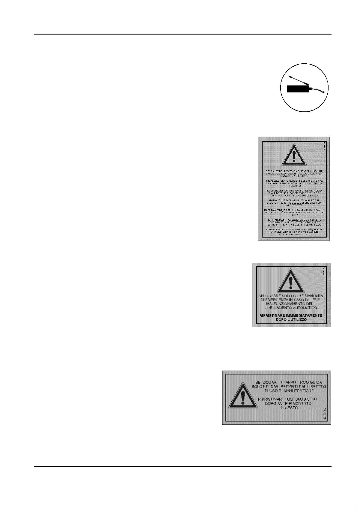
HAND PUMP SWITCH.
Location on the machine:
- near hand pump switch.
23) Description:
GROUND REACTION AND PRESSURE CAUSED BY
THE WEIGHT OF THE MACHINE ON RESTING SURFA-
CES.
Location on the machine:
- on the rubber crawler.
24) Description:
MAXIMUM REACTION AND MAXIMUM PRESSURE INDUCTED
BY ONE STABILISER WITH CAP Diam.300 PLACED ON THE
GROUND.
Location on the machine:
- on the stabiliser.
25) Description:
WARNING: DANGER OF INJURING UPPER LIMBS.
Location on the machine:
- in front of the distributor of the overhead part ground control
and in front of the control place on the basket.
SELF-PROPELLED TRACKED PLATFORM GOLDLIFT 14.70
HINOWA
18
19
26) Description:
RESPECT THE GREASING INTERVARS OF THE INDICATED
PARTS (see page 67-78).
Position on the machine:
- on the thermic engine protection in correspondence with the grease
cup of the slew ring.
27) Description:
TRANSLATION STICKER: It is absolutely forbidden to use
the machine from a different position of the control on the
basket.
Position on the machine:
- Distributor support.
28) Description:
STICKER FOR THE CAGE LEVELLING LOCK
Release only in case of emergency, if the automatic
levelling function does not work correctly; after use,
restore immediately.
Location on the machine:
- overhead part distributor support.
29) Description:
STICKER FOR THE LOCKING OF THE CAGE GUIDE RETAINER CAPS
Release only in the cases specified in the operation
and maintenance manual; after reinstalling the
cage, put back the caps immediately.
Location on the machine:
- cage guide retainer caps
- cage support slide
SELF-PROPELLED TRACKED PLATFORM GOLDLIFT 14.70
HINOWA
Table of contents
Other Hinowa Lifting System manuals


