English
4WILO SE 10/2010
2.4 Safety instructions for the operator
The existing directives for accident prevention must be adhered to.
Danger from electrical current must be eliminated. Local directives or general directives
[e.g. IEC, VDE etc.] and local energy supply companies must be adhered to.
This appliance is not intended for use by persons (including children) with reduced physi-
cal, sensory or mental capabilities, or lack of experience and knowledge, unless they have
been given supervision or instruction concerning use of the appliance by a person respon-
sible for their safety.
Children should be supervised to ensure that they do not play with the appliance.
2.5 Safety instructions for inspection and installation work
The operator must ensure that all inspection and installation work is carried out by author-
ised and qualified personnel, who are sufficiently informed from their own detailed study
of the operating instructions.
Work on the product/unit must only be carried out when at a standstill. It is mandatory that
the procedure described in the installation and operating instructions for shutting down
the product/unit be complied with.
2.6 Unauthorised modification and manufacture of spare parts
Modifications to the product are only permissible after consultation with the manufac-
turer. Original spare parts and accessories authorised by the manufacturer ensure safety.
The use of other parts can nullify the liability from the results of their usage.
2.7 Improper use
The operating safety of the supplied product is only guaranteed for conventional use in
accordance with Section 4 of the operating instructions. The limit values must on no
account fall under or exceed those specified in the catalogue/data sheet.
3 Transport and interim storage
The unit and individual components are delivered on a pallet.
Immediately after receiving the product:
• Check the product for damage in transit.
• In the event of damage in transit, take the necessary steps with the forwarding agent
within the respective time limits.
CAUTION! Risk of property damage!
Inappropriate transport and interim storage can cause damage to the product.
• Transport the product only on the pallet and use only approved handling equipment.
• Make sure the product remains stable and does not suffer any mechanical damage dur-
ing transport.
• Prior to installation, store the product on the pallet in such a manner that it remains dry
and frost-proof and is not exposed to direct sunlight.
• Do not stack.
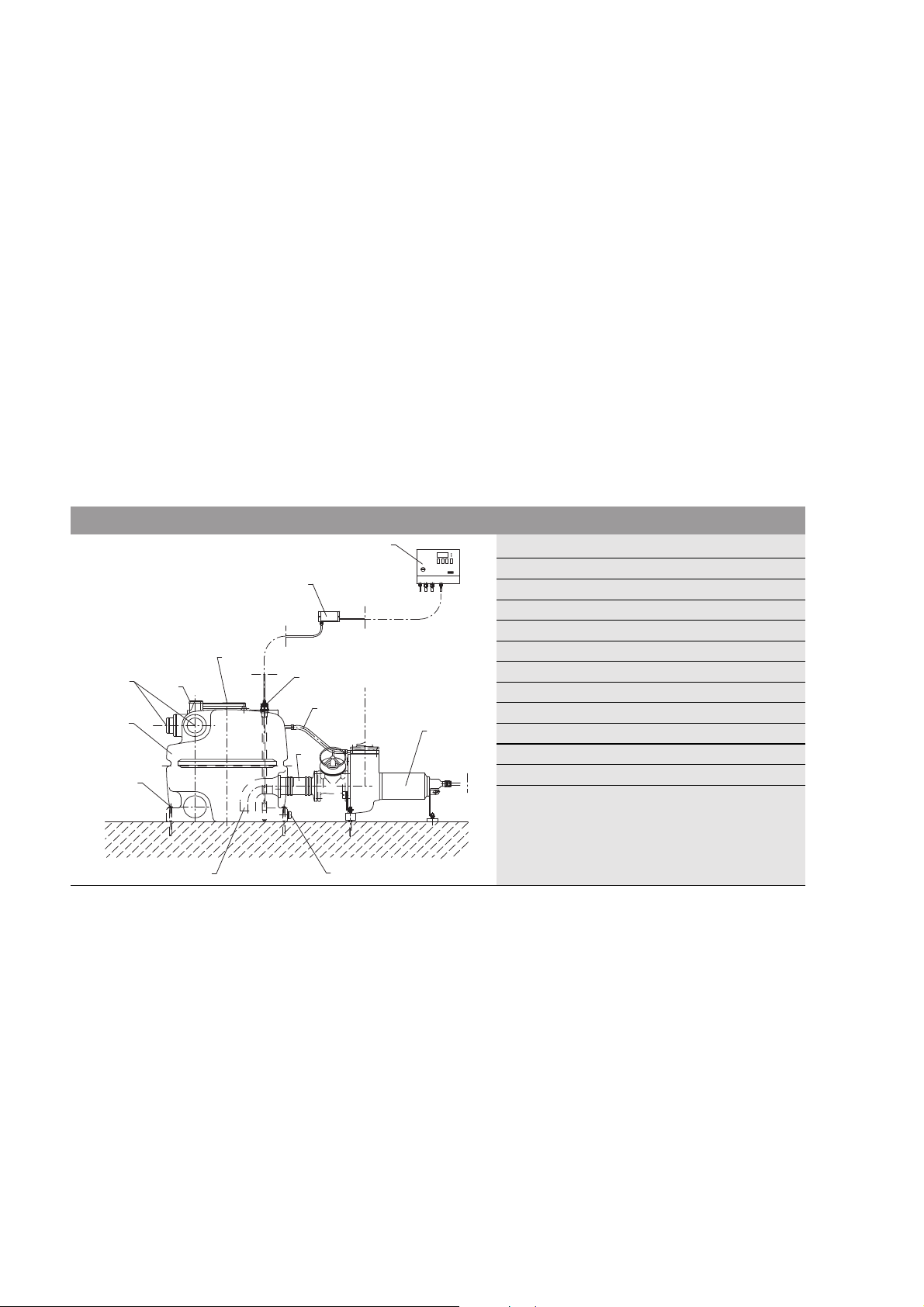
4 Intended use
The DrainLift L XXL sewage lifting unit is an automatic sewage lifting unit according to
EN 12050-1 for collecting and pumping sewage which is free of faeces or contains faeces
for the backflow-proof drainage from discharge points at buildings and sites below the
backflow level.
The unit is only suitable for domestic sewage as defined in EN 12056-1. No explosive or
harmful substances may be introduced in high concentrations, such as solid substances,
debris, ash, garbage, sand, plaster, cement, lime, mortar, fibrous materials, textiles, paper
towels, nappies, cardboard, coarse paper, synthetic resins, tar, kitchen waste, grease, oil,
slaughterhouse waste, disposal of slaughtered animals and animal waste (liquid manure,
etc.), toxic, aggressive and corrosive substances, such as heavy metals, biocides, pesti-
cides, acids, bases, salts, cleaning agents, disinfectants, dishwashing or laundry deter-
gents, and such which have a high degree of foam formation or swimming-pool water.
A grease trap should to be provided if greasy sewage accumulates.
According to EN 12056-1, no sewage from drainage objects may be introduced which lie
above the backflow level and can be drained by means of gravity.