manuals.online logo
Brands
  1. Home
  2. •
  3. Brands
  4. •
  5. Snorkel
  6. •
  7. Lifting System
  8. •
  9. Snorkel S3010E Quick start guide

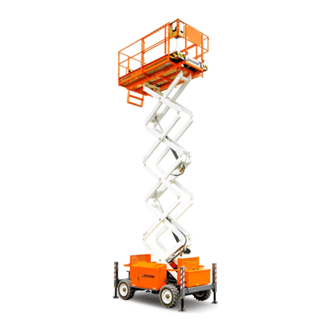
Snorkel S3010E Quick start guide

Serial Number 000000 and after
Part Number 514226-200
October 2014
GENERAL INFORMATION
INTRODUCTION 1-1
OPERATION & SPECIFICATION 1-2
SERVICE & REPAIR 1-3
TROUBLESHOOTING 1-4
SCHEMATICS 1-5
REPAIR PARTS
GENERAL ASSEMBLY 2-1
HOSE KIT 2-2
CHASSIS ASSEMBLY 2-3
COMPONENT TRAY 2-4
POWER PACK ASSEMBLY 2-5
SCISSOR STACK ASSEMBLY 2-6
LIFT CYLINDER ASSEMBLY 2-7
EXTENSION LOCK ASSEMBLY 2-8
PLATFORM ASSEMBLY 2-9
UPPER CONTROL BOX 2-10
ELECTRIC CABLES KIT 2-11
DECALS 2-12
WASTE_REMOVAL_AND_DISPOSAL 2-13
A A
B B
S3010E
www.snorkellifts.com
SERIAL
NUMBER
MODEL
NUMBER
NON-LOADED
MACHINE
WEIGHT
lbs
kg MAXIMUM
WHEEL
LOAD
lbs
kg
ENGINE
POWERED
MODELS
hp
kW BATTERY
POWERED
MODELS V
DRIVE
MOTORS
BATTERIES V
Ah
MONTH / YEAR
OF MANUFACTURE
MAXIMUM
PLATFORM
HEIGHT
RATED NUMBER
OF OCCUPANTS
ft
m
MAXIMUM
DRIVE
HEIGHT
ft
m
MAXIMUM
PLATFORM
LOAD
MAXIMUM
ALLOWABLE
WIND SPEED mph
m/s
MAXIMUM
PLATFORM
REACH
ft
m
514230-001
MAXIMUM
ALLOWABLE
MANUAL FORCE
(SIDE PULL)
lbs
N
Indoors Outdoors
SLOPE SENSOR ALARM SETTING
FRONT
TO BACK deg SIDE
TO SIDE deg
MAXIMUM
OUTRIGGER
LOAD
lbs
kg
MAXIMUM
GRADEABILITY %CHARGER
INPUT V
Axle weights with machine in the stowed position.
lbs
lbs kg
kg
DRIVE AXLE
STEER AXLE
Snorkel,
Vigo Centre, Birtley Road,
Washington, Tyne & Wear,
NE38 9DA, U.K.
Indoors Outdoors
CAUTION
ONLY trained and authorised personnel may operate this machine.Consult the Operation Manual before using this machine.
DO NOT make any changes to this machine, any changes made will invalidate the manufactures warranty and
may contravene legislation.
227kg = 1 Persons
+ 147kg Tools
S3010ECE
-------
495
N/A
N/A
25
----
200
----
N/A
-----
3
1 0
2 2
24
24
105
110/240
----
0
-----
N/A
3
-------
----
---- 235
260
-----
-----
250
NOTE: When contacting SNORKEL for service or parts information, be sure to include the MODEL and
SERIAL NUMBERS from the equipment nameplate. Please find the NAMEPLATE location below.
Page i
SPECIAL INFORMATION
NOTE: Gives helpful information.
D A N G E R
! !
Indicates an imminently hazardous situation which, if not avoided, will result
in severe injury or death.
W A R N I N G
!!
Indicates a potentially hazardous situation which, if not avoided, could result
in severe injury or death.
CAUTION
!!
Indicates a potentially hazardous situation which, if not avoided, may result
in minor or moderate injury.
FOREWORD
HOW TO USE THIS MANUAL
This manual is divided into six sections.
SECTION 1 INTRODUCTION
General description and machine specifications.
SECTION 2 OPERATION AND SPECIFICATIONS
Information on how to operate the work platform and how to prepare it for operation.
SECTION 3 SERVICE AND REPAIR
Preventative maintenance and service information.
SECTION 4 TROUBLESHOOTING
Causes and solutions to typical problems.
SECTION 5 SCHEMATICS
Schematics and valve block diagram with description and location of components. Large sche-
matic drawings may be located in the back of the manual.
SECTION 6 ILLUSTRATED PARTS BREAKDOWN
Complete parts lists with illustrations. Large parts drawings may be located in the back of the
manual.
S3010E SEVICE AND PARTS MANUAL
SECTION 7 WASTE REMOVAL AND DISPOSAL
Flow chart explaining the correct method of hazardous waste disposal.
Foreword -
Page ii
WORKSHOP PROCEDURES
All information contained in this manual is based on the latest product information available at
the time of printing. We reserve the right to make changes at any time without notice. No part of
this publication may be reproduced, stored in retrieval system, or transmitted, in any form by any
means, electronic, mechanical, photocopying, recording, or otherwise, without the prior written
permission of the publisher. This includes text, figures, and tables.
CAUTION
!!
Detailed descriptions of standard workshop procedures, safety principles and
service operations are not included. Note that this manual does contain
warnings and cautions against some specific service methods that could cause
personal injury, or could damage a machine or make it unsafe. Please
understand that these warnings cannot cover all conceivable ways in which
service, whether or not recommended by 3NORKEL, might be done, or of the
possible hazardous consequences of each conceivable way, nor could 3NORKEL
investigate all such ways. Anyone using service procedures or tools, whether or
not recommended by 3NORKEL must satisfy themselves thoroughly that neither
personal safety nor machine safety will be jeopardized. When in doubt, contact
your local distributor or 3NORKEL.
Page 1-1
Section 1
INTRODUCTION
1.1 INTRODUCTION
PURPOSE
The purpose of this service and parts manual is to provide instructions and illustrations for the
operation and maintenance of the S3010E . lekronSybderutcafunam
SCOPE
The manual includes procedures for proper operation, maintenance, adjustment, and repair of
the S3010E as well as recommended maintenance schedules and troubleshooting.
1.2 GENERAL DESCRIPTION
The S3010E consists of the platform, controller, elevating assembly, power / control mod-
ule, and chassis.
Figure 1-1: S3010E Work Platform
PLATFORM
The platform has a reinforced steel floor, 1.11
m (43.75 inch) high guardrailswith midrail, 6
inch (152 mm) toeboards, and an entrance
gate at the front of the platform.
PLATFORM CONTROLLER
The platform controller contains the controls
to operate the machine. It is located at the
side of the platform. A complete explanation
of control functions can be found in Section 2.
ELEVATING ASSEMBLY
The platform is raised and lowered by the ele-
vating assembly. The hydraulic pump, driven
by an electric motor, powers the cylinder.
Solenoidoperated valves control raising and
lowering.
W A R N I N G
!!
DO NOT use the work platform without guardrails properly assembled and in
place.
1.Platform
2.PlatformController
3.ElevatingAssembly
4.Chassis Controls
5.Chassis
1
2
3
4
5
W A R N I N G
!!
DO NOT make any alterations which might affect stability, strength or
performance without the manufacturers consent.
Page 1-2
Introduction1.2 - General Description
CHASSIS
The chassis is a structural frame thatsupports all the components of the S3010Ework platform.
The platform is raised and lowered using a scissors mechanism. Lift is achieved using a single
stage cylinder.
PURPOSE OF EQUIPMENT
The objective of the work platform is to provide a quickly deployable, self- propelled, variable
height work platform to elevate personnel and materials to overhead work areas.
2-2 S3010E –514226-200
Warning
Allpersonnelshallcarefully read,understand andfollow allsafety rulesand operatinginstructions
before operating or performing maintenance on any SNORKEL aerial work platform.
Electrocution
Hazard Tip Over Hazard Collision Hazard Fall Hazard Trapping/Crushing
Hazard
THIS MACHINE IS
NOT INSULATED! NEVER elevate the
platform or drive the
machine while el-
evated unless the
machine is on a firm,
level surface.
NEVER position the
platform without first
checking for over-
head obstructions or
other hazards.
NEVER climb, stand,
or sit on platform
guardrails or midrail.
Beware of crushing
hazardwhenholding
handrails while the
platform is moving
in close proximity to
other objects.
USE OF THE AERIAL WORK PLATFORM: This aerial work platform is intended to lift persons and his tools as well as the
material used for the job. It is designed for repair and assembly jobs and assignments at overhead workplaces (ceilings,
cranes, roof structures, buildings etc.). Uses or alterations to the aerial work platform must be approved by SNORKEL.
THIS AERIAL WORK PLATFORM IS NOT INSULATED! For this reason it is imperative to keep a safe distance from live
parts of electrical equipment! Do not get closer than the minimum distance recommended by National Regulation.
is prohibited! See “Platform Capacity” on page 18 for details.
The use and operation of the aerial work platform as a lifting tool or a crane is prohibited!
NEVER exceed the manual force allowed for this machine. See “Manual Force” on page 18 for details.
DISTRIBUTE all platform loads evenly on the platform.
NEVER fs, bumps, curbs,
or debris; and avoiding them.
OPERATE machine only on surfaces capable of supporting wheel loads.
NEVER operate the machine outdoors or indoors when wind speeds exceed 0 m/s (0 mph).
Do not operate the aerial platform in windy or gusty conditions. Do not add anything to or take anything into the aerial platform
that will increase the wind loading such as billboards, banners, flags, etc.
IN CASE OF EMERGENCY push EMERGENCY STOP switch to deactivate all powered functions.
IF ALARM SOUNDS
Climbing up the railing of the platform, standing on or stepping from the platform onto buildings, steel or prefab concrete
structures, etc., is prohibited!
Dismantling the entry gate or other railing components is prohibited! Always make certain that the entry gate is closed!
It is prohibited to keep the entry gate in an open position when the platform is raised!
To extend the height or the range by placing of ladders, scaffolds or similar devices on the platform is prohibited!
NEVER perform service on machine while platform is elevated without blocking elevating assembly.
INSPECT the machine thoroughly for cracked welds, loose or missing hardware, hydraulic leaks, loose wire connections, and
damaged cables or hoses before using.
VERIFY that all labels are in place and legible before using.
NEVER use a machine that is damaged, not functioning properly, or has damaged or missing labels.
To bypass any safety equipment is prohibited and presents a danger for the persons on the aerial work platform and in its
working range.
NEVER are prohibited or permissible only at the approval by SNORKEL.
AFTER USE, secure the work platform from unauthorized use by turning the keyswitch off and removing key.
Certain inherent risks remain in the operation of this machine despite utilizing proper design practices and safeguarding.
Care must be taken to ensure that the machines meets the requirements of stability during use, transportation, assembly,
dismantling when out of service, testing, or foreseeable breakdowns.
In the event of an accident or breakdown see “Emergency Lowering” on page 12, do not operate the aerial platform if it is
platform back into service.
SAFETY RULES
S3010E –514226-200 2-3
Harness attachment points are provided in the platform and the manufacturer recommends the usage of a fall
restraint harness, especially where required by national safety regulations.
All harness attachment points on SNORKEL vehicles have been tested with a force of 3,650 lbs (16.3 KN)
per person.
See below examples of harness attachment points used on SNORKEL vehicles with their corrosponding rating;
Type 1.
Harness attachment point Type 1. is rated for one lanyard attachment per loop as shown in the
illustrations depending upon platform occupancy rating (see operators manual & decals).
Type 2.
Harness attachment point Type 2. is rated for two
lanyard attachments per loop as shown in the
illustrations depending upon platform occupancy rating
(see operators manual & decals).
Type 3.
Harness attachment point Type 3. is rated for one
lanyard attachment per loop as shown in the
illustrations depending upon platform occupancy rating
(see operators manual & decals).
Top View
2 lanyard
attachments 1 lanyard
attachment
1 lanyard
attachment
Top View
Front View
Type 4.
Harness attachment point Type 4. is rated for one
lanyard attachment per loop as shown in the
illustrations depending upon platform occupancy rating
(see operators manual & decals).
1 lanyard
attachment
NOTE: There can be more harness attachment points per machine than the
maximum number of occupants allowed in a platform. Refer to
the platform decal & specifications table listed in the operators
manual for the correct occupancy rating before use.
Type 1.
Top View Top View
2 lanyard
attachments
Top View
1 lanyard
attachment
Top View
1 lanyard
attachment
Introduction
2-4 S3010E –514226-200
Introduction
This manual covers the S3010E Aerial Work Platforms.
This manual must be stored on the machine atall times.
Read,understandand followallsafetyrulesandoperating
instructions before attempting to operate the machine.
When contacting SNORKEL for service or parts infor-
mation, be sure to include the MODEL and SERIAL
NUMBERS from the equipment nameplate. Should the
nameplate be missing, the SERIAL NUMBER is also
stamped on the front of the chassis.
Upper Controls
Document Holder
Fall Restraint Harness
Attachment point
Platform
Scissor Assembly
Drive & Steer Wheels
Component Tray
(Hydraulic Reservoir/Pump/batteries)
Lower Controls &
Battery Charger
Emergency Lowering
valve
Entry Step
Forklift Pockets
Chassis
Toeboards
Guardrails
Entry Gate
Special Limitations
S3010E –514226-200 2-5
Special Limitations
Travel with the platform raised is limited to creep speed
range. Elevating the platform is limited to firm, level
surfaces only.
Danger
The elevating function shall ONLY be used when the
work platform is level and on a firm surface.
The work platform is NOT intended to be driven over
uneven, rough, or soft terrain.
Platform Capacity
One person andtools may occupythe platform whenthe
machineisindoors only.Themaximumplatform capacity
for the aerial platform is stated in the “Specifications” on
page 18.
Danger
DO NOT exceed the maximum platform capacity or
the platform occupancy limits for this machine.
Manual Force
Manual force is the force applied by the occupants to
objects such as walls or other structures outside the
work platform.
In zero wind conditions the maximum allowable manual
force is limited to 200 N (45 lb).
Danger
DO NOT exceed the maximum amount of manual
force for this machine.
Drive/Lift Level Sensor Interlock
Theaerial platformdriveand liftfunctionsareinterlocked
through a level sensor system. The drive/lift level sensor
interlockoperateswhen theplatformis elevatedapproxi-
mately 1.5 m (5′).
If the chassis is tilted more than 2 degrees side-to-side
or more than 2 degrees front-to-rear while the platform is
elevated, the drive and lift functions will not operate and
an alarm will sound.
Lower the platform and drive to a level surface when the
drive/lift level sensor alarm sounds.
The drive/lift level sensor system is for added protection
anddoesnotjustifyoperating onanythingotherthanfirm,
flat, level surfaces.
Lowering Alarm
When the joystick is moved out of neutral to lower the
platform, the alarm emits a loud beeping sound to warn
personnel in the work area to stand clear.
Danger
Pinch points exist on the scissors structure. Death
or serious injury will result if the scissors structure
lowers onto personnel within the scissors arms or
under the raised platform. Stand clear while raising
and lowering the platform.
Be careful when lowering the platform. Keep hands and
fingers away from the scissors structures components.
Lowering Interrupt
When the platform is lowered to about 1.5 m (5′) lower-
ing stops. The platform will not lower for three seconds
regardless of the control position to allow personnel to
clear the area of the scissors before the platform com-
pletely lowers.
Centerthecontrolinneutraltoresettheloweringfunction,
then continue to lower the platform.
Danger
The aerialplatform can tipoverif it becomesunstable.
Death or serious injury will result from a tip-over ac-
cident. Do not exceed the capacity values indicated
on the platform rating placard.
Controls and Indicators
2-6 S3010E –514226-200
Danger
Pinchpointsmayexistbetweenmovingcomponents.
Death or serious injury will result from becoming
trappedbetweencomponents,buildings,structures,
or other obstacles. Make sure all personnel stand
clear whileoperating the aerial platform.
•Controls to position the platform are located on the
lower control panel on the chassis and on the upper
control panel in the platform.
•Controlstodrivetheaerialplatform arelocatedon the
upper control panel only.
Lower Controls
The lower controls (refer to Figure 1) are located on the
left side of the chassis. Only platform functions can be
operated from the lower controls.
The following are located on the lower control panel:
•Emergency stop button
•Control selector switch
•Ground operation switch
•Platform raise/lower switch
Emergency Stop Button
The emergency stop is a two-position red push button.
•Push the button inward to disconnect power to all
control circuits.
•Pull the button outward to restore power.
Control Selector Switch
Insert the key into the control selector switch.
•Turn the switchtothelower controlspositiontooper-
ate aerial platform functions from the lower controls.
The upper controls will not operate while the control
selector is in the lower position.
•Turn the switch to the upper controls position to
operate the aerial platform functions from the upper
controls.
•Inthecenterposition,aerialplatformfunctionswillnot
operate from the lower or upper controls.
Ground Operation Switch
Thegroundoperationswitchpreventsplatformmovement
if the platform raise/lower switch is accidentally moved.
This switch is spring returned tothe off position.
Hold the ground operation switch upward continually to
operate the machine from the lower controls.
Controls and Indicators
The operator shall know the location of each control and
indicator and have a thorough knowledge of the function
and operation of each before attempting to operate the
machine.
Figure 1 – Lower Controls and Indicators
1. Battery charging point
2. Control selector switch
3. Battery Charge indicator
4. Emergency stop button
5. Platform raise/lower switch
6. Ground Operation switch
Figure 2 – Upper Controls and Indicators
7. Drive/lift selector switch
8. Enable trigger (Front of Joystick)
9. Joystick
10. Low battery indicator
11. Horn button
12. Emergency stop button
7
8
9
10
11
0
CHARGER
513924-002
12
3
4
5 6
12
Controls and Indicators
S3010E –514226-200 2-7
Platform Raise/Lower Switch
The platform raise/lower switch is used to raise or lower
the platform. The switch is spring returned to the center
off position.
• Hold the switch upward to raise the platform.
• Hold the switch downward to lower the platform.
• An alarm will sound as the platform lowers.
Upper Controls
The upper controls (refer to Figure 2) are located on the
controlpanelat theplatform.Platformand drivefunctions
can be operated from the upper controls.
Warning
Thepotential for anaccident increases fromimprop-
erly driving or steering the aerial platform. Death or
serious injury could result from such accidents.
The following controls are located on the upper control
panel:
• Emergency stop button
• Drive/lift selector switch
• Joystick to control platform lift, drive, and steer
• Horn button
• Enable Trigger
Emergency Stop Button
The emergency stop is a two-position, red push button
on the front of the upper control panel.
• Push the button inward to disconnect power from all
control circuits at the upper controls.
• Twist the button clockwise to restore power.
Pushthebutton inwhentheuppercontrolsarenot inuse
to help protect against unintentional platform operation.
Drive/Lift Selector Switch
The drive/lift selector switch is used to select either
machine drive or lift functions. Both functions can not be
operated at the same time.
• Place the drive/liftselector switch inthe drive position
to drive the aerial platform using the joystick. The
platform will not raise or lower while driving.
• Place the drive/lift selector switch in the lift position to
raise and lower the platform using the joystick.
Joystick
Use the joystick to operate the following functions:
• Aerial platform steering
• Aerial platform drive and speed
• Platform raise/lower and speed
Movement of the joystick in a given direction produces
a corresponding movement of the aerial platform. The
steering and drive functions may be operated separately
or simultaneously.
Horn Button
The horn button is on the top of the upper control
panel.
Press the button to sound the horn.
Enable Trigger
The trigger preventsaccidental operationof themachine
from the upper controls and must be held in to operate
the machine.
Pre-Operation Safety Inspection
2-8 S3010E –514226-200
Pre-Operation Safety Inspection
Note
Carefully read, understand and follow all safety rules,
operatinginstructions,labelsand NationalSafetyInstruc-
tions/Requirements. Perform the following steps each
day before use.
1. Open the tray and inspect for damage, fluid leaks or
missing parts.
2. Checkthelevelofthe hydraulicfluidwiththeplatform
fully lowered. The fluid level must be within the mini-
mum and maximum level indicated on the dipstick
which can be found on the bottom of the lling cap.
Add recommended hydraulic fluid if necessary. See
“Specifications” on page 18.
3. Check that the fluid level in the batteries is correct.
See “Battery Maintenance” on page 15.
4. Verify that the batteries are charged.
5. Check that the AC extension cord has been discon-
nected from the outlet on the side of the chassis.
6. Checkthatallguardrailsareinplaceand allfasteners
are properly tightened.
7. Inspect the machine thoroughly for cracked welds
and structural damage, loose or missing hardware,
hydraulic leaks, damaged control cable and loose
wire connections.
System Function Inspection
S3010E –514226-200 2-9
System Function Inspection
Refer to “Controls and Indicators” on page 6 for the loca-
tions of various controls and indicators.
Warning
STAND CLEAR ofthework platformwhileperforming
the following checks.
Before operating the machine, survey the work area
for surface hazards such as holes, drop-offs, bumps
and debris.
Check in ALL directions, including above the work
platform, for obstructions and electrical conduc-
tors.
1. Move the machine, if necessary, to an unobstructed
area to allow for full elevation.
2. PulltheLowerControlEmergency StopSwitchtothe
ON position.
3. Turn the Upper Control Emergency Stop Switch
clockwise to the ON position.
4. Visually inspect the scissors structure, lift cylinder,
andhosesfor crackedweldsand structuraldamage,
loose hardware, hydraulic leaks, loose wire connec-
tions, and erratic operation. Check for missing or
loose parts.
5. Hold the ground operation switch upward. Test each
machinefunctionfrom thelowercontrolstation(refer
to Figure 1).
6. Test the emergency lowering system for proper op-
eration.
7. Push the Lower Control Emergency Stop Button to
check for proper operation. All machine functions
should be disabled. Pull the Lower Control Emer-
gency Stop Button outward to resume.
8. Enter the platform and close the gate.
9. Check that the route is clear of obstacles (persons,
obstructions, debris), is level, and is capable of sup-
porting the wheel loads.
10. Test each machine function from the upper control
station by engaging the interlock and operating the
function controls (refer to Figure 2).
11. Push the Upper Control Emergency Stop Button to
check for proper operation.All platform control func-
tions should be disabled. Turn the Upper Control
Emergency Stop Button clockwise to resume.
Operation
2-10 S3010E –514226-200
Operation
Theaerialplatformmaybe operatedfromeitherthelower
or upper controls.
Danger
The aerialplatformisnot electrically insulated.Death
or serious injury will result from contact with, or in-
adequate clearance from, an energized conductor.
Do not go closer than the minimum safe approach
distance as defined by national safety regulations.
Pinch points mayexistbetweenmoving components.
Death or serious injury will result from becoming
trapped betweencomponents,buildings,structures,
or other obstacles. Make sure there is sufficient
clearance around the machine before moving the
chassis or platform. Allow sufficient room and time
to stop movement to avoid contact with structures
or other hazards.
The aerialplatform can tipoverif it becomesunstable.
Death or serious injury will result from a tip-over ac-
cident. Operatetheaerialplatformon afirm,flat,level
surface.Avoidtravelspeedsand/orrough terrainthat
could causesuddenchangesinplatformposition. Do
not drive or position the aerial platform for elevated
use near any drop-off, hole, slope, soft or uneven
ground, or other tip-over hazard. Do not raise the
platform in wind speeds above 0 m/s (0 mph).
Theplatformrated workloadisthe totalweightofthe per-
sonnel and equipment that may be lifted in the platform.
Theworkloadsarestatedontheplatformratingplacardat
the entrance to the platform and page 18 of this manual.
Danger
The aerialplatform can tipoverif it becomesunstable.
Death or serious injury will result from a tip-over ac-
cident. Do not exceed the capacity values indicated
on the platform rating placard.
Capacity values indicate the rated lifting capacity and do
not indicate aerial platform stability.
The operator bears ultimate responsibility for ensuring
thattheaerial platformisproperly setupfor theparticular
conditions encountered.
Preparing for Operation
Usethefollowingprocedureto preparetheaerialplatform
for operation:
1. Perform a pre-operation safety and system function
inspection.
2. Close and latch the component tray.
Lower Controls
Onlythe platformraise andlower functionsmaybeoper-
ated from the lower controls. The lower controls may be
usedforinitial setupoftheaerialplatform,and fortesting
and inspection.
Usethefollowing proceduretoraiseor lowertheplatform
using the lower controls.
1. Pull the emergency stop button outward (refer to
Figure 1).
2. Insertthekeyintothecontrol selectorswitchandturn
the switch to the lower controls position.
3. Hold the ground operation switch upward. Hold the
platform raise/lower toggle switch up to raise the
platform and down to lower it.
4. Release the toggle switch to stop movement.
Upper Controls
The upper controls may be used for driving and position-
ing the aerial platform while on the job.
Before operating the upper controls, properly set up the
aerial platform as described under Preparing for Opera-
tion.
Warning
Thepotential for anaccident increases fromimprop-
erly driving or steering the aerial platform. Death
or serious injury could result from such accidents.
Make sure the upper control panel is facing the front
of the platform, attached to the guardrail, and inside
the platform rails.
Usethefollowingprocedureto operatetheaerialplatform
from the upper controls:
1. From the lower controls, pull the emergency stop
button outward (refer to Figure 1).
2. Insertthekeyintothecontrol selectorswitchandturn
the switch to the upper controls position.
Note
The upper controls will not operate while the control
selector is in the lower position.
3. Enter the platform and secure the gate.
4. From the upper controls, turn the emergency stop
button clockwise to the on position (refer to Figure
2).
5.
The aerial platform may be driven and the platform
may be raised and lowered from the upper controls.
Operation
S3010E –514226-200 2-11
Platform
Usecare when entering and exiting the platform toavoid
slipping and/or falling. Securely close the safety gate
when the platform is occupied.
Raising and Lowering
The raise speed is proportional to the joystick position.
The further the joystick is moved, the faster the platform
raises. There is only one lowering speed.
1. Place the drive/lift selector switch (refer to Figure 2)
in the lift position.
2. Squeeze the trigger on the joystick.
To raise the platform, slowly push the joystick
forward until the desired height is reached.
To lower the platform, pull the joystick backward.
Lowering Interrupt
When the platform is lowered to about 1.5 m (5′) lower-
ing stops. The platform will not lower for three seconds
regardless of the joystick position.
Center the joystick in neutral to reset the lowering func-
tion, then continue to lower the platform.
Danger
Theaerialplatformcantip overifitbecomes unstable.
Death or serious injury will result from a tip-over ac-
cident. Do not exceed the capacity values indicated
on the platform rating placard.
Driving and Steering
Danger
Theaerialplatformcantip overifitbecomes unstable.
Death or serious injury will result from a tip-over ac-
cident. Do not drive an elevated aerial platform on
soft, uneven, or sloping surfaces. Do not drive on
grades that exceed 0percent.
Warning
Death or serious injury could result from improperly
driving or steering the aerial platform. Read and un-
derstand the information in this manual and on the
placardsanddecalson themachine beforeoperating
the aerial platform on the job.
Use the following procedure to operate the drive and
steer functions.
1. Place the drive/lift selector switch (refer to Figure 2)
in the drive position.
2. Squeeze the trigger on the joystick.
3. Push the drive joystick forward to move the chassis
forward.Pullthejoystickbackwardtomovethechas-
sis backward. The drive speed is proportional to the
joystick position.
4. To stop drive motion, return the joystick to neutral.
Note
To make an emergency stop push the emergency stop
button inward to apply the parking brakes.
5. To steer to the right, hold the joystick to the right. To
steer tothe left, hold the joystick tothe left.
Operation
2-12 S3010E –514226-200
Drive Speeds
Thedrivespeedisproportionaltothejoystickposition.The
further the joystick is moved, the faster the travel speed.
Always slow down before traveling over rough terrain or
surfaces.
Drivespeedrangesare interlockedthroughlimitswitches
that sense the platform position.
• When the platform is elevated below approximately
1.5 m (5′) the aerial platform may be driven within the
full range of drive speeds.
• When the platform is elevated above 1.5 m (5′) only
the slowest drive speed will work.
Warning
The potential for an accident increases when safety
devices do not function properly. Death or serious
injury could result from such accidents. Do not alter,
disable, or override any safety device.
Do not use the aerial platform if it drives faster than 0.6
km/h (0.4 mph), which is 5.3 m (7′ 7″) in 30 seconds,
when elevated above 1.5 m (5′).
Drive/Lift Level Sensor Interlock
When the platform is elevated above 1.5 m (5′), lift and
drive functions are interlocked through a level sensor
system. If the chassis is tilted more than 2 degrees side-
to-side or front-to-rear, platform raise and drive functions
are disabled and an alarm sounds when those controls
are activated.
If the drive/liftlevel sensor interlockshuts offthe platform
raise and drive functions, lower the platform and drive to
a level surface.
Component Tray
Batteries and hydraulic components are enclosed in the
component tray on the left side of the chassis.
Danger
The aerialplatform can tipoverif it becomesunstable.
Death or serious injury can result from a tip-over
accident. Do not open the tray when the platform is
raised more than 2.4 m (8′).
Toopen thetray,lift uponthelatch andpullthetrayopen.
Emergency Lowering
Use the following procedure to operate the emergency
lowering system.
Warning
The potential for an accident increases when safety
devices do not function properly. Death or serious
injury can result from such accidents. Immediately
push theemergency stop buttoninward todisablethe
control systembefore usingtheemergency lowering
system in the event of an emergency.
1. Immediatelypushtheemergency stopbuttoninward
todisablethe controlsystemintheeventofan emer-
gency.
2. Make sure there is nothing in the way to obstruct the
platform when it lowers.
• Push downward on the lever to lower the platform
(refer to Fgure 3).
3. Make certain the lever/handle is fully released and
the emergency lowering valve is fully closed before
operating the aerial platform.
Figure 3 – Emergency Lowering Control
Emergency
Lowering Lever
Transporting the Machine
S3010E –514226-200 2-13
Transporting the Machine
Preparing for Transportation
Usethefollowingprocedureto preparetheaerialplatform
for transportation.
1. Remove any unnecessary tools, materials, or other
loose objects from the platform.
2. Close and latch the component tray.
Transporting
Theaerialplatform maybemovedon atransportvehicle.
Depending on the particular situation, the aerial platform
may be lifted with a forklift, driven, winched, or hoisted
onto a vehicle such as a truck or trailer. Lifting with a
forklift is the preferred method.
The equipment used to load, unload, and transport the
aerial platform must have adequate capacity. The empty
vehicleweightis listedin“Specifications”onpage 18and
is stamped on the serial number placard.
The user assumes all responsibility for:
• Choosing the proper method of transportation.
• Choosing the proper selection and use of transporta-
tion and tie-down devices.
• Making sure the equipment used is capable of sup-
porting the weight of the aerial platform.
• Makingsureall manufacturer’sinstructionsandwarn-
ings, regulations and safety rules of their employer,
the DOT, and/or any other state or federal law are
followed.
Lifting With a Forklift
Use the followingprocedure to liftthe aerial platformwith
a forklift.
1. Properly stow the aerial platform.
2. Removeallpersonnel,tools,materials,or otherloose
objects from the platform.
3. Insert the forklift forks into the pockets on the side of
the machine.
Caution
Lifting the aerial platform with the forklift forks posi-
tionedimproperly can produce enoughforceto dam-
age machine components. When lifting the machine
with a forklift, only use the designated lift points.
4. Donotraisetheaerialplatformhigherthannecessary
to transport it. Drive the forklift slowly and carefully
when transporting the aerial platform.
Winching
Use a winch to load and unload the aerial platform on
rampsthatexceedthemachinegradeabilityspecification.
Awinchmayalsobeusedwhenpoortraction,unevensur-
faces,orsteppedramptransitionmakedrivinghazardous.
Use the following procedure to winch the aerial platform
onto the transport vehicle.
1. Position the transport vehicle so the aerial platform
will not roll forward after it is loaded.
2. Remove any unnecessary tools, materials, or other
loose objects from the platform.
3. Drive the machine to the foot of the loading ramp
with the front wheels nearest the ramp. Make sure
the machine is centered with the ramps and that the
wheels are straight.
4. Properly stow the aerial platform.
5. Chock the wheels to prevent uncontrolled motion of
the aerial platform.
6. Insert the winch line through the folk lift points on the
front of the chassis.
Note: this machine is not fitted with a brake release, to
releasethewheelswhilewinchingthemachineneeds
tobefullyopperational withthejoystickintheforward
position.
7. From the lower controls, pull the emergency stop
button outward.
8. PlacetheControlSelectorSwitchupwardintheupper
controls position.
Note
The upper controls will not operate while the control
selector is in the lower position.
9. Enter the platform and close the gate.
10.From the upper controls, pull the emergency stop
button outward.
11. Remove the wheel chocks and use the joystick and
winch together to position the aerial platform on the
transport vehicle.
Warning
Damage to the aerial platform and/or drive system
may occur if the joystick is not held in the forward
position while the winching process is being carried
out .
Transporting the Machine
2-14 S3010E –514226-200
Driving Danger
Theaerialplatformcantip overifitbecomes unstable.
Death or serious injury will result from a tip-over ac-
cident.Donotdrive onrampsthat exceed25 percent
grade, or where conditions of the ramp could cause
driving to behazardous.
Drive the aerial platform onto the transport vehicle if a
winch is not available and the ramp incline is within the
grade capability of the aerial platform.
Use the following procedure to drive the aerial platform
onto the transport vehicle.
1. Position the transport vehicle so the aerial platform
will not roll forward after it is loaded.
2. Chock the vehicle wheels so itcannot roll away from
the ramp while the aerial platform is loaded.
3. Remove any unnecessary tools, materials, or other
loose objectsfrom the platform.
4. Fully lower the platform.
5. Drive the aerial platform to the foot of the loading
ramp with the front wheels nearest the ramp. Make
sure the aerial platform is centered with the ramps
and that the steering wheels are straight.
6. Drivetheaerialplatformonoroffthetransportvehicle
in a straight line through the grade transitions with
minimal turning.
Hoisting
Use suitable straps through the fork lift channels and a
suitable fixture to keep the straps clear of the guardrails
when hoisting the aerial platform. Machine damage can
occur if the sling is attached anywhere else.
Warning
Thepotentialforanaccidentincreaseswhentheaerial
platform is lifted using improper equipment and/or
liftingtechniques.Deathorseriousinjurycouldresult
fromsuch accidents. Use proper equipment and lifting
techniques when lifting the aerial platform.
Know the weight of the aerial platform and the capacity
of the lifting devices before hoisting.
•Lifting devices include the hoist or crane, chains,
straps,cables,hooks,sheaves,shackles,slings,and
other hardware used to support the machine.
•Theemptyvehicleweightis stampedontheserial num-
on page 2-18.
The user assumes all responsibility for:
•Making sure the equipment used is capable of sup-
porting the weight of the aerial platform.
•Makingsureall manufacturer’sinstructionsandwarn-
ings, regulations and safety rules of their employer
and/or any state or federal law are followed.

Other Snorkel Lifting System manuals

Snorkel TM12 Series User manual

Snorkel

Snorkel TM12 Series User manual

Snorkel TB42 User manual

Snorkel

Snorkel TB42 User manual

Snorkel MHP 13/35 Mark II Use and care manual

Snorkel

Snorkel MHP 13/35 Mark II Use and care manual

Snorkel S2255RTE Owner's manual

Snorkel

Snorkel S2255RTE Owner's manual

Snorkel TB80 User manual

Snorkel

Snorkel TB80 User manual
Snorkel AB85J Owner's manual

Snorkel

Snorkel AB85J Owner's manual

Snorkel S39770RT Owner's manual

Snorkel

Snorkel S39770RT Owner's manual

Snorkel S2646E User manual

Snorkel

Snorkel S2646E User manual

Snorkel MHP13AT User manual

Snorkel

Snorkel MHP13AT User manual

Snorkel UL40 Quick start guide

Snorkel

Snorkel UL40 Quick start guide

Snorkel MB26J User manual

Snorkel

Snorkel MB26J User manual
Snorkel TL37J User manual

Snorkel

Snorkel TL37J User manual

Snorkel SL20 User manual

Snorkel

Snorkel SL20 User manual

Snorkel SR2770 User manual

Snorkel

Snorkel SR2770 User manual

Snorkel TB66J Owner's manual

Snorkel

Snorkel TB66J Owner's manual

Snorkel TL49J User manual

Snorkel

Snorkel TL49J User manual

Snorkel SR2770 Use and care manual

Snorkel

Snorkel SR2770 Use and care manual

Snorkel TM12 Series User manual

Snorkel

Snorkel TM12 Series User manual
Snorkel AB60J User manual

Snorkel

Snorkel AB60J User manual

Snorkel MHP15/44 User manual

Snorkel

Snorkel MHP15/44 User manual

Snorkel A38E Quick start guide

Snorkel

Snorkel A38E Quick start guide
Snorkel SP20 User manual

Snorkel

Snorkel SP20 User manual

Snorkel SL26 Series Quick start guide
Snorkel

Snorkel SL26 Series Quick start guide

Snorkel S3215E User manual

Snorkel

Snorkel S3215E User manual

Popular Lifting System manuals by other brands

Vestil UNI owner's manual

Vestil

Vestil UNI owner's manual

Lippert Components Power Gear owner's manual

Lippert Components

Lippert Components Power Gear owner's manual

Sealey MC680A instructions

Sealey

Sealey MC680A instructions

HOMECARE PRODUCTS EZ-ACCESS TRIFOLD Advantage Series Instructions for use

HOMECARE PRODUCTS

HOMECARE PRODUCTS EZ-ACCESS TRIFOLD Advantage Series Instructions for use

Genie Lift Tools GS-2669 Operator's manual

Genie

Genie Lift Tools GS-2669 Operator's manual

Dhollandia DH-AI12.04.01 installation manual

Dhollandia

Dhollandia DH-AI12.04.01 installation manual

Ravaglioli KPH 370.42K Translation of the original instructions

Ravaglioli

Ravaglioli KPH 370.42K Translation of the original instructions

EAE EE-612E Installation, operation, and parts manual

EAE

EAE EE-612E Installation, operation, and parts manual

Atlas PV-10PX Installation & operation manual

Atlas

Atlas PV-10PX Installation & operation manual

probst VZ-II operating instructions

probst

probst VZ-II operating instructions

Invacare Aquatec Disk Assembly instructions

Invacare

Invacare Aquatec Disk Assembly instructions

Molift QUICK RAISER Operation manual

Molift

Molift QUICK RAISER Operation manual

EINHELL TC-EH 1000 Original operating instructions

EINHELL

EINHELL TC-EH 1000 Original operating instructions

Hubbell EH-85 manual

Hubbell

Hubbell EH-85 manual

Liko Viking S Instruction guide

Liko

Liko Viking S Instruction guide

Ravaglioli RAV232 NF manual

Ravaglioli

Ravaglioli RAV232 NF manual

stertil ST1175 Service manual

stertil

stertil ST1175 Service manual

Challenger Lifts E15 Installation, operation & maintenance manual

Challenger Lifts

Challenger Lifts E15 Installation, operation & maintenance manual

manuals.online logo
manuals.online logoBrands
  • About & Mission
  • Contact us
  • Privacy Policy
  • Terms and Conditions

Copyright 2025 Manuals.Online. All Rights Reserved.