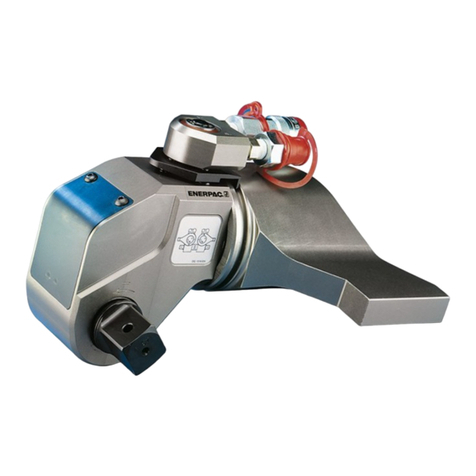
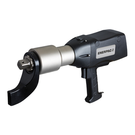
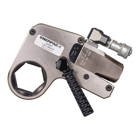
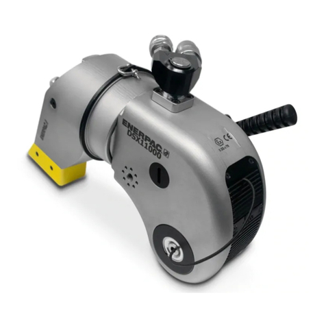
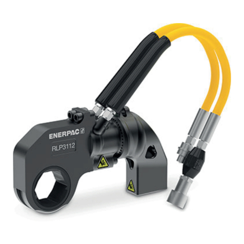
SQD Series Torque Wrench
14. Once the Cap Screw is removed, use the pliers
to pull the Compression Member (item 2.9) from
the Piston Assembly. The Compression Member
(item 2.9) has a ball bearing in the threaded
hole, and is connected to the Piston Rod, (item
2.11) with a internal O-ring.
15. Push the Piston Rod (item 2.11) and Piston
Bottom, (item 2.12 ) out the back of the wrench
using a punch. A hammer is not necessary as
the Piston Assembly should come out freely.
16. Gently pull the Piston Bottom (item 2.12) from
the Piston Rod (item 2.11). It is also connected
together by an internal O-ring.
17. Remove the two bearings, Glyd-ring and O-ring
from the Piston Assembly.
18. To remove the two drive bearings (item 3.4), use
a socket and soft blow hammer to carefully drive
them out.
19. Use a brass pick to remove the Glyd-ring,
Bearing and O-rings in the Wrench Housing
(item 2.6).
INSPECTION
1. Examine the Wrench Housing’s interior, (item
2.6) for signs of wear or scratches.
2. Inspect the Compression Bolt (item 2.8) and
Ratchet Lever (item 3.8) for signs of excessive
wear.
3. Examine the Piston Assembly for signs of wear
and scratches that may cause leakage.
4. Inspect the Ratchet Wheel (item 3.5) and the
Ratchet Block (item 3.2) for broken teeth, cracks
and wear.
5. Examine all O-rings, Bearings, and Glyd-rings
for wear, scratches and possible deformation
from incorrect fluids.
6. Make sure all threads are in good condition.
ASSEMBLY
1. Replace two O-rings, bearing and Glyd-ring in the
Wrench Housing (item 2.6). To install the Glyd-
ring, form the ring as shown in Figure 1, and
then use round stock to reform the ring.
Note: When replacing seals, it is important to
use the grease provided in the repair kit when
reassembling.
2. Replace the two bearings, two O-rings, and the
Glyd-ring on the Piston Rod (item 2.11) and
Piston Bottom (item 2.12). Then push the two
pieces together.
3. Gently push the Piston Assembly into the
Wrench Housing (item 2.6), being careful not to
damage any seals or bearings.
4. Through the front of the wrench, push the
Compression Member (item 2.9), into the Piston
Rod (item 2.11). Position the larger end of the
Compression Member toward the top of the
wrench.
5. Reinstall the Cap Screw in the Piston Assembly,
while holding the Compression Member (item
2.9) in place with a pliers. Be careful not to
damage it.
6. If replacing drive bearings, use a socket to
push them back into place using a soft blow
hammer. Be careful not to damage bearings
during assembly.
7. The Compression Bolt (item 2.8) has a slight
offset hole to one side. The hole should face the
top of the Ratchet Lever (item 3.8) when rein-
stalling into the clearance hole.
8. Place together the Ratchet Wheel (item 3.5) and
Ratchet Block (item 3.2). Slide these pieces into
the Ratchet Lever (item 3.8) with the springs.
Note: Make sure the Ratchet Wheel and
Block are both centered in the Ratchet Lever.
9. Push the Compression Member (item 2.9) into
the wrench so that the Ratchet Lever (item 3.8)
can be reinstalled.
10. Before installing the Ratchet Lever (item 3.8),
make sure the ball bearing is in the threaded
hole of the Compression Member (item 2.9).
11. Install the Ratchet Lever (item 3.8) into the
Wrench Housing (item 2.6).
2
