BEHR behrotest K8 User manual

059111
behrotest®K8 / K12 / K20/
K16 / K24 / K40
Digestion Unit
User‘s Manual

059111
Please read this operating manual carefully before starting use of your new K8 / K12 / K20 / K16 / K24 / K40
digestion unit!
The manual introduces you to the use of the apparatus with clear and simple guidance.
For reasons of safety in use of the system, please follow all safety warnings carefully. These are designated in the
text by a warning symbol .
Additional information, which is useful and important for an understanding of the manner of operation of the
apparatus, is denoted by a stripe in the margin.
We wish you success in the use of the

059111
Safety Advice
Danger of burns! The digestion tubes and the inner zone of the heating block get hot!
Never touch the hot glasses or the area of the heating block around the digestion tubes with the
bare hands.
Danger of electric shock!
Always install all cables in such a way that they cannot come into contact with the hot inner zone
of the heating block; they could otherwise smoulder through! Always ensure that no liquids can
come into contact with cable connections or the interior of the heating block! Always withdraw
the mains plug before opening the unit! Repairs on electrical, electronic and mechanical modules
of this appliance may be performed only by authorized specialist staff.
Danger of injury in case of breakage of glass! Always adhere to your professional association's
regulations when handling glass parts!
Care is required when using and handling acids and alkalis! Danger of corrosive burns and
injuries! ! Adhere to the current Hazardous Substances Ordinance!
Hazard from toxic gases!
During the Kjeldahl digestion, vapours of sulfuric acid (and other toxic gases) are set free. They
could harm your health and damage the apparatus and your lab equipment.
Always perform digesting operations which can result in evolution of toxic or corrosive vapours
using a scrubber system! Place the digester and the scrubber in a fume cupboard.
Never operate the digestion unit in wet, humid or explosion‑endangered areas!
Maximum air humidity = 80%
Maximum temperature = 40° C

059111
Contents
Safety Advice ............................................................................................................................................................. 3
Scope of supply......................................................................................................................................................... 5
Correct use of the device.......................................................................................................................................... 5
Overview of the behr K8 / K12 / K20 / K16 / K24 / K40 ........................................................................................... 6
Setting up................................................................................................................................................................... 8
Handling ..................................................................................................................................................................... 9
Switching the appliance on .................................................................................................................................... 11
Using the K8 / K12 / K20 / K16 / K24 / K40............................................................................................................. 11
The operating unit .........................................................................................................................................................11
The Start menu............................................................................................................................................................. 12
Configuring the K8 / K12 / K20 / K16 / K24 / K40 to meet your needs ........................................................................ 12
Creating a temperature program.................................................................................................................................. 14
Processing samples ..................................................................................................................................................... 16
Maintenance of your K8 / K12 / K20 / K16 / K24 / K40 ............................................................................................... 18
Cleaning the Exhaust Collector.................................................................................................................................... 18
Keep your Device Working Reliably as Long as Possible................................................................................... 19
Do Not Use Damaged Vessels!.................................................................................................................................... 19
Always Use a Scrubber!............................................................................................................................................... 19
Don‘t Leave Any Places Empty!................................................................................................................................... 19
Avoid bumping!............................................................................................................................................................. 20
Foaming ....................................................................................................................................................................... 20
What do I do if...?..................................................................................................................................................... 21
Technical Data ......................................................................................................................................................... 22
Customer Service.................................................................................................................................................... 22

– 5 –
behrotest®K8 / K12 / K20 / K16 / K24 / K40
059111
© behr Labor-Technik GmbH
Scope of supply
Please check the contents of the pack for completeness
and freedom from damage immediately upon receipt.
Claims resulting from damage during transportation
which is externally apparent must be lodged immediately
with the carrier (i.e., the post/mail service, the railway
administration, the freight organization, etc.) - see the
label on the packaging.
In case of damage which is not apparent from outside
(„concealed transportation damage“), please contact the
behr after-sales service immediately upon discovery of
the damage. The same applies in the case of any other
complaints.
Address:
behr Labor-Technik GmbH
Spangerstrasse 8
D-40599 Düsseldorf, Germany
Telephone: (+49 211) 7 48 47 17
Telefax: (+49 211) 7 48 47 48
e-mail: info@behr-labor.com
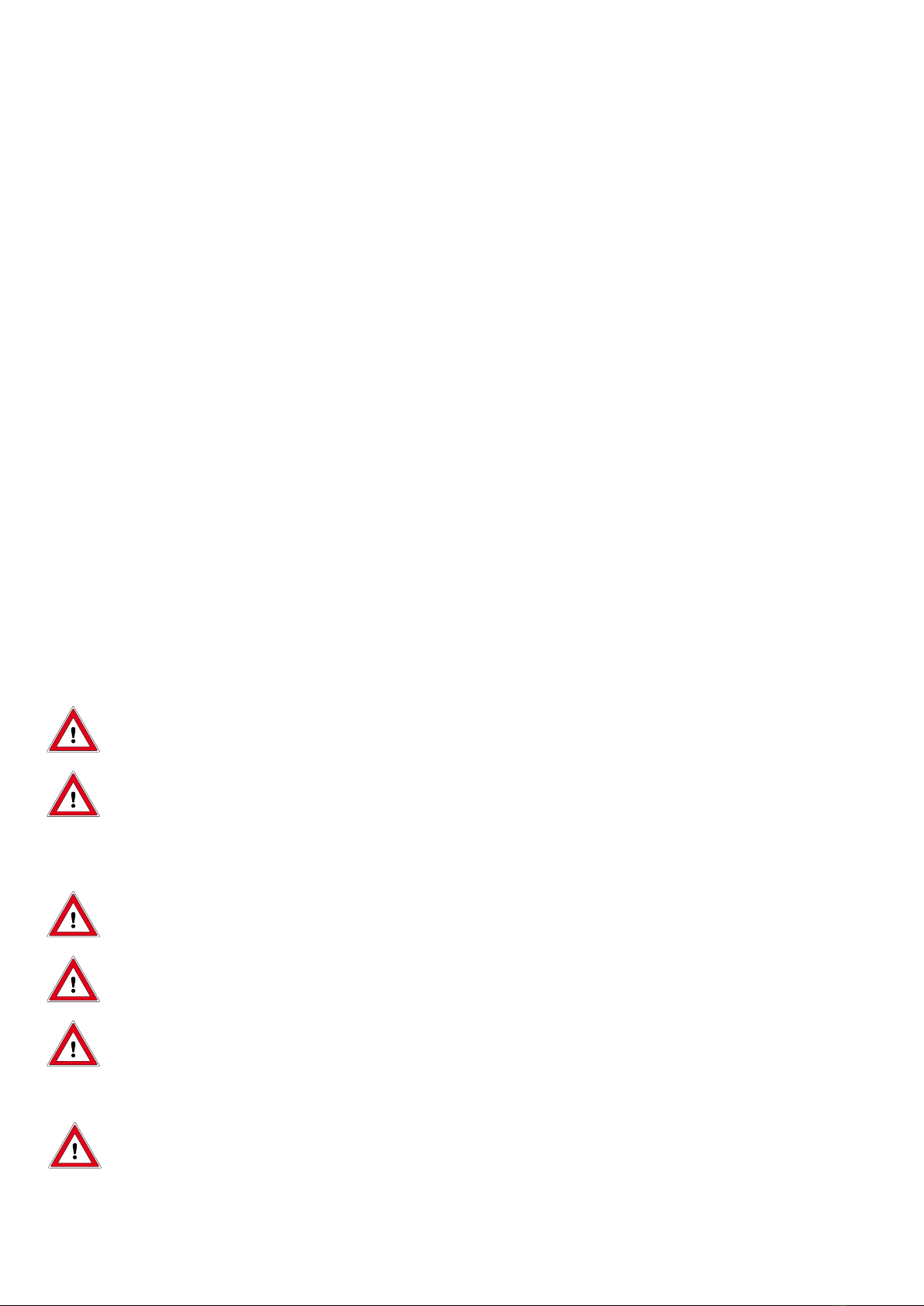
Your K8 / K12 / K20 / K16 / K24 / K40 digestion unit is
packed in three parts:
Heating block, ready assembled with mounting rail for
sample rack and exhaust collector
Sample rack
Exhaust collector, ready assembled, with glass grid
and mounting frame
Plus
1 set of sample vessels matching to the digestion unit
Exhauster hose for connection to a behrosog process
exhauster system, for example
Drip pan, to be installed under the exhaust collector.
Correct use of the device
The behrotest® K8 / K12 / K20 / K16 / K24 / K40 diges-
tion unit is used for heating of samples in the appropriate
digestion tubes. It is used, in particular, for quantitation of
total nitrogen using the Kjeldahl digestion method.
The digestion unit can be heated to 430 ° C. Always
ensure that you have selected the temperature program
appropriate to your samples. Use the digestion tubes
appropriate to this temperature, e.g. behrotest®diges-
tion tubes. Only use the appropriate type of digestion
tubes (round-bottom tubes).
Please under all circumstances note and adhere to the
following items, in order to ensure the greatest possible
operating safety and reliability and the longest possible
service-life for your digestion unit:
Always operate the appliance in accordance with
the instructions and data contained in this operating
manual!
Modifications to the appliance will result in forfeit of
any guarantee claims and can result in serious defici-
encies in the unit‘s operating safety and reliability.
During te Kjeldahl digestion, solfuric acid vapours
(and other aggressive gases) are set free. Always
operate the appliance with a scrubber system (e. g.
behrosog) and place the appliance and the scrubber
in a fume cupboard.
Never under any circumstances expose the dige-
stion unit to aggressive vapours, such as fumes from
acids, alkalis or solvents!
Always operate the behrotest® K8 / K12 / K20 / K16 /
K24 / K40 digestion unit under normal laboratory condi-
tions.

– 6 –
behrotest®K8 / K12 / K20 / K16 / K24 / K40
059111
1
2
3
1.31.4
1.5
1.6
1.7
1.8
3.5
3.3
3.4
2.2
2.3
2.4
2.1
1.1 - 1.2 →
3.1
3.2
2.5 - 2.9 →
1 Heating block :
1.1 Operating unit
1.2 Mains switch
1.3 Heating slots for sample vessels
1.4 Aeration slots
1.5 Mains plug
1.6 Mounting rail, with:
1.7 Hooks for suspending the sample rack while not
in use
1.8 Cut-outs for suspending the exhaust collector
while not in use
2 Sample rack
2.1 Handles
2.2 Upper guide roller; it also serves for suspending
the sample rack on the hooks 1.7
2.3 Lower guide roller
2.4 Sample vessels
Overview of the K8 / K12 / K20 / K16 / K24 / K40

– 7 –
behrotest®K8 / K12 / K20 / K16 / K24 / K40
059111
© behr Labor-Technik GmbH
1
2
3
1.11.2
2.5
←1.3 - 1.8
2.7
2.6
2.8
2.9
4
2.5 Front lid, removable
2.6 Fold for fastening the front lid on the frame of
the sample rack
2.7 Middle part of the frame, to hold the fold (2.6) of
the front lid
2.8 Hooks for fastening the front lid on the lower
frame bar of the sample rack
2.9 Lower bar of the frame, to hold the hooks (2.8)
of the front lid
3 Exhaust collector:
3.1 Handles
3.2 Gas outlet
3.3 Socket for suction hose
3.4 Suction hose
3.5 Hooks for suspending the exhaust collector in
the cut-outs 1.8 on the mounting rail
4 Drip pan

– 8 –
behrotest®K8 / K12 / K20 / K16 / K24 / K40
059111
Setting up
Position the heating block on the place provided in
the fume cupboard. It should be located to the left of
and adjacent to the exhauster system. Leave some
room to the left and right; the aeration slots must be
free.
Insert the sample vessels into the sample rack.
Position the sample rack on the heating block.
Connect the exhauster hose to the socket on the rear
panel of the exhaust collector.
For the moment suspend the exhaust collector in the
cut-outs on the top end of the mounting rail. Check
that it is securely engaged.
Connect the exhauster hose to your process
exhauster system.
Drip pan
After finishing a digestion, insert the drip pan below the
exhaust collector. Insert the drip pan on the rail under
the bottom of the exhaust collector and shift it in. Lift it
up a bit so the hook can engage on the front panel of
the exhaust collector. Don’t forget removing the drip pan
before starting the next digestion.

– 9 –
behrotest®K8 / K12 / K20 / K16 / K24 / K40
059111
© behr Labor-Technik GmbH
Handling
The behrotest®K8 / K12 / K20 / K16 / K24 / K40 makes
it quick and easy for you to insert your samples into the
heating block and to remove them for cooling down.
Thus you are always sure that all samples have been
treated exactly the same.
Why not get acquainted with the handling right now?
Parking the sample rack
On the middle of the mounting rail in the rear of the heat-
ing block you will see two hooks to hang the sample rack
on. When lifting the sample rack out of the heating block,
run it along the mounting rail, and it will engage in the
hooks automatically.
Grasp the sample rack using the two red handles.
Lift the rack carefully. Run it along the mounting rail
while doing so. Lift the rack upward until you hear it
engage.
Lower the rack carefully onto the hooks, in order to
check that it has engaged correctly. If this is not the
case, lower it again and repeat the above procedure.
Now the device is in the same position as before the
start of a digestion.
Insertig the samples into the heating block
Grasp the sample rack using the two red handles.
Position the sample rack on the digestion unit in such
a way that the sample vessels locate in the holes in
the digestion unit.
Take the exhaust collector from the top of the
mounting rail, and place it on top of the sample rack.
The upper parts of the PTFE stoppers will rest on the
rims of the sample vessels, and the suction tubes will
go into the sample vessels so the fume extractor can
remove any vapours coming out of them.

– 10 –
behrotest®K8 / K12 / K20 / K16 / K24 / K40
059111
Removing the samples from the heating block
When the digestion is completed, you should take the
samples out of the heating block but leave the exhaust
collector on the sample rack until the samples have
cooled down. So now you need to lift the sample rack
along with the exhaust collector out of the heating block
and park them.
Grasp the sample rack using the two red handles.
Lift the rack carefully, together with the exhaust col-
lector. Run it along the mounting rail while doing so.
Lift the rack upward until you hear it engage.
Lower the rack carefully onto the hooks, in order to
check that it has engaged correctly. If this is not the
case, lower it again and repeat the above procedure.
Parking the exhaust collector
Grasp the exhaust collector using the two red
handles.
Remove the exhaust collector from the sample rack
and suspend it in the cut-outs at the top end of the
mounting rail.
Front lid on the sample rack
Danger of burn! The front lid gets hot! o
not try to remove the front lid while a dige‑
stion is in progress.
The lid on the front side of the sample rack may be taken
off. Thus you have the samples in view while digestion is
in progress.
For routine digestions you should leave the front lid on.
With the front lid on, less heat will escape so you will
save energy.
Removing and remounting the front lid
Put the sample rack on an even surface.
For taking the lid off, hold the sample rack down and
pull the lid upwards until it can be taken off.
For putting the lid on, insert it in a way as for the
hooks and the fold to engage behind the lower and
middle part of the sample rack frame, as indicated.

– 11 –
behrotest®K8 / K12 / K20 / K16 / K24 / K40
059111
© behr Labor-Technik GmbH
behrotest
®
K 12
Press button for
Enter
–+
Prog 01/01 ==>>
022 °C
Switching the appliance on
Switch the mains switch on the front of the appliance to
the „I“ position.
The mains switch of the behrotest®K8 L / K12 L /
K20 L / K16 L / K24 L / K40 L performs two functions.
It is used, on the one hand, to switch the unit on and
off. There is, in addition, a fuse integrated into the
switch.
This fuse functions similarly to a miniature circuit-
breaker (m.c.b.) familiar from your household wiring
system. It interrupts the electrical circuit if an over-
current occurs.
Since it is necessary to pretension a spring for this
safety function, the mains switch on the digestor
requires greater force for switching on than a con-
ventional mains switch.
An initialization message will appear briefly on the
display when the unit is switched on. The main menu
appears once the initialization routine has been com-
pleted:
The device is now ready for operation.
Don‘t wonder if the start menu appears in German.
This is the factory setting; you‘ll soon see how to
change it (see p. 12 / 13).
Using the K8 / K12 / K20 / K16
/ K24 / K40
The operating unit
You can program and operate your behrotest® K8 / K12
/ K20 / K16 / K24 / K40 quite simply using a single but-
ton. The principle is the same in all cases:
The principle remains in all cases the same:
Turning the knob enables you to choose an option. The
currently addressable option is recognized by being
highlighted with light text on a dark background.
The knob may be turned in both directions. In doing this,
you will pass all possible options in the display shown
and will always again find the desired option on contin-
ued turning. Try this for yourself.
The desired option is implemented by pressing on the
knob.
The complete procedure of choosing by turning and
implementing by pressing will henceforth simply be
called „selecting.“
Operating unit

– 12 –
behrotest®K8 / K12 / K20 / K16 / K24 / K40
059111
Configuring the K8 / K12 / K20 / K16 /
K24 / K40 to meet your needs
You can, in fact, use your K8 / K12 / K20 / K16 / K24 /
K40 for analyses right now. You should, however, take a
couple of minutes to perform one or two settings.
These settings can, of course, also be made or modified
at a later time.
This screen will appear when the unit is switched on:
Prog 01/01 ==>>
022 °C
Turn the operating button until the ==>> menu item
is indicated and then press the button. The following
menu will appear:
GERAET
PROGRAMM
<<== zurück
01
Select the Geraet (Device) menu item.
You will then move to a menu consisting of two
pages.
Select the required entry by turning the operating but-
ton if you wish to change a setting. Press the button to
select the entry and set the required value by turning the
button. Store the value by pressing the operating button
again.
The Start menu
1 If a program has been started, or the unit is preheat-
ing, the target temperature is displayed here.
If no program is running, but a starting time has been
selected, the starting time is displayed here.
This box is otherwise blank.
2 The temperature currently measured by the tempera-
ture sensor is always displayed here.
3 „Start” menu item: The temperature program most
recently selected starts if this menu item is selected.
What program this is is1 indicated at bottom left.
4 „Preheat ON/OFF“ menu item: the K8 / K12 /
K20 will preheat to the starting temperature for the
temperature program selected if this menu item is
selected. The menu item will then change to „OFF“.
Select „OFF“ in order to switch the heating function
off again.
5 The program currently selected, and the program
step reached, are indicated here.
6 „Continue“ menu item: select this menu item to
access other possible settings. You can
- select another program
- write a new program
- configure the unit to your needs
Prog 01/01
14:05
==>>
022 °C
3
1
65
4
2

– 13 –
behrotest®K8 / K12 / K20 / K16 / K24 / K40
059111
© behr Labor-Technik GmbH
First page: Language and time
Select language
UHRZEIT
SPRACHE
<<== ==>>
D
11:20
Three languages are permanently programmed in the
K8 / K12 / K20 / K16 / K24 / K40 : D (German), GB (Eng-
lish), F (French). A fourth language can be added as an
option.
German is the default (ex-works) language. A different
language can be selected using this menu.
Select the Sprache (Language) menu item. The
entry for the language will now appear on a dark
background. Turn the operating button until the
required language appears, and then press the but-
ton.
From this point on, all menus and messages will appear
in the language you have selected.
Setting the time
You should also set the time while you are on this page.
The time is required to permit use of the K8 / K12 / K20‘s
Autostart function.
Select the Time menu item. The first digit of the
hours will then appear marked.
TIME
LANGUAGE
<<== ==>>
GB
11:20
You can now enter the digits for the time one after the
other. Turn the operating button until the correct digit
appears, and then press it.
If an illogical value is entered, such as „26“ for the
hours or „61“ for minutes, for example, the unit will
reject the value and instead jump back to the first
digit of the setting.
Use ==>> to move to the next page of this menu.
Second page: Autostart settings
START TIME
AUTOSTART
<<==
OFF
11:20
The Autostart settings can be selected on this page. You
can, for example, set the unit to preheat at a specified
time or to start a temperature program at a specified
time.
Autostart The following possibilities can be selected
here:
Off - the K8 / K12 / K20 / K16/ K24/ K40 will
only start to heat when a program is star-
ted or On is selected in the Start menu.
On - the K8/ K12/ K20/ K16/ K24/ K40 will
preheat to the starting temperature of the
most recently selected program as soon
as it is switched on at the mains switch
(p. 7, 2.3).
Prg - the K8/ K12/ K20/ K16/ K24/ K40 will
start the most recently selected tempera-
ture program at the Start time.
Tme - the K8 / K12/ K20/ K16/ K24/ K40
will start to preheat to the starting tempe-
rature of the most recently selected tem-
perature program at the Start time.
Start time Starting time for Prg and Tme.
The value can be set digit-by-digit, as
described before.
<<== back.
Selecting <<== repeatedly returns the unit to the Start
menu.

– 14 –
behrotest®K8 / K12 / K20 / K16 / K24 / K40
059111
Creating a temperature program
The K8 / K12 / K20 / K16 / K24 / K40 can be used to
write up to ten different temperature programs.
A program can have up to 10 program steps.
When writing a program, always note its purpose
and the settings selected.
Select ==>> in the Start menu and select Program
in the menu which then appears.
You are now on the first page of the Program menu.
PROG.NUMBER
<<== ==>>
01
Select the entry box for the Program No.
DEVICE
PROGRAM
<<==
01
Select the required Program No. You should select 01
if you have not yet written any other program.
Then select ==>>.
You will now see for every program step a page, on
which you can enter the settings for this step.
TIME
FUNCTION
TEMPERATURE
Program 01/05
<<== ==>>
350
120
T
The Program No. and the Program Step No. which you
are currently editing are shown in the top line.
Program 07/05, for example, indicates the fifth step in
Program No. 07.
This screen page will change its appearance depending
on the Function you select.
There are the following possibilities:
Function T: Temperature step
TIME
FUNCTION
TEMPERATURE
Program 01/05
<<== ==>>
350
120
T
In this function, the unit heats up to the specified
Temperature as quickly as possible (if it is not already
preheated) and then maintains this temperature. The
entire procedure (heating-up and maintaining, together)
lasts the stated Time in minutes.
You can enter Temperature and Time digit-by-
digit. The unit will not accept an impermissible tempera-
ture and will instead jump back to the first digit of the
entry box.

– 15 –
behrotest®K8 / K12 / K20 / K16 / K24 / K40
059111
© behr Labor-Technik GmbH
Function C/M: Heating rate
(degrees Celsius per Minute)
TIME
FUNCTION
TEMPERATURE
Program 02/07
<<== ==>>
350
120
C/M
In this function, the unit heats up uniformly to the speci-
fied Temperature (in degrees Celsius) in the specified
Time (in minutes). It thus operates on a temperature
gradient.
The temperature gradients which can in fact be
operated depend on the type and heat output of
the digester, and also on the heat capacity of the
samples.
Perform a trial run and find out for yourself, using
the temperature display, whether the temperature
plots set can actually be achieved.
Function E: End
This function is used to inform the K8 / K12 / K20 / K16 /
K24 / K40 that the temperature program ends here.
Every program memory slot consists of ten slots for pro-
gram steps. The K8 / K12 / K20 / K16 / K24 / K40 works
through these ten program steps in sequence if it does
not previously encounter an End step.
The last program step of every program must there-
fore be an End step. An End step is only not needed if
the program actually has the maximum of ten steps.
A program can thus be written as follows:
For the first step, enter the required function and the
corresponding values.
Select ==>>. This then leads to the next program
step.
Continue this procedure to program all the required
steps.
Select <<== if you wish to check or modify the pro-
gram step entered. Use ==>> to move forward again.
Remember to enter End (Function E) as the final
step. An End step is only not needed if the program
has ten steps.
Press <<== repeatedly to return to the Start menu.
Which program settings are most useful for you will
depend on your digester, the digestion method and
the nature of the samples.

– 16 –
behrotest®K8 / K12 / K20 / K16 / K24 / K40
059111
Processing samples
Switch the K8 / K12 / K20 / K16 / K24 / K40 on (mains
switch on the rear panel of the unit, Page 7, 2.3).
Prog 01/01
14:05
==>>
022 °C
If you have selected Prg or Tme for the Autostart func-
tions, the starting time will be shown at the top left; the
target temperature will be shown in this position if the
unit is preheating.
Select program
The most recently selected program is displayed in the
bottom line of the Start menu. Select a different program
if this is not the program you require now:
Select continue ==>>
DEVICE
PROGRAM
<<==
01
Select Program
and on the next page Program No.
PROG.NUMBER
<<== ==>>
01
Select the required Program No.
Return to the Start menu by selecting <<==
repeatedly.
Preheating the digester
Danger of burns! The inner zone of the
heating block gets hot!
Never touch the hot glasses or the area
of the heating block around the mounting
holes with the bare hands.
If necessary, preheat the digester to the starting
temperature.
Prog 01/01 ==>>
022 °C
Select the ON menu item in the Start menu.
The device will now start to preheat to the starting
temperature of the program selected.
Prog 01/01 ==>>
022 °C
The temperature to which the device will preheat is now
shown at the top left of the display, and the temperature
reached at the center.
Select OFF if you wish to abort preheating.
Inserting the samples,starting the program
Danger of burns! The inner zone of the
heating block gets hot!
Never touch the hot glasses or the area
of the heating block around the mounting
holes with the bare hands. Use the sample
rack to insert the samples.
Hook

– 17 –
behrotest®K8 / K12 / K20 / K16 / K24 / K40
059111
© behr Labor-Technik GmbH
If the drip pan has been inserted, take it out. To do
this, lift the front side of the drip pan up a bit so you
can pull the hook over the panel of the exhaust
collector.
Position the sample rack bearing the samples on the
digestion unit in such a way that the sample vessels
locate in the holes in the digestion unit.
Put the exhaust collector in position and switch the
exhauster system on.
Select the Start menu item in the Start menu.
Prog 01/01 ==>>
°C
154
The selected target temperature will now appear at top
left on the display, with the currently measured tempera-
ture next to it;
The time for this program step and total remaining time
are shown in the next line down.
The program step which is currently being run is shown
at the bottom.
Prog 01/02
154 °C
min
120 79
The K8 / K12 / K20 / K16 / K24 / K40 does not react
to any operation of the operating button while a pro-
gram is running. The program cannot be interrupted
by actuating the operating button. This is intended to
prevent any inadvertent interruption or manipulation
of a program while it is running.
Please use the mains switch (Page 7, 2.3) at the
bottom on the front side if you should need to abort a
digestion.
A signal is heard, and the heating system switches off,
when the program has been completed.
Finishing digestion and taking out the samples
Danger of burns! The inner zone of the
heating block and the sample vessels get
hot!
Never touch the hot glasses or the area
of the heating block around the mounting
holes with the bare hands. Always remove
the samples from the heating block using
the sample rack and allow them to cool as
described here.
Caution the heating block and the tubes
get 400 °C hot. If the sample vessels are
left in the heating block cooling down, they
may get jammed or even cracked due to
the different expansion coefficients.
Do not leave the sample vessels in
the block after digestion; proceed as
described here.
Hooks on which the sample rack can be suspended
are located on the mounting rail on the rear side of the
digestion unit. The rack will engage automatically in the
hooks if it is run along the rail during raising.
Grasp the sample rack using the two red handles.
Lift the rack carefully, together with the exhaust col-
lector. Run it along the mounting rail while doing so.
Lift the rack upward until you hear it engage.
Lower the rack carefully onto the hooks, in order to
check that it has engaged correctly. If this is not the
case, lower it again and repeat the above procedure.
Leave the exhaust collector on the sample rack until
the samples have cooled down.
Once the samples have cooled, switch the exhauster
system off.
Remove the exhaust collector from the sample rack
and suspend it in the cut-outs at the top end of the
mounting rail.
Insert the drip pan on the rail under the bottom of the
exhaust collector and shift it in. Lift it up a bit so the
hook can engage on the front panel of the exhaust
collector. Don’t forget removing the drip pan before
starting the next digestion.
The sample rack can now be removed for further
processing of the samples.
Hook

– 18 –
behrotest®K8 / K12 / K20 / K16 / K24 / K40
059111
Maintenance of your
K8 / K12 / K20 / K16 / K24 / K40
Danger of electric shock!
Always ensure that no liquids can come
into contact with cable connections or the
interior of the unit.
Never attempt to open the unit! Repairs
to electrical equipment may be performed
only by specialist electricians.
Checking the Temperature
All behr Kjeldahl heating blocks have a boring (2 mm ø)
in the center of the aluminium block. You can insert the
temperature sensor of an electronic thermometer there
to check the temperatur. Check if the temperature mea-
sured corresponds to the temperature display of the
heating block.
Remove the temperature sensor again before starting a
digestion.
Cleaning the Exhaust Collector
Danger of injury in case of breakage of
glass! Always adhere to your professional
association's regulations when handling
glass elements!
Caution: there may be sulphuric acid in
the exhaust collector! It might burn you.
Adhere to the current Hazardous Sub‑
stances Ordinance!
If, during a digestion, the exhaust collector has been
contaminated by sample components, you can easily
clean it.
Cautiously lay the exhaust collector upside down,
with the nozzles pointing upwards.
Rinse the nozzles with distilled water.
If need be, gently apply a small bottle brush or a pipe-
cleaner to clean the nozzles.
If necessary, you can dismantle the PTFE sealings from
the nozzles for cleaning.
Grasp the sealing at the sides, and at the same time
cautiously press against the nozzle with your thumbs.
Gently wiggling withdraw the sealing from the nozzle.
After cleaning the sealings, put them on the nozzles
again by reversing this procedure.

– 19 –
behrotest®K8 / K12 / K20 / K16 / K24 / K40
059111
© behr Labor-Technik GmbH
Changing Tubes of the Exhaust
Collector
If a glass part of the exhaust collector has broken, you
need not replace the exhaust collector as a whole. The
iner parts of the exhaust collector consist of
the suction vessels that reach into the sample ves-
sels with their long tubes (carrying the PTFEstoppers
on their ends); with
short Viton tube cuttings they are connected to the
collecting tube. And on the nozzle of this collecting
tube there is the
suction hose that connects the exhaust collector to
the scrubber.
Danger of injury in case of breakage of
glass! Always adhere to your professional
association's regulations when handling
glass parts!
Opening the Housing of the Exhaust Collector
Undo the four screws on the rear panel of the
housing.
Undo the four screws on the roof of the housing.
Take the panel off that forms the rear and the roof of
the housing.
On top of the suction vessels you see the two crossbars
that are fixing them. They had held the roof panel by
the four screws that you have just unscrewed. They are
themselves fastened to the intermediate bottom by four
long screws.
Unscrew the long screws that hold the crossbars to
the intermediate bottom.
Take these two crossbars off the suction vessels.
The suction vessels, with their long suction nozzles, go
through borings of an intermediate bottom. In order to
take them out you must first take the PTFE stoppers off
the suction nozzles.

– 20 –
behrotest®K8 / K12 / K20 / K16 / K24 / K40
059111
Taking Off the PTFE Stoppers
Cautiously turn the exhaust collector bottom up so
that the suction nozzles are pointing upwards.
From the suction vessels you want to replace, pull the
PTFE stoppers off.
Turn the exhaust collector to the normal position
again.
Changing the Glassware
On the suction vessel you want to replace, pry the
upper hose clip open with broad pliers and push the
hose clip downwards on the hose.
Cautiously pull the suction vessel out of the viton
hose cutting.
In case you want to replace the collecting tube, you
need to take out all the suction vessels this way.
Insert the new suction vessel into the intermediate
bottom and push the nozzle into the viton hose cut-
ting.
Secure the joint of the hose cutting and the new
suction vessel by pushing the hose clip to the upper
position again.
If need be, shift the collecting tube and the suction
vessels connected to it in such a way that the nozzles
go centered through the borings of the intermediate
bottom.
Lay the crossbars on top of the suction vessels again
and screw them to the intermediate bottom with the
long screws.
Screw the roof panel onto the crossbars again.
Screw the back panel tight too.
Turn the exhaust collector bottom up again and push
the PTFE stoppers on the nozzles.
This manual suits for next models
5
Table of contents
Other BEHR Laboratory Equipment manuals
Popular Laboratory Equipment manuals by other brands

ROBOfiber
ROBOfiber INJ-GE-30R user manual

Tuttnauer
Tuttnauer Valueklave 2540 Technician manual

Stuart
Stuart SBH CONC/1 Instructions for use

Ocean Insight
Ocean Insight FLAME Installation and operation manual

Brunswick
Brunswick BIOFLO 3000 manual

Malvern Instruments
Malvern Instruments Zetasizer Nano Accessories guide

Shimadzu
Shimadzu Nexera CL Series System guide

CSZ
CSZ ZP Series Installation, operation & maintenance manual

Agilent Technologies
Agilent Technologies G2916A manual

Ametek
Ametek Motec MBE5201-1 Installation and operating instructions

Acea
Acea NovoCyte Maintenance Guide

Thermo Scientific
Thermo Scientific 1300 Series operating manual