HEKA EPC 9 User manual

8.52
EPC 9 Manual
HEKA Elektronik Dr. Schulze GmbH
Wiesenstraße 71 • D-67466 Lambrecht • Germany
Tel: +49 (0) 6325 9553 0 • Fax: +49 (0) 6325 9553 50
Web Site:
http://www.heka.com
E-mail:
•

Table of Contents EPC9 Manual 2
Table of Contents
1. Introduction 5
Introducing the EPC 9 _____________________________________________ 5
References ____________________________________________________ 6
Naming Conventions______________________________________________ 8
EPC 9, EPC 9 Double, and EPC 9 Triple...................................................................................8
Windows versions ................................................................................................................8
Support Hotline _________________________________________________ 9
2. Description of the Hardware 10
Probe _______________________________________________________ 10
Main Unit_____________________________________________________ 11
EPC 9 Double and Triple __________________________________________ 15
3. Installation 16
Installation Procedure ____________________________________________ 16
Calibrating the EPC 9 ____________________________________________ 16
Creating the C-fast Lookup Table_____________________________________ 18
4. Verifying and Testing the EPC 9 19
Testing the EPC9 with the Model Circuit ________________________________ 19
The Model Circuit MC 9.......................................................................................................19
Step 1: Applying the Test Pulse.............................................................................................20
Step 2: ”On-Cell” Voltage-Clamp Recording.............................................................................23
Step 3: ”Whole-Cell” Voltage-Clamp Recording ........................................................................24
Step 4: ”Whole-Cell” Current-Clamp Recording.........................................................................26
Step 5: Measuring the Noise of the Amplifier............................................................................29
Making a ”Full Test” _____________________________________________ 31
Measuring the Frequency Response __________________________________ 34

Table of Contents EPC9 Manual 3
5. E9SCREEN Software 35
EPC9 Window _________________________________________________ 35
Main Controls....................................................................................................................35
Hidden Controls.................................................................................................................46
Notebook Window_______________________________________________ 48
Drop-Down Menus ______________________________________________ 48
File Menu .........................................................................................................................48
Edit Menu.........................................................................................................................49
EPC9 Menu ......................................................................................................................50
Notebook Menu .................................................................................................................52
Calibrate Menu ..................................................................................................................53
6. Operating Modes 54
Voltage-Clamp Mode _____________________________________________ 54
Current-Clamp Mode _____________________________________________ 54
Test Mode ____________________________________________________ 57
Search Mode __________________________________________________ 58
7. Compensation Procedures 59
Series Resistance Compensation ____________________________________ 59
Capacitance Compensation ________________________________________ 62
Offset Compensation_____________________________________________ 63
8. Patch-Clamp Setup 67
Mounting the Probe ............................................................................................................67
Ground Wires....................................................................................................................67
Grounding the Microscope ...................................................................................................67
External Shielding ..............................................................................................................68
Connections to other Instruments ..........................................................................................68
Pipette Holder and Electrode ................................................................................................ 68
Bath Electrode...................................................................................................................69
9. Patch-Pipettes 71
Glass Capillaries................................................................................................................71
Pulling..............................................................................................................................72

Table of Contents EPC9 Manual 4
Coating ............................................................................................................................72
Heat Polishing ...................................................................................................................73
Use of Pipettes .................................................................................................................. 73
10. Using the Patch Clamp 75
Forming a Seal_________________________________________________ 75
Initial Setup.......................................................................................................................75
Entering the Bath ...............................................................................................................75
Forming a Gigaseal ............................................................................................................76
Cell-Attached Recording __________________________________________ 76
Whole-Cell Recording ____________________________________________ 77
Breaking the Patch ............................................................................................................. 77
Capacitive Transient Cancellation..........................................................................................78
Series Resistance Compensation .......................................................................................... 78
Current-Clamp Recording__________________________________________ 79
11. Low-Noise Recording 80
Appendix I: Controlling E9SCREEN 83
Communication between E9Screen and other Programs _____________________ 83
Reserving the AD/DA-board for exclusive use .......................................................................... 83
The “EPC9out.EPC” file.......................................................................................................83
Controlling the EPC9 from another Program _____________________________ 85
Sending Commands to E9Screen..........................................................................................85
Error Messages..................................................................................................................87
Implemented Commands and Messages................................................................................. 87
Notes to Programmers.........................................................................................................91
Sample program ................................................................................................................93
Appendix II: Technical Data 98
Digital I/O Connector_____________________________________________ 98
Standard EPC9..................................................................................................................98
EPC9 Double and Triple ...................................................................................................... 99
Index 101

Introduction EPC9 Manual 5
1. Introduction
The patch-clamp technique was introduced by
Neher and Sakmann (1976) for recording the
currents in a small patch of membrane under
voltage-clamp conditions. In the intervening
years a number of changes have occurred, most
notably the development of the “gigaseal” by E.
Neher (1981). Various recording configurations
allow intracellular recordings to be made with
the same type of recording setup as used for
patch recording from the cell surface or cell-free
membrane patches (Hamill et al., 1981).
Introducing the EPC 9
The EPC9 represents roughly the ninth in the
series of patch-clamp designs in use in the
Göttingen laboratories. It is a logical successor to
the EPC7, retaining all of its features but adding
a number of capabilities, the most important
being implementation of full digital control of
the various functions. Thus, the new digitally
controlled EPC9 patch-clamp amplifier has no knobs, switches or dials. The Pulse
software replaces the analog controls of conventional amplifiers by using Macintosh
computers and a built-in ITC-16 interface. The convenient graphics display and
mouse operations provide unsurpassed versatility and ease of operation.
In addition to the controls for the amplifier and the built-in filters, the Pulse software
contains a powerful data acquisition system (sampling and storage in pulse, ramp
and continuous modes), a fully programmable pulse generator, and a digital
oscilloscope. Thus, the EPC9 offers all the features of a complete workstation for
controlling experiments and acquiring data. Furthermore, there is the PulseFit
software package as well as TAC (Threshold Analysis for single Channels) available,
which allow data analysis, data export, and graphics output.
The EPC9 also accepts a stimulus input and provides current monitor outputs just
like conventional amplifiers to operate in combination with a host computer running
custom and commercial software from other sources. The versatility of the EPC9 can

Introduction EPC9 Manual 6
best be appreciated by the variety of experiments that can be carried out with it.
Besides high-resolution recordings of single channels, it can be used in studies of
whole-cell voltage and current clamp, exocytosis (by monitoring changes in cell
membrane capacitance), and recordings from artificial membranes or loose-patch
experiments. Technically, the EPC9 is noteworthy for three special features, the
range-changing capability of the head stage, the extremely wide bandwidth available
from the current monitor circuitry, and the integrated transient cancellation
(automatically if desired) and series-resistance compensation functions. Together
these features mean that a single head stage suffices for both single-channel and
whole-cell recordings, and that both kinds of recordings can be made with high time
resolution and low noise.
This manual is designed to provide a general guide for setting up and using the
EPC9 for experiments. It covers general information about the hardware, the
E9Screen program, and basic principles o f the EPC9's functions and patch-clamp
techniques.
It is assumed that the reader has some familiarity with patch-clamp techniques;
should you be a newcomer to the field perhaps the best place to start would be the
paper by Hamill et al., where the basic gigaseal techniques are described and the first
three chapters of Single Channel Recording (B. Sakmann & E. Neher, eds., Plenum
Press, New York, 1995). Certainly, it will be worthwhile to read this manual
carefully. Many users will want to read some of the more advanced and complete
discussions of individual topics which can be be found in original articles and in the
books Single Channel Recording (B. Sakmann & E. Neher, eds., Plenum Press, New
York, 1995) and Methods in Enzymology, vol. 207 (Academic Press, New York, 1992).
References
Original Articles
Hamill, O. P., Marty, A., Neher, E., Sakmann, B. & Sigworth, F. J. (1981) Improved
patch clamp techniques for high-resolution current recording from cells and cell-free
membrane patches. Pflügers Arch. 391, 85-100.
Neher, E. (1981) Unit conductance studies in biological membranes. In: Techniques in
Cellular Physiology (P. F. Baker, ed.) Elsevier/North Holland.
Neher, E. & Sakmann, B. (1976) Single-channel currents recorded from membrane of
denervated frog muscle fibres. Nature 260, 779-802.

Introduction EPC9 Manual 7
Rae, J. & Levis, R. (1984) Patch clamp recordings from the epithelium of the lens obtained
using glasses selected for low noise and improved sealing properties. Biophys. J. 45, 144-
146.
Barry, P. H. & Lynch, J. W. (1991) Liquid junction potentials and small cell effects in
patch-clamp analysis. J. Memb. Biol. 121, 101-117.
Sigworth, F. J., Affolter, H. & Neher, E. (1995) Design of the EPC-9, a computer-
controlled patch-clamp amplifier. 2. Software. J. Neurosci. Methods 56, 203-221.
Book Chapters
Penner, R. (1995) Chapter 1: A practical guide to patch clamping. In: Single-Channel
Recording (B. Sakmann & E. Neher, eds.) Plenum Press, New York.
Marty, A. & Neher, E. (1995) Chapter 2: Tight-seal whole-cell recording. In: Single-
Channel Recording (B. Sakmann & E. Neher, eds.) Plenum Press, New York.
Heinemann, S. H. (1995) Chapter 3: Guide to data acquisition and analysis. In: Single-
Channel Recording (B. Sakmann & E. Neher, eds.) Plenum Press, New York.
Sigworth, F. J. (1995) Chapter 4: Electronic design of the patch clamp. In: Single Channel-
Recording (B. Sakmann & E. Neher, eds.) Plenum Press, New York.
Neher, E. (1995) Chapter 6: Voltage offsets in patch-clamp experiments. In: Single
Channel-Recording (B. Sakmann & E. Neher, eds.) Plenum Press, New York.
Colquhoun, D. & Sigworth, F. J. (1995) Chapter 19: Fitting and statistical analysis of
single-channel records. In: Single-Channel Recording (B. Sakmann & E. Neher, eds.)
Plenum Press, New York.
Neher, E. (1992) Correction for liquid junction potentials in patch clamp experiments. In:
Methods in Enzymology 207, 123-131, Academic Press, New York.

Introduction EPC9 Manual 8
Naming Conventions
EPC 9, EPC 9 Double, and EPC 9 Triple
Throughout the present manual we will address all three amplifier types as “EPC9”.
We will explicitly mention the particular amplifiers, where it is required.
Windows versions
The EPC9 is supported on Windows 3.1, Windows 95, Windows 98,
Windows NT 3.51, Windows NT 4.0, and Windows 2000.
Throughout the present manual we will address all the above Windows versions as
“Windows”. We will explicitly mention the particular Windows versions, whenever
it is required.

Introduction EPC9 Manual 9
Support Hotline
If you have any question, suggestion, or improvement, please contact HEKA’s
support team. The best way is to send us an e-mail or fax specifying:
•Your postal and e-mail address (or fax number)
•The program name:
E9SCREEN, PULSE, PULSEFIT, etc.
•The program version number:
v8.31, v8.50
•Your operating system and its version:
MacOS 7.6.1, MacOS 8.5,
Windows 98, Windows NT 4.0, etc.
•Your type of computer:
Mac PPC 8500, Pentium II 300 MHz, etc.
•Your acquisition hardware, if applicable:
EPC9, ITC–16, ITC–18
•Your amplifier, if applicable:
EPC9, EPC9 Double, Axon 200B, etc.
•The serial number and version of your EPC9, if applicable:
EPC9 single, version “920552 D”.
•The questions, problems, or suggestions you have
•Under which conditions and how often the problem occurs
We will address the problem as soon as possible.
HEKA Elektronik GmbH phone: +49 (0) 6325 9553 0
Wiesenstrasse 71 fax: +49 (0) 6325 9553 50
D-67466 Lambrecht/Pfalz e-mail:
Germany web:
http://www.heka.com
Description of the Hardware EPC9 Manual 10
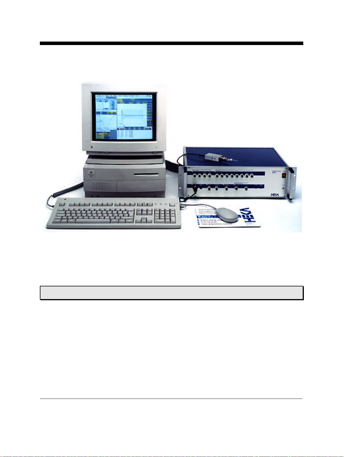
2. Description of the Hardware
The hardware components of the EPC9 patch-clamp system consist of the head stage
(or probe), the amplifier main unit with the integrated ITC-16 interface board, and
the computer system. Specific information about the hardware installation is given
below in Chapter 3. Installation on page 16.
Probe
The probe, or “head stage” of the EPC9 is contained in a small enclosure designed to
be mounted on a micromanipulator and directly attached to the recording
micropipette. It contains the sensitive amplifier that constitutes the current-to-
voltage converter, as well as components for injecting test signals into that amplifier.
On the probe are the following connectors:
Input Connector: This is a Teflon-insulated BNC connector. The standard pipette
holder plugs directly into this connector; the center pin is the amplifier input, and
the shield is driven with the command potential Vp.

Description of the Hardware EPC9 Manual 11
Note: Avoid touching the probe's input terminal, since the input circuitry of the probe can
be damaged by static electricity. When it is necessary to touch the input (e.g., while
inserting a pipette into the holder), ground yourself first by touching a grounded
metal surface.
Ref Output: The red 0.04" pin jack carries the command potential Vp.
Note: The metal case of the probe is also connected to this signal, and therefore must be
insulated from ground.
Gnd Connector: The black pin jack carries a high quality ground signal which is
useful for grounding the bath electrode and nearby shields without potential errors
that could arise from ground loops. This ground is connected directly to the signal
ground on the controller through the probe's cable. More details on grounding
practices will be provided in Chapter 8. Patch-Clamp Setup on page 67.
Main Unit
The main unit of the EPC9 contains the power supply, the signal processing
electronics, the AD and DA converters and the connectors for analog and digital
input/output. Essentially all of the calibration adjustments are made by digital
switches in the main unit, including those which depend on the properties of
components in the probe. The calibration parameters are preset by the manufacturer
and contained in the software package as the files “Scale.epc” and “CFast.epc”.
Unlike conventional amplifiers, hardware calibration of the EPC9 can also be
performed by the user if necessary (see section Calibrating the EPC 9 on page 16).
Note: Calibration parameters are unique to each amplifier and head stage combination.
Thus, if you exchange the head stage, be sure to perform a new hardware calibration.
Voltage Switch: A switch on the rear panel of the main unit selects between the 110
and 220 volt operation. Make sure that the switch is in the proper position and that
the correct fuse is installed.
Power Switch: In order to be initialized properly, the EPC9 must be switched on
before starting the software program that drives it, e.g., E9Screen or Pulse. These
programs however allow you to re-initialize the amplifier in case you forgot to turn
it on first.
Note: Since the calibration settings of the amplifier have been determined for a warmed-up
amplifier, switch on the amplifier ~15 min before starting an experiment. This will
ensure that the amplifier has warmed up to regular working temperature and
calibration parameters are most accurate.

Description of the Hardware EPC9 Manual 12
Chassis Gnd: The chassis is connected to the ground line of the power cord, as is
typical of most instruments. The Signal Ground is kept separate from the chassis to
avoid ground loops, but is connected to it through a 10 Ωresistor.
Test Input: This input is used for the Test mode. An external stimulus fed into the
Test Input is converted into a current (scaling is fixed at approximately -100 pA/V)
and injected as a test signal into the probe input. The current injection circuitry has a
very wide bandwidth (1 Hz to 1 MHz), allowing very precise determination of the
frequency response of the current monitor circuitry. With the Gain set to 10 mV/pA,
any signal applied to the Test Input connector will be reproduced with approximately
the same amplitude (but inverted) at the Current Monitor outputs.
Note: You can use the internal stimulator to generate a test pulse for determining the
accuracy of the calibration parameters. Simply connect the “Test Output” (DA 2)
with the “Test Input” and stimulate with the desired voltage pulse.
External Stim. Input: Signals from an external stimulus source are applied here;
they can be summed with the internal stimulus if desired. The combined stimulus
signal is passed through a 2-pole filter to round off stepwise changes in voltage. This
avoids nonlinearities (from slew-limiting amplifiers) in the command processing
circuitry and also reduces the amplitude of the current transients from rapid
charging of the pipette. Two degrees of filtering, specified as the risetimes (time from
10% to 90% of the amplitude of a step change) are available in the software: 2 µs,
which is the minimum required to avoid nonlinearities in the internal circuitry, and
20 µs, which is preferable for all but the fastest measurements, to reduce the
capacitive transients.
Voltage Monitor: This output signal provides a monitor of the pipette potential. It is
scaled up by a factor of 10 relative to the potential applied to the pipette. The output
impedance is 50 Ω. The unscaled signal may be viewed on the software oscilloscope.
Current Monitor: The output signals are filtered according to the settings in the
software. Positive voltages correspond to currents flowing out of the pipette.
Typically, the left-hand output (Filter 1) is fed to a data recorder (e.g., tape recorder,
PCM/VCR combination, or DAT recorder) to record the signal at wide bandwidth,
while the additionally-filtered signal from the right-hand output (Filter 2) is applied
to an oscilloscope for monitoring the progress of the experiment. Either signal may
be viewed on the software oscilloscope.
Probe: This input accepts the multi-pin connector of the head stage.
Signal GND: This banana jack is a high-quality signal ground connection that can be
used to ground other parts of the experimental setup as necessary (see Chapter 8.
Patch-Clamp Setup on page 67).

Description of the Hardware EPC9 Manual 13
Clipping: This LED lights whenever an amplifier saturates in the current monitor
pathway. The indicator is important in voltage-clamp experiments where capacitive
artifacts will be subtracted in a computer; the subtraction will work well only as long
as no saturation occurs, and this indicator serves as a simple monitor of this
condition. It is particularly useful since it will indicate clipping by internal amplifiers
even in cases where, because of filtering, the output voltage is not saturated.
Digital Bus: This LED lights whenever digital information is sent from the computer
to the EPC9 amplifier.
AD Inputs: The built-in laboratory interface (ITC-16) provides eight AD channels (0-
7). AD channels 6 and 7 are internally connected to the EPC9 and are used by the
software supplied. Channel 6 is labeled “I-Mon” and carries the Current Monitor 2
output. Channel 7 carries the output of the EPC9's internal multiplexer, which in
most operating modes is set to the voltage monitor signal. You normally should not
connect anything to channel 6 and 7, unless you wish to inspect the signals for
diagnostic reasons. However, channels 0-5 are freely available for application
programs. For example, the Pulse program can use these channels to monitor
temperature, pressure or outputs from other sensors.
DA Outputs: Four DA channels are provided (0-3). They carry the following signals:
• DA-0 - Free (C-slow during Cap. Track)
• DA-1 - Free (G-series during Cap. Track)
• DA-2 - Test output (used in self-test and calibration)
• DA-3 - Internal stimulus output (used to monitor the stimulus)
Note: These are output connectors! Make sure that you never feed stimuli into these
outputs.
DA-1 is typically used to trigger an oscilloscope or an isolation unit. In the
Capacitance-Tracking mode of E9Screen, DA channels 0 and 1 can be used to provide
optional special-purpose outputs. DA-2 can be used to inject test signals into the
EPC9 circuitry in the Test mode (see Chapter Measuring the Frequency Response on
page 34). DA-3 is wired internally as the internal stimulus generator.
The specific DA-channel assignments are made in the software (see Pulse Manual,
Chapter 6 - EPC9 Amplifier). DA channel 2 (Test) should normally not be used. Also,
DA-3 should normally not be used to monitor the stimulus output, because this may
degrade the noise performance of the EPC9. The buffered Voltage Monitor output
should be used instead. The voltage at the connector is 10 times the nominal
stimulus amplitude.

Description of the Hardware EPC9 Manual 14
Rear-panel connectors: Three 40-pin connectors and an analog trigger input allow
connection of the EPC9 to other devices:
•Computer-Interface: This is the connection to the Mac-23, AT-16, PCI-16, or
PCI-18 board in the host computer, that allows the computer to communicate
with the EPC9.
•Digital I/O: TTL-level, digital input and output lines are available here for the
control and monitoring of digital signals. See pin assignments in Appendix II:
Technical Data.
•VR10/100: This digital input port is provided by the ITC-16 but is not used by
the EPC9 and its software.
•Trigger In: Input for an external trigger to start data acquisition when the ITC-
16 is waiting for an external trigger. This mode is set in Pulse+PulseFit when
either Trigger Series or Trigger Sweeps is selected in the Pulse Generator.

Description of the Hardware EPC9 Manual 15
EPC 9 Double and Triple
The EPC9 Double and Triple contain two and three independent EPC9-amplifiers in
one case, respectively. All amplifiers share a single ITC-16 AD/DA-board.
The ITC-16 board provides 4 DA-channels which are sufficient to allow
simultaneous stimulation of every individual amplifier. The 8 available AD-channels
can independently read all voltage- and current-outputs of the individual amplifiers.
One amplifier is always selected as the "active" amplifier. The "active" amplifier is the
one which is enabled to receive configuration commands. One can visually identify
the "active" amplifier by checking the DIGITAL BUS light. The green LED-light of
the "active" amplifier flickers when the digital lines are alive during command
transmission. The notion "active amplifier" does not imply that the other amplifiers
are not active. They remain fully functional, but not enabled to receive programming
commands.
Note 1: Mux-AD, Test-DA, and Clipping-lines are connected to the selected "active" EPC9
board only. Stim-DA, Vmon-AD, and Imon2-AD are always accessible for all
individual EPC9 boards.
Note 2: The Test-DA can be connected to the stimulus input of all 3 amplifiers. This allows
to simultaneously stimulate all 3 amplifiers. Separate scaling factors are available for
each individual amplifier.
The internal, hardwired DA- and AD-channel assignments for the EPC9 Double and
Triple are as follows:
EPC9 amplifier board
123
Stim-DA 0 1 2
Vmon-AD 0 2 4
Imon2-AD 1 3 5
Test-DA 1,2 333
Mux-AD 1777

Installation EPC9 Installation 16
3. Installation
Installation Procedure
Please, installation procedure for the EPC9 and the required software is described in the
separate “Installation_8x5”manual.
Calibrating the EPC 9
If you wish to calibrate your amplifier proceed as stated in this section. Calibration is
usually not necessary with a new amplifier, since you can use the calibration files
supplied by HEKA. However, it is advisable to recalibrate the EPC9 twice a year or
whenever the frequency response of the amplifier is not accurate or offset currents
become noticeable.
Note: The calibration file contains the settings of the digital switches and controls of the
amplifier. These are unique to a given combination of amplifier and headstage (probe)
and cannot be used for another EPC9. Therefore, you have to recalibrate the amplifier,
when you replace the probe! This is a big advantage of the EPC9, since you can use any
probe with any amplifier and replace a broken probe without having to send the amplifier
in for recalibration.
Before starting the calibration make sure that the
amplifier has reached its operational temperature,
since the calibration depends on temperature. We
advice to let the EPC9 warm up for 60 minutes
after powering the amplifier on. Start the
E9SCREEN program. The default installation
copies it into the E9Scren folder inside the HEKA
folder. Windows users might alternatively use the
Start button to launch E9SCREEN from Programs
HEKA. In the program, go to the Calibrate
menu. This menu contains all the items involved in
calibration generation of scale files. If there is no
valid calibration, the menu item Make CFast will
be disabled. If you have an EPC9 Double or Triple
this menu item will also be disabled, unless each amplifier has been calibrated correctly.
To perform the calibration select Calibrate from the Calibrate menu. E9SCREEN will
warn you that this procedure may take up to 10 minutes, depending on the speed of
your computer (6 minutes on a 300 MHz PII system). Go ahead by clicking the Yes
button.

Installation EPC9 Installation 17
Then you are instructed to remove anything from the probe and shield its input:
You can use the metallic cap that came with your EPC9 and put it on the BNC connector
of the probe to shield it. Please make sure that really nothing except the metallic cap is
connected to the probe (the red and the black pin jack should be free) and that no BNC
cables are connected to the inputs and outputs of the EPC9 !
At the end of the calibration, E9SCREEN will let you know, whether the calibration
succeeded or failed. If it succeeded, the program will ask you, whether you want to save
the new calibration file and generates the proper name for the calibration file.
It is not advicable to save the file under a different name, because in that case you would
have to manually load the scale file during every initialization.
Note: It is very advisable to store the calibration files only in the one place. The best place to
put the calibration files is the E9Screen folder. Most users will run more than one
program which needs the calibration files to properly control the EPC9, e.g. PULSE and
E9SCREEN. Both programs will load by default the calibration files from the E9Screen
folder. If the calibration files are in multiple places the programs may load different
calibration files with possibly unpleasant consequences!
Finally, E9SCREEN re-initializes the amplifier.

Installation EPC9 Installation 18
If you have an EPC9 Double or Triple, you
should proceed to calibrate the second and
third amplifier as well. From the amplifier
pop-up menu, choose 2. Amplifier or 3.
Amplifier and repeat the steps listed above.
After having calibrated the amplifier (all amplifiers in case of an EPC9 Double or
Triple), you should also create a new C-fast lookup table for each amplifier as stated in
the next section.
Creating the C-fast Lookup Table
E9SCREEN and PULSE try to load the C-fast lookup table from the same location as the
calibration file when initializing the EPC9. You will get an appropriate error message, if
the Cfast file was not successfully loaded. To create a new C-fast lookup table select
Make CFast from the Calibrate menu in E9SCREEN. A confirmation dialog will be
displayed and will instruct you to remove anything from the probe and shield its input.
Again, please make sure that nothing is connected to the probe except for the metallic
cap that came with your amplifier. Now E9SCREEN will create the C-fast lookup table.
This usually takes a few minutes (30 seconds on a 300 MHz PII system). If you get the
message that the noise of the probe is suspiciously low this may indicate that your probe
is not connected to the main unit of the EPC9 – or you have a very good probe! Finally,
E9SCREEN will ask you to save the modified C-fast lookup table to disk and suggest a
reasonable path and file name corresponding to your active calibration.
Finally, E9SCREEN re-initializes the EPC9. If you have an EPC9 Double or Triple, you
should continue and create the C-fast lookup table of the second and third amplifier.
From the amplifier popup menu, choose ”2. Amplifier” or ”3. Amplifier” and repeat the
steps listed above.
2. Amplifier Noise
WHOLE-CELLON-CELLSET-UP
Record
Testing the EPC9 EPC9 Manual 19
4. Verifying and Testing the EPC 9
Testing the EPC9 with the Model Circuit
The following tutorial will guide you through most of the basic and some of the
unique and more sophisticated features of the EPC9 amplifier. At the same time it
allows you to check, whether the amplifier is functioning properly. You will use the
model circuit you got together with the amplifier as a substitute for a real patch-
clamp recording and explore the virtual ”front panel” of the EPC9 supplied in the
program E9SCREEN.
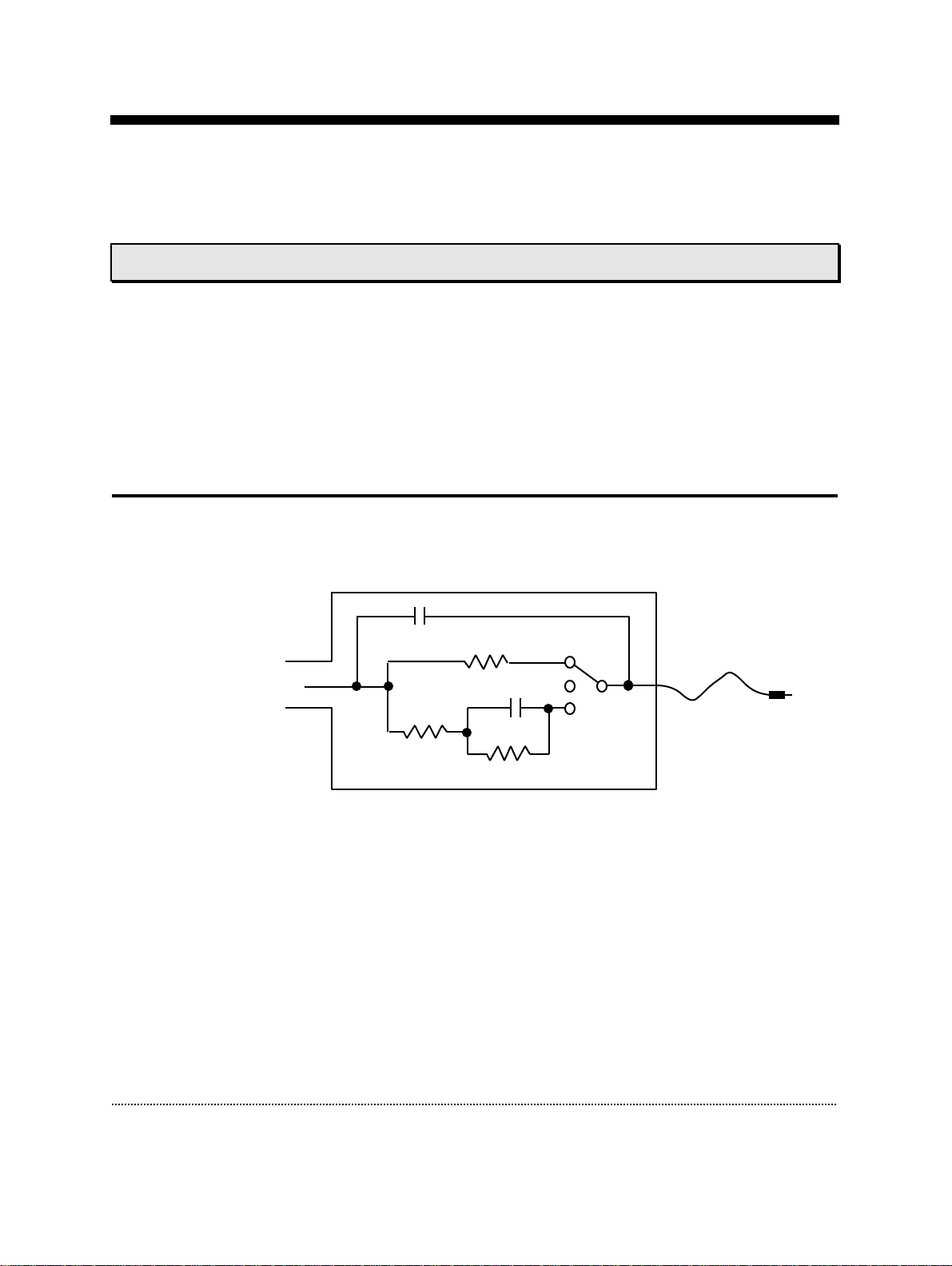
The Model Circuit MC 9
The model circuit connects to the probe input via a BNC adapter and the plug goes
to the black Gnd connector on the probe:
The model cell MC9
The model circuit provides a switch with three positions simulating the following
conditions typically observed during an electrophysiological experiment:
1. In the top position an ”open” pipette with a resistance of 10 MΩis simulated.
This mode is useful for applying a test pulse and for correcting offset
potentials.
2. The middle position simulates a pipette attached to the cell membrane after
the Giga-Ohm seal formation. In this setting only a capacitance of 6pF is left
over corresponding to the ”fast” capacitance of a pipette sealed to the cell
membrane. This mode allows you to test the C-fast compensation.
10 MΩ
22 pF
5.1 MΩ0.5 GΩ
6 pF
BNC
(to probe
input) Plug
(to GND
connector)

Testing the EPC9 EPC9 Manual 20
3. In the bottom position a ”model cell” in the whole cell patch-clamp
configuration is simulated. The ”input resistance” is 5.1 MΩ, the ”membrane
resistance” is 500 MΩand the ”membrane capacitance” is 22pF. This mode
lets you test the C-slow compensation and the current clamp mode.
Furthermore it is useful to check stimulation patterns you design within
PULSE.
Note: This model cell has a long “membrane” time constant (about 10 ms).
The following tutorial can be best executed with E9SCREEN. However, since PULSE
offers the same functionality with respect to the EPC9,you could use that program
instead. The figures shown were taken from E9SCREEN.
Step 1: Applying the Test Pulse
First, connect the model circuit to the probe input via a BNC adapter and plug the
black cable to the black ground connector on the probe. If E9SCREEN is not running
yet, start the program which is located in the E9SCREEN folder inside the HEKA folder.
Windows users might alternatively use the Start button to launch E9SCREEN from
Programs HEKA. The left side of the E9SCREEN window, the so called ”virtual front
panel”, provides a graphical representation of the EPC9 amplifier. The panel lets you
control all hardware settings of the amplifier(s) such as gain or filters. Signal display
is provided by an oscilloscope-like display in the right part of the window.
Table of contents
Other HEKA Laboratory Equipment manuals


Popular Laboratory Equipment manuals by other brands


Belden
Belden HIRSCHMANN RPI-P1-4PoE installation manual

Koehler
Koehler K1223 Series Operation and instruction manual

Globe Scientific
Globe Scientific GCM-12 quick start guide

Getinge
Getinge 86 SERIES Technical manual

CORNING
CORNING Everon 6000 user manual

Biocomp
Biocomp GRADIENT MASTER 108 operating manual


