HIRD GLASS KAPPEL HYDRAULICA 2000 User manual
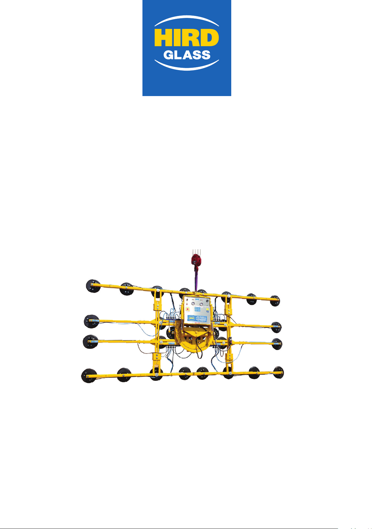
OPERATOR MANUAL
www.hird.co.uk
KAPPEL
HYDRAULICA 2000
www.hird.co.uk
DISCLAIMER - ALL INSTRUCTIONS ARE SUPPLIED FROM MANUFACTURER AND WHERE CORRECT AT TIME OF PRINT OM 1128-2
Northern (Head Office)
Tel: +44 (0)1482 227333
Western
Tel: +44 (0)1384 900388
Southern
Tel: +44 (0)203 174 0658
Central
Tel: +44 (0)1302 341659
www.hird.co.uk

OPERATOR MANUAL | KAPPEL HYDRAULICA 2000 www.hird.co.uk
Technical Description
The dual-circuit Hydraulica 2000 multi-purpose vacuum lifter is capable of lifting non-porous loads
of up to 2000kgs. It features 210o powered rotation up to 210o and hydraulic tilt from 0 to 90o.
It is a dual powered machine which can be powered by the on board maintenance free 12V dry cell
rechargeable batteries. Or by 110V supply. The built in charger allows the operator to recharge the
battery during the mains operation or overnight before lifting commences.
Safe operation is assured by four independent systems:
Two independent vacuum systems, each with its own vacuum pumps (3 per circuit), non-
return valve, vacuum sensor, vacuum gauge and alarm system. This ensures that should
one circuit loose vacuum due to breakage, etc the other circuit will still support the load.
Either circuit is capable of supporting the safe working load (SWL). During thorough
examination both circuits are independently proof tested to 1.5 times the SWL.
N.B. This does not mean that the lifter can be used to lift greater than the SWL.
At no tome must a loan more than the SWL be lifted;
If electrical power is lost during mains operation the batteries will automatically take over
to power the lifting in all its functions;
The pumps are controlled by vacuum sensors which automatically start the pumps and
regenerates the vacuum if a low vacuum condition (below 61%) is reached on either
circuit. This is accompanied by audible and visual warnings.
Pump application is reduced by a combination of the vacuum reserve tanks and vacuum sensors,
which switch off the pump when the vacuum reaches approximately 74% and only restarts when the
61% unsafe limit is reached. This limits the drain on the battery.
The individual pads are movable on the pad frame to cater for different sizes or odd shaped loads.
Shut off valves allow individual pads to be isolated should they not be required.
N.B. Although it is possible to apply the vacuum circuits individually the lifter MUST NEVER be
operated in this manner. Both vacuum circuits must be functioning correctly and MUST ALWAYS
be operated before attempting to lif the load. Failure to do so could lead to loss of the load with
potentially fatal consequences.
KAPPEL HYDRAULICA 2000

OPERATOR MANUAL | KAPPEL HYDRAULICA 2000 www.hird.co.uk
HEALTH AND SAFTY INSTRUCTIONS
General
1) The Hydraulica 2000 is designed in accordance with the relevant European standard
(EN13155:2003). However, operating errors and misuse will result in hazards:
a) To the life of the operator and others;
b) To the lifter and materials of the company and others;
c) To the correct and efficient operation of the device.
2) All persons involved with the set-up, operation and maintenance of the machine must read
and observe the following instructions. The personal safety of yourselves and others that may
encroach upon your operation is at stake.
3) Only operate the Hydraulica 2000 under the correct environmental conditions, to do otherwise
jeopardises health and safety, and will invalidate the Report of Thorough Examination to ensure
the Safe Working Load (SWL) of the lifters current configuration is adequate for the load to be
lifted.
Intended Use
4) The Hydraulica 2000 is intended for the carriage of gastight, dry materials with a solid smooth
surface. The load may be manually rotated through 270o and hydraulically tilted from 0 to
90o.. Use of additional and sufficient manpower is strongly recommended when preforming
the rotation manoeuvre. Other operations involving the lifting of gas permeable or foil coated
materials, wet or unstable loads, loads that are heavier than the SWL or operating outside
environmental guidelines or using the machine in the rain is regarded as contrary to intended
use. The manufacturer/supplier is not liable for any damage resulting from such misuse. That
risk lies entirely with the user.
5) Care is to ne take when operating this machine in areas of high electromagnetic disturbance,
e.g. HV power generation facilities, HV transformer sub-stations as this may lead to the
inadvertent release of materials. Where this work is carried out every opportunity must be taken
to isolate equipment from HV interference by ensuring all covers to distribution boxes, control
boxes, etc are closed.
6) Unauthorised alterations to the structure or operations controls of the device is prohibited for
safety reasons.
7) Intended use also requires observance of the operating manual and adherence to the conditions
for inspection and maintenance.
KAPPEL HYDRAULICA 2000

OPERATOR MANUAL | KAPPEL HYDRAULICA 2000 www.hird.co.uk
Emissions
8) The equivalent continuous A-weighted sound pressure level (LpA) is approximately 8odbA at a
distance of one meter whilst the pump warning siren is operating. This is below the first action
level as defined in the Control of Noise at Work Regulations 2005. However in confined areas
this level may be exceeded and personnel suffer hearing disturbance and should be issued with
the appropriate personal protective equipment.
Environmental Considerations
9) The lifter must not be used in the rain or on wet loads. Failure to observe this requirement may
lead to failure of the systems with potentially fatal consequences.
10) The operating temperature range is 0 oC to +35oC. The storage temperature range is -5 oC to
+50 oC.
Sources of Hazards
11) The lifting frame works on negative pressure (vacuum) to hold the gastight load. Any failure of
vacuum system may cause the load to release with potentially fatal consequences. Therefore,
as far as is reasonably practicable, all measures must be taken to avoid lifting the load over
personnel.
Organisational Measures
12) A job specific risk assessment and method statement must be prepared by a competent person
prior to the commencement of the task.
13) Always have the Hydraulica 2000 operating manual available on site.
14) No one under the age of 18 years old may operate this machinery.
Maintenance
15) User maintenance of the device is strictly limited to:
a) Pre-use inspection;
b) Battery charging;
c) Resetting of 2A and 25A circuit breakers.
16) Other than these operations all maintenance, inspection and testing must be carried out by
authorised and competent personnel only.
17) Never clean the pads with solvent based chemicals, this will remove the plasticiser and seriously
degrade the pads shortening their life and rendering them unsafe. In the event of serious
contamination of the pads, a mild solution of soapy water should be used. Care should be taken
that no water enters the system during cleaning via the holes on the pads.
18) As a designated “accessory for lifting” the Hydraulica 2000 is subject to a thorough examination
by a competent person every 6 months in accordance with the Lifting Operations and Lifting
Equipment Regulation 1998, Redulation 9(3)(a)(i).
KAPPEL HYDRAULICA 2000

OPERATOR MANUAL | KAPPEL HYDRAULICA 2000 www.hird.co.uk
TROUBLESHOOTING
Lifter fails to achieve 65% vacuum
1) Check whether all cups are in contact with the load.
Reposition cups if necessary
2) Check that nothing is stopping the vacuum lips on the cup from forming a seal. This may be cork
spacer pads, an outer lip that has curled under, etc.
Remove lifter and check load and pads, reposition lifter
3) Check the hose clamps for security and tightness
Tighten clamps, but only where necessary
4) Check the pipes for damage
Contact Peter Hird and Sons Ltd for pipe replacement
5) If after recertification the pump will still not achieve 65% vacuum contact Peter Hird and Sons Ltd.
Pump Fails to run when power is set to on
1) Check whether 25A circuit breaker S2 has tripped
Press S2 to reset, located on top of the function panel.
If S2 coninually needs resetting there is a problem within the function panel.
There are no user serviceable parts within and the lifter must be returned to Pete Hird and Sons Ltd.
2) Check whether the battery has sufficient charge.
Wither recharge the battery or use the lifter on mains power
3) If the lifter is on mains power, check the leads (and transformer if 110V)
Replace leads and/or transformer
4) If the lifter still does not function return to Peter Hird and Sons Ltd for investigation
Mains operation not possible (POWER light does not illuminate)
1) Check cables and site supply (and transformer if 110V)
Replace cables and transformer if necessary. Contact site service electrician about
restoring of power.
2) Check whether 2A circuit breaker S1 has tripped
Press S1 to reset, located on top of the function panel.
If S1 coninually needs resetting there is a problem within the function panel.
There are no user serviceable parts within and the lifter must be returned to
Pete Hird and Sons Ltd.
3) If the lifter still does not function return to Peter Hird and Sons Ltd for investigation
KAPPEL HYDRAULICA 2000

OPERATOR MANUAL | KAPPEL HYDRAULICA 2000 www.hird.co.uk
LIFTING AND POSITONING
1) Carry out pre-use check.
2) Position lifter on load within 40mm of center of gravity
3) Ensure all pads are in contact with unit surface and all relevant pad shut off taps are ON (in-line)
and quick release fitting are correctly connected (extension arms only)
4) Turn the power ‘ON’.
5) Press both vacuum actuation buttons on the remote control box until they click.
6) Ensure vacuum gauge reaches at least 65% and all warnings cease.
7) Carry out 50mm lift whilst observing vacuum gauge. Vacuum levels should not suddenly drop
under load.
8) Check stability of load, lower and adjust if necessary.
9) When confident of stability of load and vacuum, the load is raise and if required may now be
rotated and tilted to desired angle.
Always ensure that there is sufficient space to rotate and tilt the load.
10) The load may now be banked into position and final adjustments to tilt and/or rotation carried
out by fixers.
11) If mains power is being used it is essential that the cable has an unobstructed pathway both on
the ground and in the air to prevent snagging which could lead to a violent arresting of the lifter
and potentially loss of the load.
12) To release the load, both remote control buttons are lifted to release the vacuum then press the
red power switch and ensure all lights are off and vacuum gauge drop to ‘0’.
13) It is VERY IMPORTANT that the power switched to ‘OFF”. If the switch is left ‘ON” the operating
solenoids will burn out.
14) The Vacuum takes a few seconds to release, so it is vital that all the pads are free before the
crane or hoisted is raised. This prevent any residual vacuum in the system from lifting the load
whilst no power is applied to the pump.
KAPPEL HYDRAULICA 2000

OPERATOR MANUAL | KAPPEL HYDRAULICA 2000 www.hird.co.uk
LIMITED WARRANTY AND LIABILITIES
1) In principle, dependent upon type of supply our ‘Hire Terms and Conditions” or “Sales Terms
and Conditions’ are valid and apply.
2) Warranties and liability claims for injury to persons or material damage are limited to where it
can be proven that aforesaid injury or damage is due to negligence on the part of
Kappel or their authorised representative.
3) In particular the following conditions are strictly excluded from warranty or liability claims:
a) Device being used for lifting materials other than those covered by the intended use section
of the health and safety instructions;
b) Improper mounting, installation, operation or maintenance of the device;
c) Use of the device with safety or protective devices that are not operating correctly;
d) Device being transported, operated, mounted, installed, maintained or prepared in
contradiction of the advice as described in the health and safety instructions;
e) Unauthorised modification or alteration to the device;
f) Use of the device by personnel with inadequate knowledge of the operation of vacuum
devices.
g) Improper repair;
h) Natural catastrophe or force majeure.
KAPPEL HYDRAULICA 2000

OPERATOR MANUAL | KAPPEL HYDRAULICA 2000 www.hird.co.uk
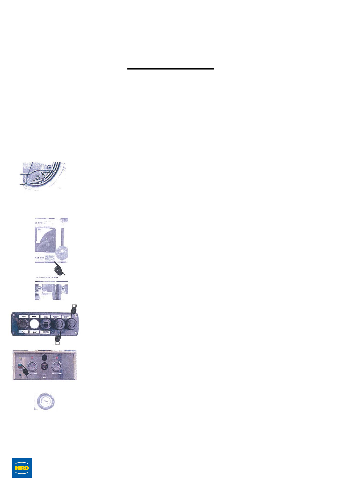
OPERATION
KAPPEL HYDRAULICA 2000
CHARGING THE BATTERY
1) Ensure that the mains supply voltage corresponds with the charger
voltage
i.e. 110 volts.
2) Unwind the supply able and any extension leads fully.
3) Plug the lad receptacle onto the plug fitted on the lifter prior to
inserting any other plugs. Failure to do so may cause the 2A witch S1
to trip.
4) Once the lead is firmly secured to the lifter, the other end may be
plugged into the mains or transformer.
5) The green POWER light should now illuminate and the battery
will begin to charge. Charging is fully automatic and will take
approximately 8 hours.
6) To check the amount of charge in the battery, press the Battery Test
button and the gauge will illuminate and indicate the percentage of
charge.
N.B. Never attempt to lift if the battery charge is indicating
below 20%.
7) If the Power light fails to illuminate, check the 2A trip S1 and reset if
required.
OPERATOR MANUAL | KAPPEL HYDRAULICA 2000 www.hird.co.uk
PRE-USE INSPECTION
KAPPEL HYDRAULICA 2000
Prior to starting any operations, the Provision and Use of Work Equipment
Regulations 1998 stated that the lifter must be inspected. Please note the
approved Vacuum Lifter Pre-Use Inspection Check List is available for free
download at TO ADD LINK HERE IF REQUIRED
1) Check the lifter for damage and distortion, particularly in the area of
the vacuum tanks and any welds.
2) Check the vacuum pads afor rips or tears that may affect the vacuum
lips. Check also for perishing of evidence of hardening, and for
cleanliness of the pads.
3) Check the vacuum pipes for any damage and security. Where the
extension arms are fitted pay particular attention to the security of the
quick release fixings.
4) Check the electrical cabling for any damage. Inspect the battery
connections for security.
5) Check battery has sufficient charge. Where the lifter is to be mains
powered, ensure the mains voltage matches that of the lifter
6) Check the test plate of the lifter for:
a) Safe Working Load (SWL), this will always show the maximum SWL.
The current Report of Thorough Examination must be consulted to
confirm the SWL in the configuration being used.
b) Serial number of lifter, and that if it matches the serial number of
the accompanying Report of Thorough Examination.
c) The last examination date matches that on the Report of Thorough
Examination and that the current date is within 6 months of the last
thorough examination.
7) Ensure all pad shut off valves are in the ‘OFF’ position, i.e. not in line
with the pipe.
8) Press both vacuum activation buttons on the remote control
9) Turn the pumps in using green button indicated
10) Ensure that all warning lights and sirens are on during the vacuum
build up.
11) Ensure vacuum reaches correct level on both circuits before pump
turns off
OPERATOR MANUAL | KAPPEL HYDRAULICA 2000 www.hird.co.uk
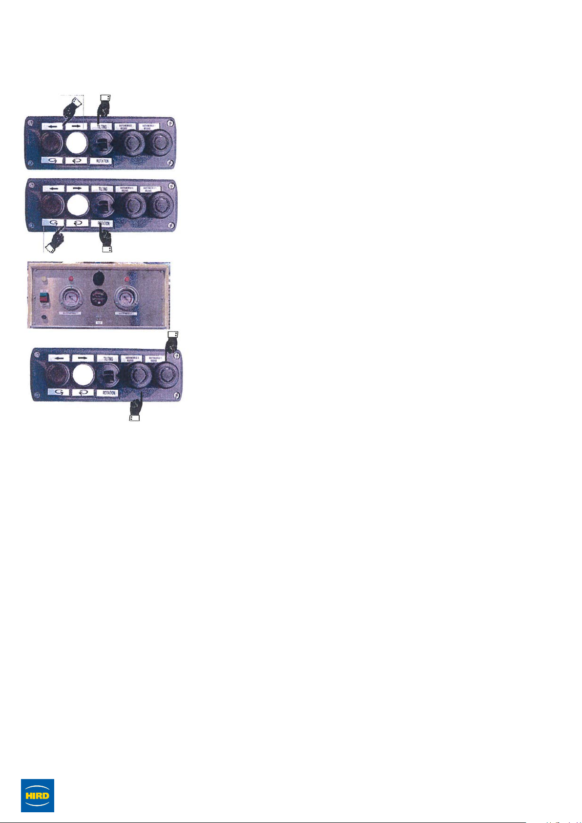
12) Select ‘TILTING’ on the remote control and using the
remote control buttons, check that the lifter tilts from 0 to
KAPPEL HYDRAULICA 2000
90oand back again freely.
13) Select ‘ROTATION’ on the remote control and using
the remote control buttons, check that the lifter rotates
clockwise and anti-clockwise freely.
14) Turn the power switch to ‘OFF: and pull both vacuum
actuation valves to release the vacuum and ensure the
vacuum gauge drops to 0.
15) Ensure all pad isolation valves are turned on
i.e. in line with the pipes.
16) Apply the lifter to a glass unit, turn the power on using
the green button, press both the vacuum application
buttons until they click. When the correct vacuum levels
are reached and all warnings are extinguished, record
the vacuum levels, leave the lifter applied and wait for a
period of 10 minutes. Inspect the gauges again and check
whether the levels have dropped 5% or more from the
recorded values. If so DO NOT USE go to step 17.
17) Remove the lifter clean the load and pads thoroughly. Repeat step
15. If the lifter is still loosing more than 5% over the 10 minute period
from either circuit, remove the lifter from service and label it “Out of
Service” and ring Peter Hird and Sons Ltd for more advice.
Safety Note 1
When using the extension arms it is imperative that the pipes from
the pads are correctly connected to the quick release fitting prior to
vacuum being applied. Failure to do so will isolate the relevant pad
from the vacuum system.
If the above condition is seen, return load to safe position before
trying to rectify, as any attempt to connect the pipe after the vacuum is
applied mat lead to loss of load, particularly if the pad is not in correct
contact with the load surface.

OPERATOR MANUAL | KAPPEL HYDRAULICA 2000 www.hird.co.uk
TRANSPORT & STORE
1) Do not set down the suction cups, nor try to apply them on a surface that is likely to
damage the sealing lips, such as: rough stone or concrete, sharp edges. The resulting
damage to the lips could impair the cups ability to seal when required and may lead to
the loss of the load.
2) Likewise, never place the cups down on a dusty or sandy area or one that is covered with
grit. This may lead to sharp grains becoming embedded in the pads. This may lead to
the pad not sealing correctly or damage to the surface being lifted.
3) Never lean the lifter against a surface for storage as the lips may become distorted or
the lifter may be knocked over and damaged. If it is necessary to lean the machine
against a surface ensure the pads are supported clear of the floor and the lifter is
adequately secured against falling.
4) The lifter should be transported and stored either on a smooth clean surface or by being
freely suspended.
5) Always ensure that the lifter is stored away from areas that are subject to rain, snow
or heavy condensation as the moisture may penetrate the electrical or vacuum system
causing severe damage and creating an electric shock risk and/or impairment of the
vacuum system.
6) Temperatures of -5oC should be avoided for storage as this may cause premature
perishing of the pads and render them unsafe and unusable.
7) Preferably the lifter should be stored on its own stand or transport frame in a warm,
dry atmosphere.
KAPPEL HYDRAULICA 2000
OPERATOR MANUAL | KAPPEL HYDRAULICA 2000 www.hird.co.uk
SAFETY DEVICES
The Hydraulica 2000 has several safety devices to prevent the loss of vacuum.
1) The non-return valves in the vacuum pumps prevent loss of vacuum when the pumps
guts off or fails.
2) The vacuum tanks create a vacuum to hold the load in the event of a vacuum pump
failure, It also prevents the pump switching on to often during normal operation, helping
preserve battery.
3) Vacuum gauges give a direct indication of the percentage of the vacuum in both circuits.
4) Vacuum sensors with in-line warning lights and siren to indicate when vacuum has
dropped to an unsafe level in either circuit
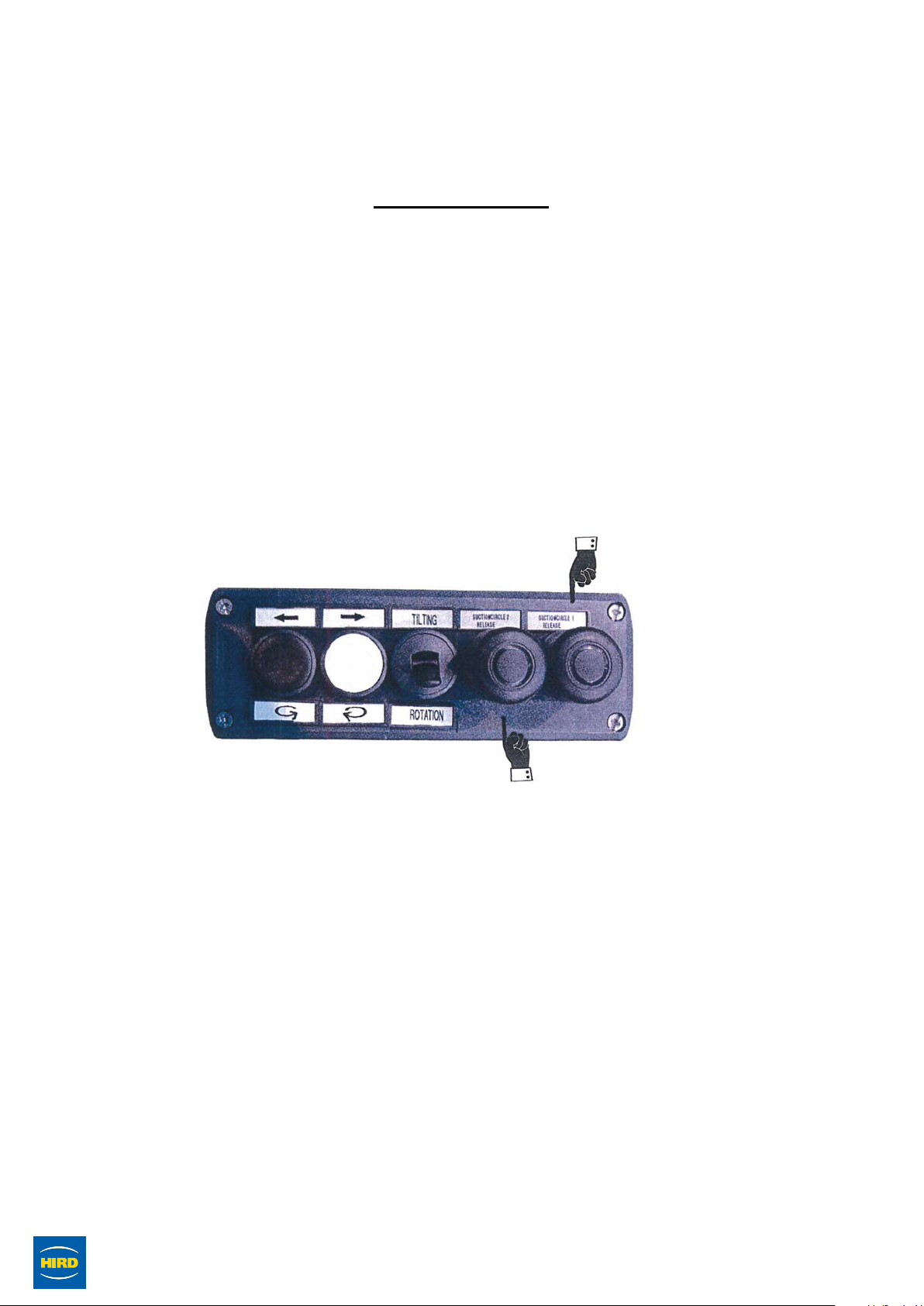
5) The remote control has a “press to apply and lock – pull to release” control knob for
each circuit to prevent the inadvertent release of vacuum.
KAPPEL HYDRAULICA 2000

PRE1125-2
Daily Pre-Use Checklist
Vacuum Lifter
Machine Model: Site Name:
Date Week Commencing: Fleet No: Address:
Inspected by:
Northern (Head Office) Tel: +44 (0)1482 227333
Central Tel: +44 (0)1302 341659
Western Tel: +44 (0)1384 900388
Southern Tel: +44 (0)203 174 0658
www.hird.co.uk
PRE1125 Kappel Hydraulica 2000
Kappel Hydraulica 2000
Result of Inspections: List defects or state “No Defects”
Signature: Name: Date:
Daily Pre-use Checks M T W T F S S COMMENTS
1Are all operators manuals present and readable
2Is the Report of Thorough Examination (LOLER) in date
3Complete a visual walk around / Inspection for any noticeable defects
4Are all safety information decals present and readable
Check the following components or areas for damage, or missing parts & unauthorised modifications:
5Is the lifting attachment free from defects and safe to use
6Vacuum pads for rips, tears, quality and cleanliness
7Vacuum pipes and connections (in particular quick release fittings)
8All extension arms are present and free from defects
(where applicable)
9Make sure all individual pad shut off valves are open
(where applicable)
10 Electrical components, wiring, connectors,
11 Check input mains voltage corresponds with charger voltage
(110v or 240v)
12 Charger
13 Check battery has sufficient charge
14 Are rotation and tilting movements functional
15 Check handles security
16 Check remote for any damage or defects (where applicable)
17 Check operation buttons / switches are working and free from defects
18 Energise vacuum on non porus surface
19 Are lights and audible alarms on during vacuum process
20 Does the vacuum reach sufficient level, before switching off
(see gauges)
21 Does battery gauge illuminate when pump switches off
If NO - DO NOT USE
22 Check Safe Working load of vacuum - is it suitable for
the proposed load
23 Carry out full function test
Is the machine safe to use? (please circle)
YES YES YES YES YES YES YES
NO NO NO NO NO NO NO
Operator’s Initials
Table of contents
Other HIRD GLASS Lifting System manuals


Popular Lifting System manuals by other brands

BLUM
BLUM SERVO-DRIVE uno installation instructions

Valx
Valx Landing leg S Installation and operation instructions

Ravaglioli
Ravaglioli RAV232 NL manual

Ravaglioli
Ravaglioli RAV8065.1.65MB Translation of the original instructions

Nussbaum
Nussbaum 2.30 SPL Operating Instruction and Documentation

Terex
Terex Genie GR -12 Service manual

EKKO
EKKO EB12E Series user manual

Powerbuilt
Powerbuilt 941877GCF instruction manual

Aqua Creek
Aqua Creek PORTABLE PRO POOL-AT LIFT Installation and operating instructions

CRESTO
CRESTO RESQ RED Pro III Instructions for use

Kleton
Kleton MP007 instruction manual

AMGO Hydraulics
AMGO Hydraulics 409-DP Installation and service manual


