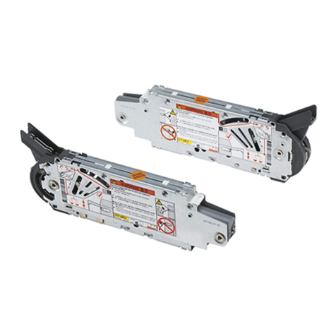
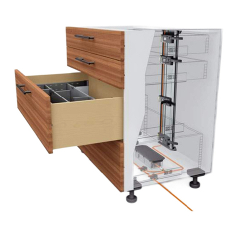
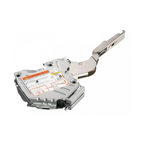
BLUM SERVO-DRIVE uno User manual

by Blum
www.blum.com
uno
SERVO-DRIVE
Installation instructions

2
Table of contents
Using the installation instructions��������������������������������������������������������������������������������������������������������������3
Intended use ����������������������������������������������������������������������������������������������������������������������������������������������3
Safety ���������������������������������������������������������������������������������������������������������������������������������������������������������4
Structural changes and spare parts ����������������������������������������������������������������������������������������������������������6
Disposal �����������������������������������������������������������������������������������������������������������������������������������������������������6
Blum plug-in transformer safety distance �������������������������������������������������������������������������������������������������7
Troubleshooting �����������������������������������������������������������������������������������������������������������������������������������������7
Overview drawing ��������������������������������������������������������������������������������������������������������������������������������������8
Function �����������������������������������������������������������������������������������������������������������������������������������������������������8
Assembly����������������������������������������������������������������������������������������������������������������������������������������������������9
Adjustment �������������������������������������������������������������������������������������������������������������������������������������������������9
Blum distance bumper�����������������������������������������������������������������������������������������������������������������������������10
Cabling overview drawing������������������������������������������������������������������������������������������������������������������������10
Blum plug-in transformer assembly���������������������������������������������������������������������������������������������������������10
Cable diagram������������������������������������������������������������������������������������������������������������������������������������������10
Start-up ����������������������������������������������������������������������������������������������������������������������������������������������������12
Cover cap assembly ��������������������������������������������������������������������������������������������������������������������������������16
Replacing the SERVO-DRIVE switch battery������������������������������������������������������������������������������������������16
Removal ��������������������������������������������������������������������������������������������������������������������������������������������������17

3
EN
Using the installation instructions
Please read the installation instructions and safety information before
SERVO-DRIVE start-up�
We recommend that you use the orientation diagram for easier identi-
fication of the parts being described�
These installation instructions can be used for the SERVO-DRIVE
electric motion support system for AVENTOS HF, AVENTOS HS,
AVENTOS HL and AVENTOS HK�
However, only AVENTOS HF is shown as an example in the illustra-
tions�
Please see the special AVENTOS installation instructions for the
assembly steps for the mechanical AVENTOS HF, HS, HL and HK
fittings without SERVO-DRIVE�
Intended use
SERVO-DRIVE supports the opening and closing of lift systems and
may only be used under the following conditions:
• in dry, enclosed rooms
• in combination with AVENTOS lift systems from Julius Blum GmbH
within the permitted technical specifications
• in combination with a Blum plug-in transformer�
➢The total cable length of 2 metres must not be exceeded�
NOTE

4
Safety
SERVO-DRIVE complies with current safety standards�
Nevertheless, there are certain risk factors if these installation instruc-
tions are not followed� Please be aware that Julius Blum GmbH is not
responsible for incidental or consequential damages that may arise if
these installation instructions are not followed�
• All national standards must be followed for SERVO-DRIVE assem-
bly� This includes, in particular, those related to the mechanical
safety of moving parts and electrical cabling�
• Only qualified technicians may install and replace Blum compon-
ents, modify the position of the Blum plug-in transformer or modify
any cabling�
• The device may only be connected to a power supply, the voltage,
type of power and frequency of which correspond to those listed on
the rating plate (see Blum plug-in transformer)�
• The outlet must be freely accessible�

5
EN
• Maintain the safety distances to the Blum plug-in transformer that
are listed in the installation instructions�
• Make sure that there can be no ingress of moisture into the Blum
plug-in transformer and drive unit�
• Before starting repair or maintenance work, switch off the outlet
to which the Blum plug-in transformer is connected or pull out the
mains plug�
• The drive unit, Blum plug-in transformer and SERVO-DRIVE switch
should only be cleaned with a damp cloth because ingress of mois-
ture and aggressive cleaning materials
can damage the electronics�
• Do not touch the area around the lever during the opening and
closing motion�
• No damaged parts should be used�
• Sharp edges may damage the cables�
• Neither the Blum plug-in transformer nor any cabling should come
into contact with moving parts�
• Never take apart a drive unit or a SERVO-DRIVE switch�
• Only one drive unit may be used per Blum plug-in transformer�
WARNING
Danger of death from electric shock!
➢Never open a Blum plug-in transformer�
WARNING
There is a danger of injury if the lever springs
upwards.
There is a danger of injury from the lever springing
upwards when the front is removed�
➢Do not push down on lever arm, remove it
instead�
➢Do not connect the plug-in transformer to the
power supply while the fronts are unattached�

6
Warning signs and danger symbols
WARNING indicates a danger that could lead to
death or serious injury if not avoided�
This NOTE sign indicates information that
should be observed�
WARNING
NOTE
Structural changes and spare parts
Structural changes and replacement parts not approved by the ma-
nufacturer affect the safety and functionality of SERVO-DRIVE and
are, therefore, not allowed�
• Only use original spare parts from Julius Blum GmbH�
• Blum components designed for this purpose are the only devices
that should be connected to the Blum plug-in transformer�
• The cable from the plug-in transformer to the drive unit may not be
extended�
Disposal
• All SERVO-DRIVE electronic components, including batteries,
should be disposed of in a separate collection for electrical and
electronic appliances as per local regulations�

7
EN
Blum plug-in transformer safety distance
Troubleshooting
For troubleshooting information, please go to:
www�blum�com/sd/troubleshooting
➢The dimensions in the drawing take into account the safety
distance�
NOTE
A safety distance of 30 mm must be maintained for air circulation;
otherwise, there is a risk that the Blum plug-in transformer
could overheat�

8
5
68
9
12 3 47
Overview drawing
Lift mechanism
Telescopic arm or lever arm
Drive unit with LED display
Cover cap
SERVO-DRIVE switch with battery display
Blum plug-in transformer with LED display
Blum distance bumper
Front
Cabinet
1
2
3
4
5
6
7
8
9
Electric motion support system
The SERVO-DRIVE switch triggers the automatic opening and closing action of SERVO-DRIVE for
AVENTOS�
Press on the front
➢the lift system opens automatically�
Press on the SERVO-DRIVE switch
➢the lift system closes automatically�
The lift system can be opened or closed manually without restriction without damaging
SERVO-DRIVE for AVENTOS�
Manual operation
➢Manual opening of the lift system by
moving it upwards�
➢Manual closing of the lift system by mo-
ving it downwards�
Function

✓✓
75°
pp
NBY
1
65
4
3
2
9
AVENTOS HF / HS / HL / HK
AVENTOS HF / HS / HL AVENTOS HK
EN
Distribution cable assembly and connecting node assembly
Drive unit adjustment
SERVO-DRIVE for AVENTOS
Drive unit assembly
➢Before SERVO-DRIVE for AVENTOS assembly, the lift mechanisms
must be set so that the front remains open in different positions�
➢If required, install the opening angle stop only after drive unit assembly
and before the reference run�
NOTE
➢The telescopic arm and/or lever arms must be in the completely open
position for drive unit assembly�

DMJD
L
✓
10
AVENTOS HF / HS / HL
AVENTOS HK
SERVO-DRIVE switch assembly
➢The drive unit can only be locked when the orange slide is no longer
visible in the view window�
NOTE
NOTE
The drive unit can only be locked when the drive unit is inserted completely into the lift mechanism�

max 2000
1
2
3
11
EN
Cabling overview drawing
Blum distance bumper
Assembly in the front
Aluminium frame: assembly in the cabinet side�
➢Do not glue the Blum distance bumper
NOTE
Blum plug-in transformer with LED display
Distribution cable
Drive unit
Cable diagram
SERVO-DRIVE for AVENTOS
Back cabling
Upper cabling
➢Only one drive unit may be connected per plug-in transformer�
➢The total cable length of 2 metres must not be exceeded�
NOTE
1
2
3

12
1
2
3
AActivating the SERVO-DRIVE switch
Setting up the wireless connection between the SERVO-DRIVE
switch and the drive unit�
The SERVO-DRIVE switch can be activated with only one drive unit�
Press the <SWITCH> button
until the LED display flashes green�
Press the SERVO-DRIVE switch
until the LED display lights up green continuously�
Repeat procedure A 1–2 for all additional SERVO-DRIVE switches in
the cabinet�
E-training Lights up continuously Flashes
Start-up

13
B
1
3
2
4
EN
Carrying out reference run
The drive unit recognises the required parameters using the refe-
rence run�
Reference run is required: LED flashes
Press on front: the reference run starts automatically
Close the front manually
Front opens and closes twice automatically: under no circumstances
should you try to manually interrupt or stop the procedure�
Operation Lights up continuously Flashes
NOTE
If the reference run is interrupted, it should be reset – see Reset
Motion E 1� Restart reference run�

14
C
1
3
2
4
5
Activating synchronisation
Up to three drive units can be synchronised allowing them to move
simultaneously� This function is required for several cabinets with a
uniform front�
Activating the SERVO-DRIVE switch → see A 1–3�
Press the <SYNC> button for the first drive unit
until the LED display flashes green�
Press the <SYNC> button for the second drive unit
until the LED displays for both synchronised drive units light up green
continuously�
Repeat procedure C 2–3 for all additional drive units�
Carry out reference run → see B 1–4�
E-training Lights up continuously Flashes
If there is an activation error, reset the functions of all drive units →
see Reset Wireless F 1�
NOTE
Re-activate the SERVO-DRIVE switch, synchronisation and reference
run → see A 1–3, C 2–4 and B 1–4�

15
D
1
2
3
4
5
6
7
EN
Activating collision avoidance
To avoid the collision of fronts, drive units (max� 6) are linked so that
only one front can be opened at a time� A front is prevented from
opening as long as a linked front remains open�
Activating the SERVO-DRIVE switch → see A 1–3�
Press the <COLL> button for the first drive unit
until the LED display flashes green�
Close the front manually
Open the second front manually
Press the <COLL> button for the second drive unit
until the LED displays for both drive units light up continuously green�
Repeat procedure D 2–5 for all additional cabinets�
Carry out reference run → see B 1–4�
E-training Lights up continuously Flashes
If there is an activation error, reset the functions of all drive units →
see Reset Wireless F 1�
NOTE
Re-activate the SERVO-DRIVE switch, collision avoidance and refe-
rence run → see A 1–3, D 2–6 and B 1–4�

16
E
F
Reset Motion
Reset Wireless
Replacing the SERVO-DRIVE switch battery
Cover cap assembly
Press the <Reset Motion> button using a pen
(for at least 3 seconds) until the LED display flashes quickly�
Press the <Reset Wireless> button using a pen
(for at least 3 seconds) until the LED display flashes quickly�
Resets the reference run and enables a new reference run to be
started�
Deactivates all functions: all activated SERVO-DRIVE switches of the
respective drive unit are deactivated�
➢Open the SERVO-DRIVE switch and
remove the battery�
➢Insert the new battery (type CR2032)
and close the SERVO-DRIVE switch
– note proper pole connection�
When the battery power begins to weaken, the battery display (LED) will begin to flash red�
➢The SERVO-DRIVE switch battery must not be recharged or discarded into fire�
NOTE

17
EN
Distribution cable
SERVO-DRIVE for AVENTOS
Removal
WARNING
Danger of electric shock
➢Before starting repair or maintenance work, switch off the outlet
to which the Blum plug-in transformer is connected or pull out the
mains plug�

Julius Blum GmbH
Beschlägefabrik
6973 Höchst, Austria
Tel.: +43 5578 705-0
Fax: +43 5578 705-44
www.blum.com
MA-707/1EN · 02.17 · © Copyright by Blum
Other manuals for SERVO-DRIVE uno
3
Table of contents
Other BLUM Lifting System manuals
Popular Lifting System manuals by other brands

HALDER
HALDER EH 22352 Translation of the original operating instructions

WPG
WPG MRT4 Series instruction manual

Ravaglioli
Ravaglioli KPS324 H2 Translation of the original instructions

Mec
Mec 1532ES Operator's manual

Lifter
Lifter MX 510 Use and maintenance manual

EZ-ACCESS
EZ-ACCESS PATHWAY 3G SS28 Assembly manual