HISAKA UX-005A User manual

Plate Heat Exchanger
5 “Slit-In” Type Gasketting Manual
Introduction
About this document
In addition to this document, the Manuals for HISAKA PHEs consist of the following six documents. Read them thoroughly and
understand the precautions regarding the safety of the equipment and its functions before handling the equipment.
1 Installation Manual, 2 Operation and Maintenance Manual, 3 Gasketting Manual, 4 Plate Cleaning Manual,
6 Mixed Gasket Materials Manual, 7 Strainer Maintenance Manual.
You can also download these documents on our company website. http://www.hisaka.co.jp/english/
This document is the operation and maintenance manual for “Slit-in” type plates of plate heat exchangers (PHE) to which gaskets
are installed without adhesives. Refer to the separate operation and maintenance manual for food product PHE
(FX-A Series).
This document is created for a person who fully understands the language it is written in. If a person, who is not able to understand
the language written herein, will handle the equipment, please provide safety instructions to the personnel/operators.
The PHE supplied may differ from the drawings and pictures in this document depending on the optional parts if any. Also, for the
purpose of explanation, the drawings and pictures in this document may omit the details, accessories, or the like.
Changing the contents of this document, in part or in whole, or using this document for anything other than its intended purpose is prohibited.
About gasket use
To prevent injury and damages, do not use the gaskets other than for their intended purpose and specifications. Also, during
maintenance, follow the instructions of related documents.
About worker limitations
PHE maintenance should be carried out by a worker who has received training in safety and danger prevention.
Work in high places should be carried out by a worker who fully understands the danger of the work and has received training in
safety and danger prevention.
Export Regulations on the Equipment
In case of export of HISAKA PHE and its component parts such as plate, gasket and so on, please follow the local law and
regulations.
Disposal of the Equipment
Do not incinerate gaskets. Incinerating gaskets releases toxic gas and is extremely dangerous.
Any unnecessary gasket should be disposed as industrial waste in accordance with international, national, prefectural, and
municipal regulations.
Disclaimer
HISAKA accepts no liability for any failures in the function or performance of the equipment caused by use of any other than
genuine parts.
HISAKA accepts no liability for any injuries or damage borne by the user, caused by use of any other than genuine parts.
HISAKA accepts no liability for any failures in the function or performance of the equipment caused by use of this equipment in a
manner that does not adhere to the procedures indicated in this manual.

“Slit-in” Manual
Table of Contents
1 Safety Precautions P1
2 “Slit-in” Plates and Gaskets P2
3 “Slit-in” Gasketting Procedures P2 to 4
4 “Slit-in” Gasket Removal Procedures P4
5 Plate Disassembly and Assembly P4
6 D-Plate Gasket Installation Procedures P4
7 Other Precautions P4
8 Inquiries P5 to 7
P1
1 Safety Precautions
Read through this manual carefully before use and use the PHE properly as indicated.
If you have any questions, please inquire with our company.
Precautions are categorized using the following symbols.
WARNING
This symbol indicates content where mishandling could result in death or severe injury.
CAUTION
This symbol indicates content where mishandling could result in injury or property damage.
NOTE This symbol indicates important matters and/or useful information.
Meanings of Symbols
Indicates items that are
"prohibited (something that you must NOT do)".
Indicates items that are
"mandatory (something that you must do)".
WARNING
Do NOT loosen PHE's tightening bolts/nuts except for maintenance work.
The PHE could come apart if tightening bolts/nuts are loosened before installation.
Do NOT use tightening bolts with loosened bolt heads.
If the bolt head loosens and the bolt head (nut) comes off the bolt, it could fly off at high
speed. This is dangerous and contact could cause serious injury or property damage.
Do NOT use a flange gasket for the nozzle of heat exchangers with synthetic
rubber covering.
Sealing performance could be decreased and it could be a cause of leaking.
(Flange gaskets are required for nozzles with metal covering.)
Do NOT incinerate gaskets.
Incinerating gaskets releases a toxic gas and is very dangerous.
Any unnecessary gaskets should be disposed as industrial waste in accordance
with international, national, prefectural, and municipal regulations.
For the industrial waste treatment company, use a company that has received
permission from the prefectural governor.
In general, do NOT perform pneumatic test for medium and large size PHE.
For small size PHE, do NOT perform pneumatic test at the same pressure as
hydrostatic test pressure.
If a leak occurs during a pneumatic test using compressed air or nitrogen, it is extremely
dangerous as, in addition to the test pressure, volume expansion causes an impact.
In general, do NOT perform a pneumatic test in excess of 0.75 MPaG.
Install a protective cover on heat exchangers that handle high temperatures,
high pressure, or dangerous fluids such as strong acids or strong alkalies.
If a dangerous fluid leaks, it could cause a serious accident.
Make sure that the operation is stopped, the internal pressure is "0", and the
fluid temperature has sufficiently dropped before disassembling the PHE.
If a fluid sprays out from the heat exchanger interior during disassembly, it could
cause burns or lacerations.
Do NOT operate in excess of the design conditions
(temperature, flow rate, pressure, etc.).
It may cause deformation of the heat transfer plates or leakage. Also, the required
performance may not be achieved.
Do NOT loosen the thermometer, pressure gauge, tightening bolts and nuts, or
any other accessories during operation and when the PHE are pressurized.
If fluid splashes from the PHE during disassembly, it may cause burns or lacerations.
Perform gasket replacement in a well-ventilated area or area with ventilation
equipment.
The gasket dedicated adhesives "S-1" and "F-2" contain organic solvents. Breathing
the volatile ingredients for a long time may cause symptoms such as headache,
dizziness, and nausea. Should these symptoms occur, move somewhere with fresh
air and rest, stay calm and warm, and seek medical attention.
Do NOT use tightening bolts with damage such as significant rust or cracks.
If a tightening bolt breaks during operation or during disassembly, not only will the
fragments fly off, but there is also danger of the fluid in the heat exchanger interior
spraying out.
CAUTION
Do NOT touch the side of the heat exchanger element (edge of the heat
transfer plates).
The edge of a heat transfer plate is very sharp and may cut you.
Be sure to wear cut-resistant gloves whenever touching the heat transfer plates.
Request an expert to perform piping work, and review the assembly drawings
with them beforehand to ensure that connections are properly made.
Work performed by inexperienced personnel can result in a faulty or improper
connection. An improper connection can result in failure to provide the specified
performance or an equipment malfunction.
Do NOT place objects on the heat exchanger.
Doing so may cause deformation of heat transfer plate or a falling object may
cause injury during operation.
Do NOT touch anything the side of the heat exchanger element (edge of the
heat transfer plates).
Deformation of the heat transfer plate may cause damage to the plate gasket and
result in leakage.
Secure working space around the PHE.
Installation and piping design must take into account the working space required
for using disassembly and installation tools.
In general, do NOT remove the stud bolts on the heat exchanger nozzles.
Removing the stud bolts may cause damage on the threads.
If it is absolutely necessary to remove them, remove them carefully so as not to
damage the screw threading on the stud bolt and the frame. Also, stud bolt removal
shall be done at the customer's liability.
Clean the piping interior before connecting.
Clean piping thoroughly so that no debris enters the PHE.
Select flange gasket material that is suitable for the fluid specifications.
Flange gaskets are required for tube flange and metal boot types.
Do NOT weld or attach any piping support to the frame, guide bar, or guide
bar support.
Such welding may cause thermal damage to gaskets, or the attached part may
cause interference that prevents parts from fulfilling their function. Furthermore, the
installed part will be an obstacle and will prevent disassembly.
Install sufficient support for piping connected to the PHE.
A large piping load to the PHE may cause the frame to become deformed or
leakage.
Do NOT allow debris or foreign material to get inside the PHE.
The clearance of the PHE is quite narrow, such that it can be easily clogged by
debris or foreign material. When flushing the piping, take measures such as
installing a temporary strainer at the inlet piping or bypassing the PHE in order to
prevent debris or foreign materials from entering the PHE.
Perform maintenance of PHE that handle dangerous fluids, such as a strong
acids or alkalies, in an environment that has wastewater treatment equipment.
Process waste fluid in accordance with the law and regulations. Be careful not to drain
liquid into a river or ocean area. If untreated liquid leaks, take measures in accordance
with the "Material Safety Data Sheet (MSDS)" for the treatment liquid you used.
Do NOT allow the fluid to freeze.
In cold areas, remove the fluid inside the heat exchanger and empty the equipment
before storing it.
P2
2 “Slit-in” Plates and Gaskets
“Slit-in” plates are indicated by the letter "A" at the end of the model number indication. (Examples: UX-016A and UX-216A)
“Slit-in” plates have slits (holes) that are used for fixing gaskets to the plate.
These slits (holes) are located on the outside of the plate gasket groove and in the port holes (excluding UX-005A and
UX-01A).
“Slit-in” gaskets are indicated by the letter "A" in front of the material indication. (Examples: A-NBR and A-EPDM)
“Slit-in” gaskets have protrusions for fixing the gasket to a plate.
Handle gaskets with care because a protrusion can be cut easily.
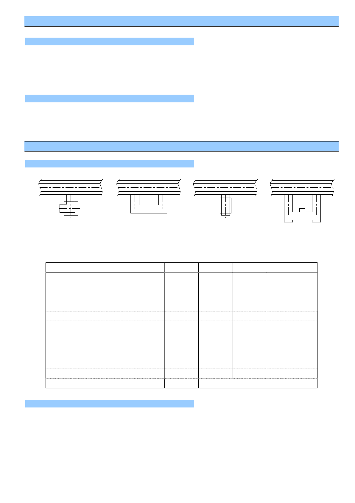
3 “Slit-in” Gasketting Procedures
There are four type of protrusions depending on each PHE model (Fig.1).
Fig. 1 Type of Gasket-Fixing Protrusions
Table 1 Type of Gasket-Fixing Protrusions by Model
Model L-type O-type I-type Hook-lock type
UX-005A
RX-01A
WX-10A
CX-10A
- - -
UX-01A, 20A, 40A -
UX-10A, 30A
RX-10A, 30A, 50A
SX-10A, 30A, 30SA, 40A, 70A
LX-00A, 10A, 20A, 30A, 40A, 50A
GX-20A
- -
EX-11A, 15A - - -
CX-01A - - -
1) Press the gasket protrusion at point A by hand for inserting into the slit (hole) on the plate as shown in Fig. 2.
2) Keep pressing at point A by hand, press point B to the plate surface.
It is more effective and secure to use a flat-blade screwdriver or similar tool than by hand.
2-1 Plates
2-2 Gaskets
3-1 Type of “Slit-in” Gasket Protrusions
3-2 Procedures for Setting L-type Protrusions
L-type O-type I-type Hook-lock type

P3
Fig. 2 Procedures for Setting L-type Protrusions
Set the gasket body into the plate groove properly. Press the gasket in point C as shown in Fig. 3 and 4 with pressing the
protrusion in point A and B for O-type / point A for I-type.
Fig. 3 O-type Protrusion Setting Procedures Fig. 4 I-type Protrusion Setting Procedures
Set the gasket body into the plate groove properly. Press the gasket in point C as shown in Fig. 5 with pressing the protrusion in
point A and B.
Fig. 5 Procedures for Setting Hook-Lock Type Protrusions
1) In case of no slit on plate, cut the protrusion of Gasket (* part in Fig.6) with scissors as below Fig.6 and 7.
Fig. 6 Part Names Fig. 7 Cutting Procedures
3-3 Procedures for Setting O-type/ I-type Protrusions
3-4 Procedures for Setting Hook-Lock Type Protrusions
3-5 Procedures for Setting Gaskets without Port Hole (Excluding UX-005A and UX-01A)
Before Cutting
After Cutting
O-type Protrusion
I-type Protrusion
A
C
A
B C
A
C B
L-type Protrusion
Gasket Body
Slit
Plate
A
A
B
L
-
type
Protrusion
Plate
a-a Cross-section
a
a
Hole
No Hole
Double-Seal Side
Plate
Gasket
Protrusion*
Double Seal Connection
Double Seal of Transfer Surface Side

P4
2) After cutting the protrusion of the port hole for UX-30A, UX-40A or SX-40A, Peel back one side only of Sekisui Double-Faced
Tape No. 575. Fix double seal connection to the plate by the tape. Refer to below Fig. 8.
Fig. 8 Procedures for fixing by Tape
Check the setting of all gasket protrusions properly.
4 “Slit-in” Gasket Removal Procedures
Push up gasket protrusion from the backside of the plate. Pay attention not to cut protrusions. Wear cut-resistant gloves while
working this procedure to prevent injury.
5 Plate Disassembly and Assembly
When disassembling plates, some gasket protrusions might slip out of the slits. Reset the slipped out protrusions into their slits
before assembly and tighten frame.
6 D-Plate Gasketting Procedures
Each model has different gasketting procedures. Refer to "3. Gasketting Manual" of your PHE model for gasket names and
installation positions.
This section indicates the gasketting procedures for D-gasket, “Slit-in” type. Models not indicated in table-2 are regardless of
“Slit-in” type, adhesive is necessary for D-gasket setting. Refer to "3. Gasketting Manual" for gasketting by adhesive.
Table 2 D-Plate Gasketting Procedures for “Slit-in” type
Models: UX-005A, UX-30A, SX-40A and SX-70A
[NOTE]
The figure shows model UX-005A. Plate type and
protrusion position are different depending PHE model.
Refer to "3. Gasketting Manual" of your PHE for gasket
names and type.
7 Other Precautions
1) Wash and remove solid scales and/or other foreign material before assembly.
2) Long period use make double seal of transfer surface side (refer to Fig. 6) insufficient fit to plate groove.
Existing gasket still can be re-used. Fix it as same procedure as 3-5 2)
3-6 Set Checking
Gasket (Port Hole Side)
Gasket (Heat Transfer Side)
Fixed by Tape
Double Seal Connection
Slit Adhesive

P5
8 Inquiries
Contact info for inquiries
HISAKA WORKS, LTD., Heat Exchanger Div., Sales Department
Osaka: 2-1-48, Higashi-Konoike-cho, Higashi-Osaka, Osaka, 578-0973, Japan Tel : +81-(0)72-966-9601
Fax : +81-(0)72-966-8923
Tokyo: KYOBASHI OM BLDG. 1-19-8, Kyobashi, Chuo-Ku, Tokyo, 104-0031, Japan Tel : +81-(0)3-5250-0760
Fax : +81-(0)3-3562-2759
Nagoya: Fujifilm Nagoya Bldg. 12th Floor, 1-12-17, Sakae, Naka-Ku, Nagoya,
Aichi 460-0008, Japan
Tel : +81-(0)52-217-2491
Fax : +81-(0)52-217-2494
Hokkaido: Sapporo Shiraishi Daiichi Seimei Bldg. 6-1-20, Higashi Sapporo 3jo,
Shiraishi-Ku, Sapporo, Hokkaido 003-0003, Japan
Tel : +81-(0)11-868-8010
Fax : +81-(0)11-868-8011
Onomichi: 14-15, Nishigosho-cho, Onomichi, Hiroshima, 722-0037, Japan Tel : +81-848-21-2750
Fax : +81-848-21-2751
URL : http://www.hisaka.co.jp/english/
Global Network
HISAKAWORKS S.E.A. SDN. BHD. (MALAYSIA)
No.2, Jalan TP2. Taman Perindustrian SIME UEP, 47600 Subang Jaya, Selangor,
Malaysia
Tel : +60-3-8081-4185
E-mail : [email protected] Fax : +60-3-8081-7185
HISAKAWORKS S.E.A. SDN. BHD. PENANG BRANCH (MALAYSIA)
No 2680, 2nd Floor, Jalan Chain Ferry, Taman Inderawasih, 13600 Perai, Penang,
Malaysia
Tel : +60-16-203-2527
Fax : +60-4-390-8588
E-mail : [email protected]
HISAKAWORKS S.E.A. SDN. BHD. JOHOR BRANCH (MALAYSIA)
30-02, JalanMolek 1/10, Taman Molek, 81100 Johor Bahru, Johor, Malaysia Tel : +60-16-228-4209
E-mail : [email protected]
HISAKA WORKS(THAILAND)CO., LTD. (THAILAND)
12th Floor, 825 PhairojKijja Tower, Debaratana Road, Bangna-Nua, Bangna, Bangkok
10260, Thailand
Tel : +66-2-744-3287
E-mail : [email protected] Fax : +66-2-744-3286
HISAKA WORKS(THAILAND)CO., LTD. SATTAHIP SALES OFFICE (THAILAND)
222/28, Moo.10, Eastiny Park 5 Village, Bang Saray, Sattahip, Chonburi 20250, Thailand
Tel : +66-3-819-9819
E-mail : [email protected] Fax : +66-3-819-9820
HISAKAWORKS SINGAPORE PTE LTD. (SINGAPORE)
No.18, Boon Lay Way, #02-118, Trade Hub 21, Singapore 609966 Tel : +65-6-897-8489
E-mail : heatex@hisaka-sing.com Fax : +65-6-686-4579
PT.HISAKA WORKS INDONESIA (INDONESIA)
Ruko Grand Aries Niaga, Jalan Taman Aries Blok E1 No.3H, Jakarta Barat, Jakarta
11620, Indonesia
Tel : +62-21-2931-9235
E-mail : [email protected] Fax : +62-21-2931-9235

P6
HISAPINO Manila Representative Office (PHILIPPINES)
20th Floor, One Global Place, Office Business Center, 5th Avenue & 25th Street,
Bonifacio Global City, Taguig 1632, Philippines
Tel : +63-2-224-4129
Fax : +63-2-224-4130
E-mail : [email protected]
HISAVINA Ho Chi Minh Representative Office (VIETNAM)
4th Floor, Hoang Dan Building, 47-49, Hoang Sa Street, Da Kao Ward, District 1, Ho Chi
Minh City, Vietnam
Tel : +84- 8-3910-7355
Fax : +84-8-3910-7356
E-mail : [email protected]
HISAVINA Hanoi Representative Office (VIETNAM)
8th Floor, Sannam Building, Duy Tan Street, Dich Vong Hau Ward, Cau Giay District,
Hanoi, Vietnam
Tel : +84-4-3795-9900
Fax : +84-4-3795-9911
HISAKA WORKS(CHINA)CO., LTD. (CHINA)
No.117 Xiangyuan Road, Changshu National New & Hi-tech Industrial Development
Zone, Changshu City, Jiangsu Province 215542, P.R. China
Tel : +86-512-5213-3000
Fax : +86-512-5213-3008
HISAKA WORKS(CHINA)CO., LTD. SHANGHAI BRANCH (CHINA)
Room 1603, Shanghai Oriental Center, 699 West Nanjing Road,
Shanghai 200041, P.R. China
Tel : +86-21-5211-0701
Fax : +86-21-5211-0720
E-mail : [email protected]
HISAKA WORKS(CHINA)CO., LTD. GUANGZHOU BRANCH (CHINA)
Room 1208, R&F Tianhe Commercial Building No.4 Huanting Road,
Tianhe District, Guangzhou 5106t10,P.R. China
Tel : +86-20-3810-5515
Fax : +86-20-3847-7539
HISAKA MIDDLE EAST CO., LTD.
P.O. Box 7102, Building No.3861, Al Khudhariya Industrial Area, Dammam 32435,
Kingdom of Saudi Arabia
Tel : +966-13-838-4700
Fax : +966-13-838-5800
URL : www.hisaka-me.com
HISAKA KOREA CO., LTD.
15th Floor, Gwanghwamun Building, 149 Sejong-daero, Jongno-gu, Seoul 03186, South
Korea
Tel : +82-2-739-8861/2/3
HISAKA KOREA CO., LTD. BUSAN BRANCH
13th Floor, Kyowon Building, 216 Jungang-daero, Dong-gu, Busan 48733, South Korea
Tel : +82-51-747-0265
Fax : +82-51-747-0266

P7
For more information
Hisaka Works, Ltd. official homepage (http://www.hisaka.co.jp/english/).
Customer's memo
Please fill in the table below with PHE information.
Item Number
MFG. Number
Model
Qty
Date MFG.
Maintenance
records
Memo
[NOTE]
Please inform us the "MFG. Number" and "Model" described on the nameplate or Plate
Arrangement Drawing and Assembly Drawing.

Hisaka Works, Ltd., Heat Exchanger Division acquires both ISO9001 and ISO14001 certification.
HE-ME003700R4
This manual suits for next models
26
Table of contents
Other HISAKA Industrial Equipment manuals


