manuals.online logo
Brands
  1. Home
  2. •
  3. Brands
  4. •
  5. Hisense
  6. •
  7. Air Conditioner
  8. •
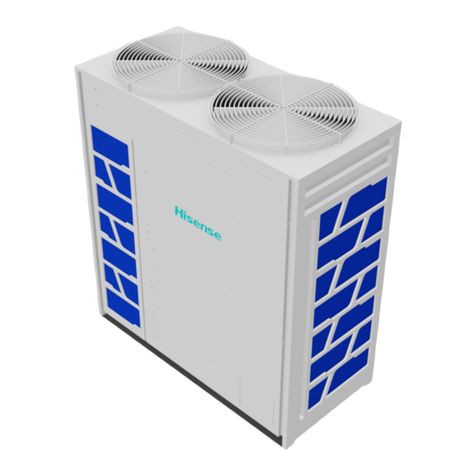
  9. Hisense AVWT-76FESRA User manual

Hisense AVWT-76FESRA User manual

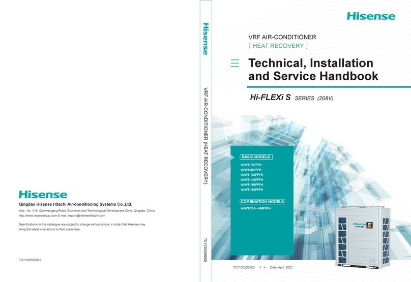
Hi-Flexi R Series Technical and Service Handbook TC1 2017007A
TC1 2017007ATC1 2017007A
Service Handbook
-Design-
-Installation-
-Service-
Technical and
AVWT-170~454FESZA
Inverter-Driven Multi-Split Central Air
Conditioning System
Hi-Efficiency R Series Outdoor Units
Models:
AVWT-76~96FESRA
AVWT-114~154FESSA
Specifications in this catalogue are subject to change without notice,in order that Hisense may bring the latest innovations to their customers.
Add: Hisense Information Industry Park 218,Qianwangang Road,
Qingdao Economic Development Zone,China
Tel:+86-532-80879968 Fax:+86-532-80875929
Http: //www.hisensehitachi.com
E-mail: [email protected]
Qingdao Hisense Hitachi Air-conditioning Systems Co.,Ltd.
IMPORTANT NOTICE AND SAFETY PRECAUTIONS
This manual gives a common description and information for this heat pump air conditioner which you
operate as well for other models.
This air conditioner has been designed for operating within a specific range mentioned in section 1.6.
●Hisense pursues a policy of continuing improvement in design and performance of products.
The right is therefore reserved to vary specifications without notice
●Hisense cannot anticipate every possible circumstance that might involve a potential hazard.
●This heat pump air conditioner is designed for standard air conditioning only. Do not use this heat pump
air conditioner for other purpose such as drying clothes, refrigerating foods or for any other cooling or
heating process.
●Do not install the unit in the following places. It may cause a fire, deformation, corrosion or failure
* Places where oil (including machinery oil).
* Places where a lot of sulfide gas drifts such as in hot spring
*
Places where inflammable as may generate or flow.
* Places where strong salty wind blows such as coast regions.
* Places with an atmosphere of acidity or alkalinity.
●Do not install the unit in the place where silicon gas drifts. If the silicon gas attaches to the surface of heat
exchanger, the fin surface repels wate . As a result, drain water splashes outside of the drain pan and
splashed water runs inside of electrical box. In the end, water leakage or electrical devices failure may
occur.
●Pay attention to the following points when the unit is installed in a hospital or other facilities where
electromagnetic wave generates from medical equipment.
* Do not install the unit in the place where the electromagnetic wave is directly radiated to the electrical
box, remote control cable or remote control switch.
* Install the unit at least 3 meters away from electromagnetic wave such as a radio.
●Do not install the unit in the place where the breeze directly catches the animals and plants. It could
adversely affect the animals and plants.
●The installer and system specialist shall secure against leakage according to local regulations or
standards. The following standards may be applicable, if local regulations are not available.
International Organization for Standardization, ISO5149 or European Standard, EN378 or Japan Standard,
KHKS0010.
●No part of this manual may be reproduced without written permission.
●It is assumed that this heat pump air conditioner will be operated and serviced by English speaking people.
If this is not the case, the customer should be add safety, caution and operating signs in the native
language.
●If you have any questions, contact your distributor or dealer of Hisense.
●
●
SAFETY SUMMARY
< Signal Words >
●Signal words are used to identify levels of hazard seriousness.
Definitions for identifying hazard levels are provided below with their respective signal words
: DANGER indicates a hazardous situation which, if not avoided,
will result in death or serious injury.
: WARNING indicates a hazardous situation which, if not avoided,
could result in death or serious injury.
: CAUTION, used with the safety alert symbol, indicates a hazardous situation which,
if not avoided, could result in minor or moderate injury.
: NOTICE is used to address practices not related to personal injury.
: NOTE is useful information for operation and/or maintenance.
DANGER
WARNING
CAUTION
NOTICE
NOTE
SAFETY SUMMARY
●Do not perform installation work, refrigerant piping work, drain pump, drain piping and electrical wiring
connection without referring to our installation manual. If the instructions are not followed, it may result in
a water leakage, electric shock or a re.
●Use the specied non-ammable refrigerant (R410A) to the outdoor unit in the refrigerant cycle.
Do not charge material other than R410A into the unit such as hydrocarbon refrigerants (propane or etc.),
oxygen, ammable gases (acetylene or etc.) or poisonous gases when installing, maintaining and moving.
These ammables are extremely dangerous and may cause an explosion, a re, and injury.
●Do not pour water into the indoor or outdoor unit. These products are equipped with electrical parts.
If poured, it will cause a serious electrical shock.
●Do not open the service cover or access panel for the indoor or outdoor units without turning OFF the main
power supply.
●Do not touch or adjust safety devices inside the indoor unit or outdoor units. If these devices are touched
or readjusted, it may cause a serious accident.
●Refrigerant leakage can cause difculty with breathing due to insufcient air. Turn OFF the main switch,
extinguish any naked ames and contact your service contractor, if refrigerant leakage occurs.
●Make sure that the refrigerant leakage test should be performed.
Refrigerant (Fluorocarbon) for this unit is incombustible, non-toxic and odorless.
However if the refrigerant is leaked and is contacted with re, toxic gas will generate.
Also because the uorocarbon is heavier than air, the oor surface will be lled with it, which could cause
suffocation.
●The installer and system specialist shall secure safety against refrigerant leakage according to local
regulations or standards.
●Use an ELB (Earth Leakage Breaker).
In the event of fault, there is danger of an electric shock or a re if it is not used.
●Do not install the outdoor unit where there is high level of oil mist, ammable gases, salty air or harmful
gases such as sulfur.
●For installation, rmly connect the refrigerant pipe before the compressor starts operating.
For maintenance, relocation and disposal, remove the refrigerant pipe after the compressor stops.
●Do not perform a short-circuit of the protection device such as a pressure switch when operating.
It may cause a re and explosion.
DANGER
SAFETY SUMMARY
●Do not step or put any material on the product.
●Do not put any foreign material on the unit or inside the unit.
●Provide a strong and correct foundation so that;
a. The outdoor unit is not on an incline.
b. Abnormal sound dose not occur.
c. The outdoor unit will not fall down due to a strong wind or earthquake.
WARNING
CAUTION
●Do not use any sprays such as insecticide, lacquer, hair spray or other ammable gases within
approximately one (1) meter from the system.
●If circuit breaker or fuse is often activated, stop the system and contact your service contractor.
●Check that the ground wire is securely connected. If the unit is not correctly grounded, it lead electric
shock. Do not connect the ground wiring to gas piping, water piping, lighting conductor or ground wiring
for telephone.
●Connect a fuse of specied capacity.
●Before performing any brazing work, check to ensure that there is no ammable material around.
When using refrigerant be sure to wear leather gloves to prevent cold injuries.
●Protect the wires, electrical parts, etc. from rats or other small animals.
If not protected, rats may gnaw at unprotected parts and which may lead to a re.
●Fix the cables securely. External forces on the terminals could lead to a re.
●Provide a sufciently strong foundation. If not, the unit may fall down and it may lead to injuries.
●Do not install the unit in a place where oil, vapor, organic solvent and corrosive gas (ammonia, sulfur
compound and acid) may be present in quantities.
It may cause refrigerant leakage due to corrosion, electrical shock, deteriorated performance and
breakage.
●Perform electrical work according to Installation Manual and all the relevant regulation and standards.
If the instructions are not followed, an electrical shock and re may occur due to insufcient capacity and
inadequate performance.
●Use specied cables between units and choose the cables correctly. If not, an electrical shock or re may
occur.
●Ensure that the wiring terminals are tightened securely with the specied torques. If not, generating re or
electrical shock at the terminal connection part may occur.
˗Do not install the indoor unit, outdoor unit, remote control switch and cable within approximately 3 meters
from strong electromagnetic wave radiators such as medical equipment.
˗Supply electrical power to the system to energize the oil heater for 12 hours before startup after a long
shutdown.
˗Make sure that the outdoor unit is not covered with snow or ice, before operation.
˗In some cases, the packaged air conditioner may not be operated normally under the following cases.
* In case that electrical power for the packaged air conditioner is supplied from the same power
transformer as the device*.
* In case that the power source wires for the device* and the packaged air conditioner are located close to
each other.
Device*: (Ex) Lift, container crane, rectifier for electric railway, inverter power device, arc furnace,
electric furnace, large-sized induction motor and large-sized switch.
It consumes a large quantity of electrical power.
Regarding the cases mentioned above, surge voltage may be inducted in the power supply wiring for the
packaged air conditioner due to a rapid change in power consumption of the device and an activation of
switch.
Therefore, check the field regulations and standards before performing electrical work in order to protect
the power supply for the packaged air conditioner.
˗It is recommended that the room will be ventilated every 3 to 4 hours.
˗The heating capacity of the heat pump unit is decreased according to the outdoor air temperature.
Therefore, it is recommended that auxiliary heating equipment be used in the field when the units
is installed in a low temperature region.
NOTICE
NOTE
˗Regarding transport / storage temperature within -25~55°C.
˗Correct Disposal of this product.
This marking indicates that this product should not be disposed with other household wastes.
To prevent possible harm to the environment or human health from uncontrolled waste disposal, recycle it
responsibly to promote the sustainable reuse of material resources. To return your used device, please use
the return and collection systems or contact the retailer where the product was purchased. They can take this
product for environmental safe recycling.
˗ All the operation method of remote control switch mention in this handbook is base on HYXE-J01H.
Turn to the operation manul accompanied with the remote control switch for detailed information of
other types.
- CONTENTS -
1. Connectable Outdoor Units and Working Range ......................................................... 1
1.1 Models of Outdoor Unit ............................................................................................ 1
1.2 Various Indoor Units and Combinations ................................................................... 2
1.3 Combination(Standard Type) .................................................................................... 3
1.4 Communication System ........................................................................................... 4
1.5 Piping System ........................................................................................................... 5
1.6 Operating Range ....................................................................................................... 5
2. General Data ................................................................................................................... 12
3. Dimensional Data ........................................................................................................... 19
3.1 Dimensional Data of Outdoor Unit ............................................................................ 19
3.2 Switch Box ................................................................................................................ 21
3.3 Structure ................................................................................................................... 28
4. Selection Data ................................................................................................................ 31
4.1 Service Space .......................................................................................................... 31
4.2 Capacity Characteristic Curve ................................................................................... 33
4.3 Capacity Table Under Different Temperature(KW) ................................................... 40
4.4 Capacity Table Under Different Temperature(KW) ................................................... 45
4.5 Capacity Correction Based On Refrigerant Piping Length ........................................ 51
4.6 Correction Factor According to Defrosting Operation .............................................. 53
4.7 Electrical Data ............................................................................................................ 54
4.8 Sound Data ................................................................................................................ 55
5. Component Data ........................................................................................................... 61
6. Control System ............................................................................................................... 65
6.1 Refrigerantion Cycle ................................................................................................. 65
6.2 Function Control Unit ............................................................................................... 68
6.3 Function Selection, Input & Output, Safety and Protective Devices ........................ 69
6.4 Standard Operating Procedure Chart ....................................................................... 81
7. Structure ......................................................................................................................... 92
7.1 Outdoor Unit & Refrigerant Cycle ............................................................................ 92
7.2 Necessary Tools and Instrument List for Installation ............................................... 92
8. Unit Transportation and Handing .................................................................................... 94
8.1 Transportation ......................................................................................................... 94
8.2 Hanging Method ....................................................................................................... 95
9. Outdoor Installation ........................................................................................................ 96
9.1 Factory-Supplied Accessories ................................................................................ 96
9.2 Installation ................................................................................................................ 97
9.3 Maintenance Space ................................................................................................... 97
9.4 Foundation ................................................................................................................ 98
9.5 Treatment of Condensed Water .............................................................................. 100
10. Refrigerant Piping Work ............................................................................................... 101
10.1 Piping Materials ...................................................................................................... 101
10.2 Flare and Connector .............................................................................................. 104
10.3 Caution about outdoor unit Installation ................................................................... 105
10.4 Piping Connection .................................................................................................. 107
11. Electrical wiring ............................................................................................................ 117
11.1 General Inspection ................................................................................................. 117
11.2 Wiring .................................................................................................................... 118
11.3 Electrical Wiring for Outdoor Unit ......................................................................... 120
11.4 Electrical Wiring Connection of Indoor Unit, Outdoor Unit and Switch Box .......... 122
12. Additional Refrigerant Charge ...................................................................................... 124
12.1 Air-Tight Test ......................................................................................................... 124
12.2 Vacuuming .............................................................................................................. 126
12.3 Additional Refrigerant Charge Calculation .............................................................. 127
12.4 Charging Work ........................................................................................................ 128
12.5 Automatic Simple Judgement System for Refrigerant Amount ............................ 129
12.6 Consideration ........................................................................................................ 130
13. Setting of DIP Switches ............................................................................................... 131
13.1 Function of RSW, DSWs and LEDs ....................................................................... 131
13.2 Function of RSW、DSW、LED .............................................................................. 133
13.3 Procedure of Checking Each Main Parts .............................................................. 134
13.4 Procedure of Checking Other Main Parts ............................................................. 135
13.5 Communication Settings ....................................................................................... 140
14. Test Run ....................................................................................................................... 141
14.1 Before Test Run ................................................................................................... 141
14.2 Test Run By Wired Controller ................................................................................ 142
14.3 Trial Operation via Outdoor Unit ............................................................................ 144
15. Check and troubleshooting .......................................................................................... 148
15.1 Overview of Inspection ......................................................................................... 148
15.2 Inspection Operations ........................................................................................... 151
15.3 Spot Inspection and Troubleshooting ................................................................... 152
15.4 Troubleshooting ..................................................................................................... 162
15.5 Trouble shooting in the detection mode ................................................................ 243
16. Appendix ...................................................................................................................... 260
1.1 Models of Outdoor Unit
Base Unit
Capacity (HP) Model 76 (8) Model 96 (10) Model 114 (12) Model 136 (14) Model 154 (16)
Models AVWT-76FESRA
Model 76~96
[Combined module]
Capacity (HP) Model 170 (18)Model 190(20)Model 212 (22)Model 232 (24)Model 250 (26)
Model AVWT-170FESZA AVWT-190FESZA AVWT-212FESZA AVWT-232FESZA AVWT-250FESZA
Comination
unit
AVWT-96* AVWT-114* AVWT-136* AVWT-114* AVWT-136*
AVWT-76* AVWT-76* AVWT-76* AVWT-114*AVWT-114*
-----
Capacity (HP) Model 272 (28)Model 290(30)Model 308 (32)Model 324 (34)Model 340 (36)
Model AVWT-272FESZA AVWT-290FESZA AVWT-308FESZA AVWT-324FESZA AVWT-340FESZA
AVWT-136* AVWT-154* AVWT-154* AVWT-136* AVWT-154*
AVWT-136* AVWT-136*AVWT-154* AVWT-96* AVWT-96*
---
Capacity (HP) Model 364 (38)Model 382 (40)Model 398 (42)
Model AVWT-364FESZA AVWT-382FESZA AVWT-398FESZA
AVWT-154* AVWT-154* AVWT-154*
AVWT-114* AVWT-136* AVWT-154*
AVWT-96* AVWT-96*
AVWT-96FESRA AVWT-114FESSA AVWT-136FESSA AVWT-154FESSA
Comination
unit
Comination
unit
Model 114 ~154
AVWT-96*AVWT-96*
AVWT-96*
Model 420 (44) Model 438 (46)
AVWT-420FESZA AVWT-438FESZA
AVWT-154* AVWT-154*
AVWT-154* AVWT-154*
AVWT-154* AVWT-136*
Model 454 (48)
AVWT-454FESZA
AVWT-154*
AVWT-154*
AVWT-154*
Capacity (HP)
Model
Comination
unit
1. Connectable Outdoor Units and Working Range
--- - -
1
(Note) Outdoor unit of Models 170~454 consists of 2~3 base units in the combination pattern as given in the table
above, and any combination pattern other than specified in the table is unacceptable.
Model 170 Model 190~212 Model 232~308
Model 324~340 Model 364~398
Model 420~454
1.2 Various Indoor Units and Combinations
The line-up of new Hi-Flexi R series indoor units has been extended up to 104 indoor units in 12 types to meet various
building requirements.
: Available
Indoor Unit Type Nominal Capacity (kBtu/h)
07 09 12 14 17 18 22 24 27 30 38 48 54 76 96
Ceiling Ducted Type (Low Static Pressure)
Low-Height Ceiling Ducted Type
4-Way Cassette Type
Wall-Mounted Type
Floor-Concealed Type
Ceiling and Floor Type
Slim Ceiling Ducted Type
Compact 4-Way Cassette Type
Ceiling Ducted Type (High Static Pressure)
1-Way Cassette Type
2-Way Cassette Type
Low-Height Ceiling Ducted Type (DC)
2
13 8
16 10
19 10
23 16
26 16
26 16
33 18
36 20
40 26
43 26
47 32
50 32
53 32
56 32
Max. Number of
Connectable I.U.
Recommended
Number of
Connectable I.U.
Min. Capacity at
Individual Operation
( kBtu/h )
Able to Connect a Set of Outdoor Unit with up to 64Indoor Units
Utilizing an inverter control, a wide range of operation capacity control is also available. A maximum total
combination horsepower of 140% and a minimum total combination horsepower of 50% can be chosen by
combination of the indoor units when compared with the nominal outdoor unit capacity. Therefore, the new
system can meet individual air conditioning requirements in most office buildings
Model
Range of
Combination
Capacity
( kBtu/h )
07 50~140%
59 32
64 38
64 38
64 38
64 38
64 38
64 38
AVWT-76*
AVWT-96*
AVWT-114*
AVWT-136*
AVWT-154*
AVWT-170*
AVWT-190*
AVWT-212*
AVWT-232*
AVWT-250*
AVWT-268*
AVWT-287*
AVWT-306*
AVWT-324*
AVWT-340*
AVWT-364*
AVWT-382*
AVWT-398*
AVWT-420*
AVWT-438*
AVWT-454*
IMPORTANT:
1. In a system where all indoor units operate at the same time, total of these indoor units should not be larger than combined
capacity of the outdoor units, or otherwise overload may occur under severe working condition or within narrow operating range.
2.
3.
4. Compared to indoor unit of 12kBtu/h, those of 07kBtu/h and 09kBtu/h, if set to high-velocity airflow, may deliver airflow in too low
temperature, so prior to installation, check the operation environment and installation location with much care. Where the
equipment is installed at a location which may be subject to the circumstance as stated above, number of indoor units connected
may be smaller than the number recommended in the table above.
In a system where not all indoor units operate at the same time, total capacity of these indoor units can be up to 140% of
total capacity of the outdoor units.
If the system is applied in cold area (with ambient temperature below -10°C) or high heat load environment, the total capacity
of indoor units should be less than combined capacity of outdoor units and total length of pipeline shall be less than 300m.
1.3 Combination(Standard Type)
3
1.4 Communication System
1.5 Piping System
1.5.1 Selection of Piping System
※1. Manifold pipe #1 is the one close to indoor unit side
※2. Straight-line distance before main piping of manifold pipe should be more than 500mm.
※3. When manifold pipe following the First Branch is larger than the first branch pipe, re-size it to the same as the first branch
pipe. When pipe following the first branch pipe is larger than main pipe (2), re-size it to the same as the main pipe (2).
※4 If equivalent pipe length from manifold pipe #1 of outdoor unit to the nearest indoor unit is more than 100mm, gas and liquid
pipes of main pipe (2) (from manifold pipe #1 of outdoor unit to 1st branch pipe) must be larger by one number, and the 1st
branch pipe should be re-sized correspondingly.
Hisense Centralized Control System
Hisense centralized control system can realize centralized monitoring and control of all air conditioners through the
computer, the system has powerful functions and is simple to operate, a maximum of 2048 outdoor units and 4096
indoor units can be monitored and controlled by the system.
Hisense Smart Home Management System
Connection and normal communication can be realized between the air conditioning system and the smart home
system through the air conditioning network converter, by incorporating household central air-conditioning system and
hot water system into the smart home system, application management that is more humanized and more convenient
can be realized.
RJ45 Network
Outdoor Unit Indoor Unit
Building Management System Hi-Dom
Hisense Air Conditioner
Hi Net
L3
L2
H2
H1
L1
H5
L5
L3L3
A
(*6) (*6)
(*1)
Outdoor
Unit
Indoor
Unit
Indoor
Unit
Indoor
Unit
B
Outdoor
Unit C
Outdoor
Unit
Upstream Side
First
Branch
Manifold Pipe 1 Manifold Pipe 2
(*3)
44
L3L3
Indoor
Unit
Indoor
Unit
44
4
3
3
111
2
3
4
(1) Manifold pipe of outdoor unit
●Tube Specifications for AVWT-76*~AVWT-154* (basic modules)
(Φmm)
●
Gas Line Ref. Piping
Connection (Low Pressure)
Gas Line Ref. Piping
Connection (High Pressure)
Liquid Line Ref. Piping
Connection
(fmm)
*Perform the installation of the outdoor unit and piping connection according to the figure.
Refer to the table for the outdoor unit model, the manifold pipe model and the piping diameter.
Piping Size for AVWT-170FESZA to AVWT-308FESZA (2 Units Combination)
< Figure for AVWT-232FESZA >
To Indoor Units Manifold Pipe
abc
(Indoor Unit on Left Side) (Indoor Unit on Right Side)
Outdoor Unit A Outdoor Unit B Outdoor Unit B Outdoor Unit A
To Indoor Units
Manifold Pipe
a
b
c
Model 76 96 114 136 154
Piping
Size a
Low Pressure
Gas 19.05 22 2 25.4 25.4 28.6
High Pressure
Gas 15.88 19.05 22.2 22 2 22.2
Liquid 9.53 9.53 12.7 12.7 12.7
Model
Combination
Unit
Outdoor
Unit A
Outdoor
Unit B
Piping Connection Kit HFQ-M202F HFQ-M212F
Piping
Size
a
Low Pressure
Gas 28.6 28.6 28.6 31.75 31.75 31.75 31.75
High Pressure
Gas 22.2 25.4 25.4 25.4 28.6 28.6 28.6
Liquid 15.88 15.88 15.88 19.05 19.05 19.05 19.05
b
Low Pressure
Gas 5.42 5.42 5.42 5.42 5.42 8.62 8.62
High Pressure
Gas 22.2 22.2 22.2 22.2 22.222.222.2
Liquid 12.7 12.7 12.7 12.7 12.7 12.7 12.7
c
Low Pressure
Gas 19.05 19.05 25.4 25.4 25.4 28.6
High Pressure
Gas 15.88 15.88 .222 .222 22.2 22.2
Liquid 9.53 9.53 12.7 12.7 12.7 12.7
AVWT-170FESZA
AVWT-96FESRA
AVWT-76FESRA
AVWT-190FESZA
AVWT-76ES RA
AVWT-212FESZA
AVWT-76FES RA
AVWT-114FESSAAVWT-136FESSA
AVWT-232FESZA
AVWT-114FESSA
AVWT-114FESSA
AVWT-250FESZA
AVWT-114FES SA
AVWT-136FES SA
AVWT-272FESZA
AVWT-136FESSA
AVWT-136FES SA
AVWT-290FESZA
AVWT-136 FESSA
AVWT-154FESSA
AVWT-308FESZA
AVWT-154FES SA
AVWT-154FESSA
28.6
.22 2
15.88
22.2
19.05
9.53
19.05
15.88
9.53
5.42
22 2
12.7
5
Piping Size for AVWT-324FESZA to AVWT-454FESZA (Triple Units Combination)
(fmm)
* Perform the installation of the outdoor unit and piping connection according to the gure.
Refer to the table for the outdoor unit model, the manifold pipe model and the piping diameter.
< Figure for AVWT-364FESZA >
(Indoor Unit on Left Side) (Indoor Unit on Right Side)
Outdoor Unit A
To Indoor Units
Outdoor Unit B Outdoor Unit C
Manifold Pipe
1
Manifold Pipe
2
acde
b
Outdoor Unit A
To Indoor Units
Outdoor Unit C Outdoor Unit B
Manifold Pipe
2
Manifold Pipe
1
d
a
c
d
e
●
Model
Combination
Unit
Outdoor
Unit A
Outdoor
Unit B
Outdoor
Unit C
Piping Connection Kit HFQ-M302F
Piping
Size
a
Low Pressure
Gas 8.13 8.13 38.1 38.1 38.1 38.1
High Pressure
Gas 31.75 31.75 1.753 31.75 31.75 31.75
Liquid 19.05 19.05 19.05 19.05 19.05 19.05 19.05 19.05
b
Low Pressure
Gas 8.62 28.6 28.6 31.75 31.75 31.75 1.753
High Pressure
Gas 5.42 25.4 8.62 8.62 8.62
Liquid 15.88 15.88 15.88 19.05 19.05 19.05 19.05
c
Low Pressure
Gas 5.42 8.62 8.62 28.6 28.6 8.62 8.62 8.62
High Pressure
Gas .222 .222 .222 22.2 22.2 22.2 .222 .222
Liquid 12.7 12.7 12.7 12.7 12.7 12.7 12.7 12.7
d
Low Pressure
Gas 22.225.4 25.4 28.6 8.62 8.62 8.62
High Pressure
Gas 22.2 .222 22.2 .222 22.2 22.2
Liquid 9.53 12.7 12.7 12.7 12.7 12.7 12.7
e
Low Pressure
Gas 22.2 25.4 25.4 28.6
High Pressure
Gas 22.2 22.2 .222
Liquid 9.53 12.7 12.7 12.7
AVWT-136FESSA
AVWT-324FESZA
AVWT-96FESRA
AVWT-96FESRA
AVWT-154FESSA
AVWT-340FESZ A
AVWT-96FESRA
AVWT-154FESSA
AVWT-364FESZA
AVWT-114FESSA
AVWT-96FESRA
AVWT-154FESSA
AVWT-382FESZA
AVWT-136FESSA
AVWT-96 FESRA
AVWT-398FESZA
AVWT-154FESSA
AVWT-154 FESSA
AVWT-420FESZA
AVWT-154FESSA
AVWT-114FESSA
AVWT-1 54FESS A
AVWT-438FESZA
AVWT-154FESSA
AVWT-136FESSA
AVWT-154FESSA
AVWT-454FESZA
AVWT-154FESSA
AVWT-154FESSA
19.05
1.753
8.62
22.2
19.05
AVWT-96FESRA
1.753
28.6
22.2
22.2
9.53
22.2
9.53
19.05
19.05
8.62
5.42
15.88
22.2
9.53
19.05
AVWT-154FESSA
AVWT-96FESRA
22.2
9.53
19.05
22.2
9.53
19.05
HFQ-M212F
6
①Branch pipe after First Branch
②Termind Indoor Unit
Ą
Indoor Capacity(KW)Longest equivalent piping length<100m
Air pipe὇NNὈLiquid pipe὇NNὈ
0714Ą5
1718 Ą5
2254  
76 
96 
Ą5From 05~19 kBtu/h In door unit and wall mounted type 22 KBtu/h,longer the liquid
pipe size from 6.35 to 9.35,If the pipe lenghth longer than 15m。
● Branch Pipe (Optional Parts)
< Line Branch >
First Branch
Outdoor Unit (kBtu/h) Model
76 to 96 HFQ-M282F
114 to 154 HFQ-M452F
170 to 232 HFQ-M562F
250 to 340 HFQ-M692F
264 to 510 HFQ-M902F
Pipe Diameter and Branch Pipe after First Branch *
Total Indoor Unit
(kBtu/h)
Low
Pressure
Gas
High
Pressure
Gas
Liquid Model
(fmm) (fmm) (fmm)
Lower than 57 15.88 12.7 9.53 HFQ-M142F
57 to 86 19.05 15.88 9.53 HFQ-M282F
86 to 114 22.2 19.05 9.53
114 to 154 25.4 22.2 12.7 HFQ-M452F
154 to 170 28.6 22.2 12.7 HFQ-M562F
170 to 212 28.6 22.2 15.88
212 to 250 28.6 25.4 15.88 HFQ-M692F
250 to 340 31.75 28.6 19.05
Over 340 38.1 31.75 19.05 HFQ-M902F
*: If the piping branch at 2 pipes portion is necessary, use branch
pipe of
HFQ-102F, HFQ-162F, HFQ-242Ffor heat pump type.
7
< Manifold Pipe (Models: HFQ-M202F, HFQ-M212F, HFQ-M302F) > [ Installation Work ]
For Heat Recovery System
Model Low Pressure
Gas Line
High Pressure
Gas Line Liquid Line
Reducer for
Low Pressure
Gas Line
Reducer for
High Pressure
Gas Line
Reducer for
Liquid Line
HFQ-M202F
HFQ-M212F
HFQ-M302F
Unit: mm, ID: Inner Diameter, OD: Outer Diameter
ID 25.4
ID 28.6
ID 22.2
25.4
22.2
Ø
Ø
ID 19.05
ID 15.88
ID 12.7
ID 28.6
ID 25.4
Ø
22.2
ID 25.4
ID 28.6
ID 22.2
25.4
22.2
Ø
Ø
ID 19.05
ID 15.88
ID 12.7
ID 28.6
ID 25.4
Ø
22.2
ID 25.4
ID 28.6
ID 22.2
25.4
22.2
Ø
Ø
ID 19.05
ID 15.88
ID 12.7
ID 28.6
ID 25.4
Ø
22.2
ID 15.88 ID 15.88
ID 9.53
ID 12.7
ID 9.53
ID 6.35
Ø
25.4
Ø
19.05
Ø
19.05
ID 15.88
ID 12.7
ID 25.4
ID 22.2
ID 15.88
ID 12.7
OD 28.6
ID 19.05
ID 25.4
ID 22.2
ID 15.88
ID 12.7
OD 28.6
ID 19.05
ID 25.4
ID 22.2
ID 15.88
ID 12.7
OD 28.6
ID 19.05
ID 25.4
ID 22.2
ID 15.88
ID 12.7
OD 28.6
ID 19.05
ID 31.75
ID 38.1
ID 38.1
ID 32.0
ID 28.6
Ø
31.75
Ø
31.75
Ø
28.6
ID 31.75
ID 38.1
ID 38.1
ID 32.0
ID 28.6
Ø
31.75
Ø
31.75
Ø
28.6
ID 31.75
ID 38.1
ID 38.1
ID 32.0
ID 28.6
Ø
31.75
Ø
31.75
Ø
28.6
ID 22.2
ID 22.2
Ø
25.4
Ø
22.2
ID 19.05ID 19.05
ID 15.88
ID 15.88
ID 12.7
ID 12.7
ID 9.53
ID 9.53
ID 6.35
Ø
19.05
ID 22.2
ID 22.2
Ø
25.4
Ø
22.2
ID 19.05ID 19.05
ID 15.88
ID 15.88
ID 12.7
ID 12.7
ID 9.53
ID 9.53
ID 6.35
Ø
19.05
OD 31.75
ID 28.6 ID 25.4
ID 22.2
Q'ty: 1
OD 31.75
ID 28.6 ID 25.4
ID 22.2
Q'ty: 1
OD 31.75
ID 28.6 ID 25.4
ID 22.2
Q'ty: 1
Q'ty: 1
ID 25.4
ID 22.2
ID 15.88
ID 12.7
OD 28.6
ID 19.05
Q'ty: 1
ID 25.4
ID 22.2
ID 15.88
ID 12.7
OD 28.6
ID 19.05
Q'ty: 1
Q'ty: 1 Q'ty: 2
Q'ty: 1
OD 38.1
ID 34.92
Q'ty: 1
Piping shall be supported with adequate space.
Bent pipes and bypass piping (horizontal loop)
shall also be installed in order to absorb piping
elasticity caused by temperature changes.
■Piping Connection Size
Theendsofthebranchpipesarenishedas
showninthefollowinggures.Cuttheendof
the pipe to meet with the pipe size.
8
[ Installation Work ]
< Line Branch (Models: HFQ-M142F, HFQ-M282F, HFQ-M452F, HFQ-M562F, HFQ-M692F, HFQ-M902F >
ID15.88 ID15.88
ID15.88
ID15.88 ID15.88
ID15.88
ID15.88 ID15.88
ID15.88
ID15.88 ID15.88
ID15.88 ID15.88
ID15.88
ID15.88
ID15.88
ID15.88
ID15.88
ID15.88 ID15.88
ID15.88
ID15.88
ID12.7
ID12.7
ID12.7
ID12.7 ID12.7
ID12.7
ID12.7
ID12.7
ID12.7
ID12.7 ID12.7
ID12.7 ID12.7
ID12.7
ID12.7
ID12.7
ID12.7
ID12.7
ID12.7
ID12.7
ID12.7 ID12.7
ID19.05
ID19.05
ID19.05
ID19.05
ID19.05
ID19.05
ID19.05 ID19.05
ID19.05 ID19.05
ID19.05
ID19.05 ID19.05
ID19.05 ID19.05
ID19.05
ID22.2
ID22.2
ID22.2
ID22.2
ID22.2
ID22.2
ID22.2 ID22.2
ID22.2 ID22.2
ID22.2
ID22.2
ID22.2
ID22.2
ID22.2
ID22.2
ID22.2
ID9.53
ID9.53
ID9.53 ID9.53
ID9.53
ID9.53
ID9.53
ID9.53
ID9.53
ID9.53
ID9.53
ID12.7
ID9.53
ID9.53
ID9.53
ID9.53
ID9.53
ID9.53
ID9.53
ID9.53
ID6.35
ID6.35
ID6.35
ID6.35
ID6.35
ID6.35
ID6.35
ID12.7
OD6.35
OD6.35
OD6.35
OD6.35
OD6.35
OD6.35
ID25.4
ID25.4
ID25.4
ID25.4
ID25.4
ID25.4
ID25.4
ID25.4
ID25.4
ID25.4
ID25.4
ID25.4
Ø25.4
Ø25.4 Ø25.4
Ø25.4 Ø25.4
Ø25.4 Ø25.4
Ø25.4
Ø25.4
Ø22.2
Ø22.2 Ø22.2
Ø22.2
Ø22.2
Ø22.2
Ø22.2
Ø22.2
Ø22.2 Ø22.2
Ø22.2
Ø25.4
Ø22.2
Ø22.2
Ø22.2
Ø22.2
Ø19.05
Ø19.05 Ø19.05
Ø19.05
Ø19.05
Ø19.05
Ø25.4
Ø19.05
Ø12.7 Ø12.7
Ø12.7
Ø9.53
Ø9.53
Ø9.53
Ø9.53
ID9.53 ID9.53
ID9.53
ID6.35
ID6.35
Ø12.7 Ø9.53
Ø9.53
Ø9.53
Ø 9.53
ID28.6
ID28.6 ID28.6
ID28.6
ID28.6
ID28.6
ID28.6
ID28.6
ID28.6
ID28.6
Ø28.6
Ø28.6
Ø28.6
ID28.6
ID31.75
ID31.75 ID31.75
ID38.1
ID38.1
ID38.1 ID38.1
ID38.1
ID38.1
ID32.0
ID32.0 ID32.0
Ø31.75
Ø31.75 Ø31.75
Ø31.75
Ø31.75
Ø31.75
OD28.6
ID15.88
ID19.05
ID22.2
ID12.7
ID25.4
OD28.6
OD31.75
HFQ-M142F
HFQ-M282F
HFQ-M452F
HFQ-M562F
HFQ-M692F
HFQ-M902F
Model Low Pressure
Gas Line
High Pressure
Gas Line Liquid Line
Reducer for
Low Pressure
Gas Line
Reducer for
High Pressure
Gas Line
Reducer for
Liquid Line
OD28.6
ID31.75 ID34.92
OD38.1
ID28.6
ID28.6 ID28.6
Q'ty:1 Q'ty:1
Q'ty:1
Q'ty:1
Q'ty: 2
ID15.88
ID19.05
ID22.2
ID12.7
ID25.4
OD28.6
ID15.88
ID19.05
ID22.2
ID12.7
ID25.4
OD28.6
Q'ty:1
Q'ty:1 Q'ty:1
Q'ty: 2
ID15.88
ID19.05
ID22.2
ID12.7
ID25.4
OD28.6
ID15.88
ID19.05
ID22.2
ID12.7
ID25.4
OD28.6
Q'ty:1 Q'ty:1
ID15.88
ID19.05
ID22.2
ID12.7
ID25.4
OD28.6
ID15.88
ID19.05
ID22.2
ID12.7
ID25.4
OD28.6
Q'ty: 2
Q'ty: 2
Q'ty: 1
ID22.2
ID25.4
ID28.6
OD31.75
Q'ty: 1
ID22.2
ID25.4
ID28.6
OD31.75
Q'ty: 1
Q'ty: 1
Q'ty: 1
Q'ty: 1
Unit: mm, ID: Inner Diameter, OD: Outer Diameter
9
1 Pipe Diameter for Outdoor Unit
2 Main Pipe Diameter
(Base Unit or Piping Connection Kit 1 to First Branch)
[Branch pipe of First Branch] (3 Pipes) (*2)
Outdoor Unit Low
Pressure
Gas
High
Pressure
Gas
Liquid
76 19.05 15.88 9.53
96 22.219.05 9.53
114 and 136 25.4 22.212.7
154 28.6 22.212.7
170 and 190 28.6 22.215.88
12 and 2322 28.6 25.4 15.88
502 31.75 25.4 19.05
27272272 31.75 28.6 19.05
364 to 454 38.1 31.75 19.05
3 [Pipe Diameter after First Branch] (3 Pipes) (*3)(*7)
Total Indoor Unit Low
Pressure
Gas
High
Pressure
Gas
Liquid
15.88 12.7 9.53
19.05 15.88 9.53
22.219.05 9.53
25.4 22.212.7
28.6 22.212.7
28.6 22.215.88
28.6 25.4 15.88
31.75 28.6 19.05
38.1 31.75 19.05
6 [Pipe Diameter between Branch pipe and Indoor Unit]
(2 Pipes) (*4)
Indoor Unit
kBtu/h Gas Liquid
07 to 14 12.7 6.35 (*5)
15.88 6.35 (*5)
to 5422 15.88 9.53
76 19.05 9.53
96 22.2 9.53
● Piping Size (fmm)
5 [Pipe Diameter for 2 Pipes and Branch pipe]
Total Indoor Unit
kBtu/h Gas Liquid
Lower than 57 15.88 9.53
57 to 86 19.05 9.53
86 to 114 22.29.53
114 to 154 25.4 12.7
154 to 170 28.6 12.7
170 to 250 28.6 15.88
4 [Pipe Diameter between Switch Box to Branch pipe] (3 Pipes and 2 Pipes) (*9)
Switch Box Model
Max.
Combination
of Indoor Unit
(*8)
Available Combination
of Indoor Unit
Capacity (kBtu/h)
(*10), (*11)
3 Pipes 2 Pipes
Low Pressure
Gas
High Pressure
Gas Gas Liquid
HCH-160D 7
07 to 14 15.88 12.7 12.7 (*15) 9.53
15 to 38 15.88 12.7 15.88 9.53
9 to 573 19.05 15.88 15.88 9.53
HCH-280D 858 to 76 19.05 15.88 19.05 9.53
77 to 96 22.219.05 22.29.53
a
H4
b
L3
Switch Box
L4
c
H3
L5
d e
L3
L3
F
L3 L2
H2
H1
L1
H5
A
(*6) (*6) (*1)
(*3)
(*12)
Outdoor
Unit
Indoor
Unit
Indoor
Unit Indoor
Unit
Indoor
Unit
Indoor
Unit Indoor
Unit Indoor
Unit
B
Outdoor
Unit C
Outdoor
Unit
Upstream Side
First
Branch
Piping
Connection Kit 1 Piping
Connection Kit 2
(Exclusive Use of
Cooling Operation)
: 3 Pipes Portion
(High Pressure Gas Pipe, Low Pressure Gas Pipe, Liquid Pipe)
: 2 Pipes Portion
(Gas Pipe, Liquid Pipe)
: 2 Pipes Portion
(Low Pressure Gas Pipe, Liquid Pipe)
4 4 4
6 6 6
33
3
111
2
6 6 6
6
5
44
17 to 18
Switch Box Switch Box
Switch Box
Lower than 57
57 to 86
86 to 114
114 to 154
154 to 170
170 to 212
21221212
50 to 3402
Over 340
kBtu/h
kBtu/h
to 340
to 250
10
Item Mark
Allowable Piping Length (*13)
< the recommended
connectable number
of Indoor Unit
> the recommended
connectable number
of Indoor Unit
Total Piping Length Total Liquid Piping
Actual Length < 1,000m (*14) < 300m
Maximum Piping Length Actual Length L1 < 165m < 165m
Equivalent Length < 190m < 190m
L2< 90m < 40m
Maximum Piping Length between
Branch pipe of 1st Branch and Each Indoor Unit
Maximum Piping Length between
Each Branch pipe and Each Indoor Unit L3< 40m < 30m
Total Piping Length between
Switch Box and Each Indoor Unit
* L4
* a+b+c+d+e
HCH-160D: < 30m HCH-160D: < 30m
HCH-280D: < 10m HCH-280D: < 10m
Piping Length between Piping Connection Kit 1 and
Each Outdoor Unit L5 < 10m < 10m
Height Difference between
Outdoor Units and Indoor Units
O.U. is Higher H1 < 50m < 50m
O.U. is Lower < 40m < 40m
Height Difference between Indoor Units H2< 15m < 15m
Height Difference between H3< 4m < 4m
H4 < 15m < 15m
Indoor Units using the Same Switch Box
Height Difference between Switch Box
Height Difference between Outdoor Units H5 < 0.1m < 0.1m
NOTES:
1. Check the gas pipe and liquid pipe are equivalent in terms of the piping length and piping system.
2. Use a branch pipe (system components) for the branch pipe of indoor unit and Switch Box.
3. Install the outdoor unit, branch pipe and Switch Box according to each “Installation & Maintenance Manual”.
4. If the piping length (L3) between each branch pipe and each indoor unit is considerably longer than other indoor unit,
refrigerant may not flow well and also performance may be deteriorated compared to other models
(Recommended Piping Length: within 15m)
(*1): The piping connection kit is counted from the indoor unit side (as Piping Connection Kit 1).
(*2): When the maximum length of the equivalent refrigerant pipe (L1) from the outdoor unit/piping connection kit 1 to the
indoor unit is over 100m, the pipe size of gas/liquid line from the outdoor unit/piping connection kit 1 to first branch
should be increased with the reducer (field-supplied)
(*3): If the refrigerant piping length is more than 100m, no need to increase the pipe size after first branch.
If the branch pipe size is larger than the first branch, adjust the branch pipe size to the first branch. In case that the
selected pipe size after the first branch is larger than the pipe size before the first branch, use the same pipe size
as before the branch.
(*4): The pipe diameter 6 should be the same as the indoor unit piping connection size.
(*5): When the liquid piping length is longer than 15m, use f9.53 pipe and reducer (field-supplied)
(*6): Keep the direct distance of 500mm or more after the piping connection kit.
(*7): In case of the line branch, if the length of the pipe between the terminal
branch of 3 pipes (specified in the figure of mark F) and the farthes
indoor unit exceeds 5m, use a T-branch to the applicable liquid pipe of
3 branches. (Corresponding to the Same Diameter as JIS B8607)
(*8): In case that the number of connectable indoor unit exceeds four, the high/low pressure gas pipe, gas pipe and
liquid pipe (Fig. 4 5 6 ) need to increase one size respectively.
(*9): The liquid pipe is not required to connect to the Switch Box. Refer to Table 6 for the liquid pipe diameter between
multi-kit and indoor unit.
(*10): In case that the combination of indoor unit capacity is 96kBtu/h for HCH-280D, the performance may decrease
approximate 5% in cooling and 10% in heating.
(*11): The excess of the total capacity may cause insufficient p rformance and abnormal sound. Be sure to connect
within the allowable total capacity.
(*12): For the exclusive cooling operation, connect indoor units with low pressure gas pipe and liquid pipe (without Switch
Box). The total capacity of the exclusive cooling operation should be smaller than 50% of the total indoor unit
capacity.
(*13): The condition of refrigerant piping installation is different depending on the connected indoor unit quantities.
(*14): Allowable total piping length may become shorter than 1,000m due to the limitation of maximum additional
refrigerant amount.
(*15): In case that a branch is located downstream of the Switch Box and also the connected indoor unit capacity is
7~14kBtu/h use f15.88 for the gas pipe.
● Piping Work Conditions (Refer to the figure of previous age.)
Upstream
Upstream
Installation of Liquid T-Branch
11
Operation temperature range Follow the table below.
Power Supply
Working Voltage: 90% to 110% of the Rated Voltage Working Frequency: ±1% of the Rated Frequency Voltage
Imbalance: Within a 3% Deviation from Each Voltage at the Main Terminal of Outdoor Unit
Starting Voltage: Higher than 85% of the Rated Voltage
1.6 Operating Range
Heating Operation
Indoor
Temperature
Minimum 15oC DB
Maximum
Cooling Operation
21oC DB / 15oC WB
32oC DB / 23oC WB
Outdoor
Temperature
Minimum
27oC DB
-20oC WB (**)
Maximum
-5oC DB (*)
43oC DB 15oC WB
DB: Dry Bulb, WB: Wet Bulb
NOTES:
(*) 10oC DB ~ -5oC DB, Operation Control Range
(**) -12oC WB ~ -20oC WB, Operation Control Range
Piping Length between
Branch pipe(First Branch)
and Each Indoor Unit (L2)
Main Piping Branch * Indoor Unit
Capacity Ratio
After Main Branch
Piping Length
After Branch
Number of Main
Piping Branch
< 40m
a+b+c < 30m
or
d+e+f < 30m
without Limit
-
a+b+c > 30m
and
d+e+f > 30m
within 2
within 41m to 90m - within 1 (Fig.1) > 40% (Fig.2)
NOTE:
* Main Piping Branch: Distribution from One (1) Branch pipe to Two (2) Branch pipes
The number of main piping branch depends on the piping length after branch (a to f).
● Piping Branch Restriction
Follow the table below when performing the field-supplied piping work.
First Main Branch
Second Main Branch
Within 41 ~ 90m Within 41 ~ 90m
First Main Branch
Indoor Unit Capacity Ratio
20%
Indoor Unit Capacity Ratio
80%
Main piping branches are 2 portions. Indoor unit capacity ratio is less than 40%.
Fig. 1 Fig. 2
de
f
ab
c
Indoor
Unit
Indoor
Unit
Indoor
Unit
Indoor
Unit
Main Piping Branch
12

This manual suits for next models

20

Other Hisense Air Conditioner manuals

Hisense ADM-24UX4SGKA User manual

Hisense

Hisense ADM-24UX4SGKA User manual

Hisense AS-07HR4SYDDEB5 User manual

Hisense

Hisense AS-07HR4SYDDEB5 User manual

Hisense AVW-38UCSC Instruction Manual

Hisense

Hisense AVW-38UCSC Instruction Manual

Hisense AP-10CR1SEJS User manual

Hisense

Hisense AP-10CR1SEJS User manual

Hisense AVWW-76UE(8)SB User manual

Hisense

Hisense AVWW-76UE(8)SB User manual

Hisense AP0819CR1W Technical manual

Hisense

Hisense AP0819CR1W Technical manual

Hisense AP1019CW1G Technical manual

Hisense

Hisense AP1019CW1G Technical manual

Hisense AMS-07UR4SNZA3 User manual

Hisense

Hisense AMS-07UR4SNZA3 User manual

Hisense AP1222CW1W Technical manual

Hisense

Hisense AP1222CW1W Technical manual

Hisense AVD-07UX2SAL Manual

Hisense

Hisense AVD-07UX2SAL Manual

Hisense AST-09UW4RVETG00A User manual

Hisense

Hisense AST-09UW4RVETG00A User manual

Hisense AMW2-18U4RJC Operating manual

Hisense

Hisense AMW2-18U4RJC Operating manual

Hisense AVWW-28UCSA Instruction Manual

Hisense

Hisense AVWW-28UCSA Instruction Manual

Hisense Hi-FLEXi S Series Instruction Manual

Hisense

Hisense Hi-FLEXi S Series Instruction Manual

Hisense KFR-3208GW Parts list manual

Hisense

Hisense KFR-3208GW Parts list manual

Hisense 7K Technical manual

Hisense

Hisense 7K Technical manual

Hisense AUC-18UX4SGAA Manual

Hisense

Hisense AUC-18UX4SGAA Manual

Hisense AVE-07UX2SAL Instruction Manual

Hisense

Hisense AVE-07UX2SAL Instruction Manual

Hisense AVH-09UXCSAA Instruction Manual

Hisense

Hisense AVH-09UXCSAA Instruction Manual

Hisense AUD-24UX4SZLH Operating manual

Hisense

Hisense AUD-24UX4SZLH Operating manual

Hisense HAWV9KR Technical manual

Hisense

Hisense HAWV9KR Technical manual

Hisense AS-07HR4SYDDEB User manual

Hisense

Hisense AS-07HR4SYDDEB User manual

Hisense 12K Guide

Hisense

Hisense 12K Guide

Hisense AP0522CR1W Technical manual

Hisense

Hisense AP0522CR1W Technical manual

Popular Air Conditioner manuals by other brands

Soleus Air GB-PAC-08E4 operating instructions

Soleus Air

Soleus Air GB-PAC-08E4 operating instructions

AHRI SUPERIOR Series Installation, operation & service manual

AHRI

AHRI SUPERIOR Series Installation, operation & service manual

Mitsubishi Electric MS-GK36VAT operating instructions

Mitsubishi Electric

Mitsubishi Electric MS-GK36VAT operating instructions

Thermal CS011126 User's & technical manual

Thermal

Thermal CS011126 User's & technical manual

Mitsubishi Electric PLA-SP BA Series Operation manual

Mitsubishi Electric

Mitsubishi Electric PLA-SP BA Series Operation manual

Hitachi RAK-18PSPA installation manual

Hitachi

Hitachi RAK-18PSPA installation manual

hawa 3122 Series operating instructions

hawa

hawa 3122 Series operating instructions

DeLonghi EX Series Instructions for use

DeLonghi

DeLonghi EX Series Instructions for use

Fujitsu AS*G09KXCA Series Service instruction

Fujitsu

Fujitsu AS*G09KXCA Series Service instruction

Frigidaire FAS155K1A1 Factory parts catalog

Frigidaire

Frigidaire FAS155K1A1 Factory parts catalog

Toshiba RAV-RM561KRTP-E installation manual

Toshiba

Toshiba RAV-RM561KRTP-E installation manual

GREE ELECTRIC GWH09TA-S3DNA1C Service manual

GREE ELECTRIC

GREE ELECTRIC GWH09TA-S3DNA1C Service manual

Arcoaire R4A3 installation instructions

Arcoaire

Arcoaire R4A3 installation instructions

Roller DHN 401 N EC Mounting instructions

Roller

Roller DHN 401 N EC Mounting instructions

Fortress Technologies FWAC08M16 user manual

Fortress Technologies

Fortress Technologies FWAC08M16 user manual

Crosley CAE10MR410A13 use & care

Crosley

Crosley CAE10MR410A13 use & care

Lennox LIFHC012021T431E-1 owner's manual

Lennox

Lennox LIFHC012021T431E-1 owner's manual

Haier HSU-09C03 Operation manual

Haier

Haier HSU-09C03 Operation manual

manuals.online logo
manuals.online logoBrands
  • About & Mission
  • Contact us
  • Privacy Policy
  • Terms and Conditions

Copyright 2025 Manuals.Online. All Rights Reserved.