HIT FITNESS G5 User manual

HIT00636
G5 INDOOR CYCLING BIKE
USER MANUAL

CAUTION:
MAX USER WEIGHT: 120KG
BEFORE USING THIS EQUIPMENT, CAREFULLY FOLLOW THE
INSTRUCTIONS AND READ ALL OF THE PRECAUTIONS LISTED, THEN
RETAIN THIS USER MANUAL FOR FUTURE REFERENCE.
Note: Please read this product manual carefully before installing or using our products

1
SAFETY INFORMATION
WARNING
TO REDUCE THE RISK OF SERIOUS INJURY, READ THE FOLLOWING SAFETY INSTRUCTIONS BEFORE
USING THE EQUIPMENT.
IMPORTANT: THIS UNIT IS INTENDED FOR HOME USE ONLY
1. It is important to read this entire manual before assembling and using the equipment. Safe and
efficient use can only be achieved if the equipment is assembled, maintained and used
properly. It is your responsibility to ensure that all users of the equipment are informed of all
warnings and precautions.
2. Before starting any exercise program you should consult your doctor to determine if you have
any physical or health conditions that could be a risk to your health and safety, or prevent you
from using the equipment properly. Please check with your doctor that this equipment is safe
to use if you are taking medication that affects your heart rate, blood pressure or cholesterol
level.
3. Listen to your body. Incorrect or excessive exercise can damage your health.
Stop exercising if you experience any of the following symptoms: Pain, tightness in your chest,
irregular heartbeat, extreme shortness of breath, feeling light headed, dizzy or nauseous. If you
do experience any of these conditions, you should consult your doctor before continuing with
your exercise program.
4. Keep children and pets away from the equipment. The equipment is designed for adult use
only.
5. Use the equipment on a solid, flat, level surface with a protective cover on your floor or carpet
to prevent damaging the surface. For safety, the equipment should have at least 0.6 metres of
free space all around it.
6. Before using the equipment, check that all nuts and bolts are securely tightened.
7. The safety level of the equipment can only be maintained if it is regularly examined for
damage and/or wear and tear.
8. Always use the equipment as indicated. If you find any defective components whilst
assembling or checking the equipment, or if you hear any unusual noise coming from the
equipment during use, stop. Do not use the equipment until the problem has been fixed.
9. Wear suitable clothing whilst using the equipment. Avoid wearing loose clothing which may
get caught in the equipment or that may restrict or prevent movement.
10. The equipment has been tested and certified to EN ISO 20957-1; EN ISO 20957-5 under
class H.C. Suitable for domestic, home use only. Maximum weight of user 120kg.
11. Care must be taken when lifting or moving the equipment so as not to injure your back.
Always use proper lifting techniques and/or use assistance.

2
EXPLODED DIAGRAM
16
3
17
18
14
13
15
19
4
7
8
25
24
16
2
12
17
18
1
14
5
6
10
9
11
21
20
23
22

3
PARTS LIST
NO.
NAME
SIZE
QTY.
NO.
NAME
SIZE
QTY.
1
Main Body
Assembly
1
15
Adjusting nut
M10
1
2
Front Stabilizer
Assembly
1
16
Carriage Bolts
M8X50
4
3
Rear Stabilizer
Assembly
1
17
Flat washer
Ø8.5
4
4
Saddle Post
Assembly
1
18
Cover nut
M8
4
5
Handle Post
Assembly
1
19
Flat washer
Ø10.5
1
6
Handle Frame
Assembly
1
20
Button head bolt
M8X16
4
7
Saddle Adjustment Frame
Assembly
1
21
Spring washer
Ø8.5
4
8
Saddle
Spring loaded
1
22
Pulse Wire
1
9
Monitor
Square
1
23
Signal Wire
1
10
Monitor Holder
fit for Ø25tube
1
24
Open wrench
13-15
1
11
Mobile phone holder
fit for Ø25tube
1
25
Inner hexagon spanner
6mm
1
12
Right pedal
R
1
13
Left pedal
L
1
14
Adjusting knob
M16
2
4
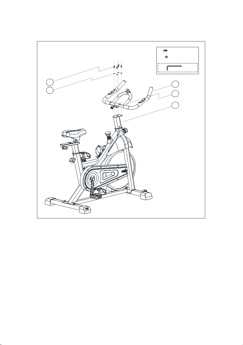
ASSEMBLY INSTRUCTIONS
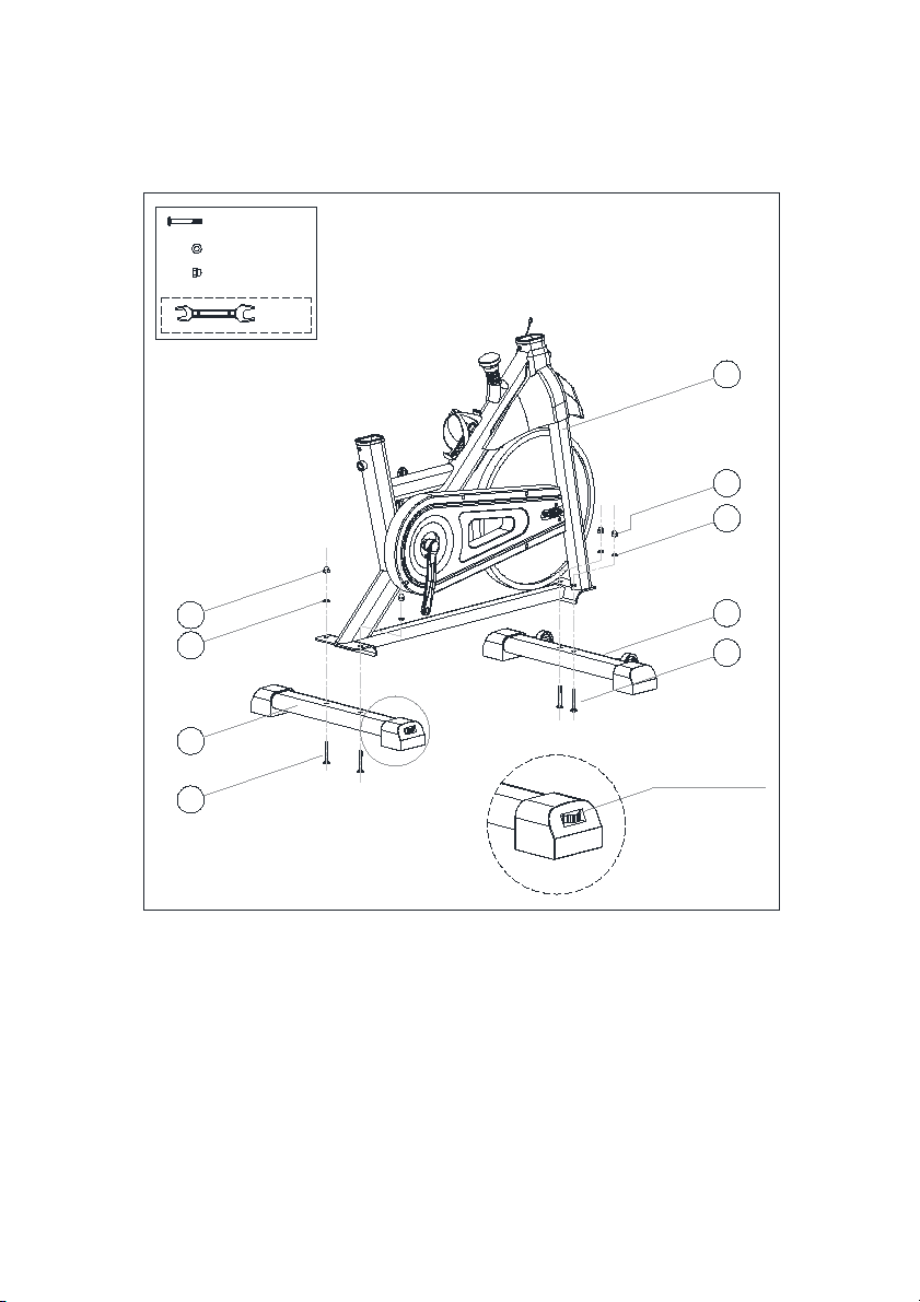
STEP 1
16
3
17
18
16
2
17
18
1
24#
18# 4psc
17# 4psc
16# 4psc
Foot adjusters
The Front Stabilizer (2) is fixed on the Main Body (1) with Carriage Bolts (16), Flat washers
(17) and cover nuts (18), and fixed with the open wrench (25). Note: the wheels that can be used
for transportation on the Front Stabilizer (2) are facing forward, as shown.
Similarly, the Rear Stabilizer (3) is fixed on the Main Body (1) with carriage Bolts (16), flat
washers (17) and cover nuts (18) and fixed with the open wrench (25).
Attention: The foot adjusters on the rear stabilizer (3) can adjust the machine to the ground
smoothly. The moving wheels on both sides of The Front Stabilizer (2) can move the machine a
short distance.
5
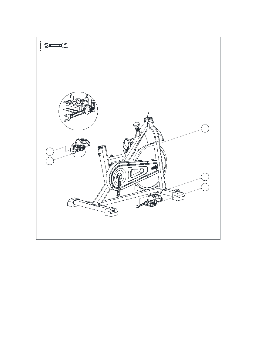
STEP 2
13
24
12
24
24#
1
Install the right pedal (12) with the R mark displayed onto The Main Body (1) and fix it with
an open wrench (24). Note: tighten it clockwise.
Similarly, Install the left pedal (13) with the L mark displayed onto the Main Body (1) and fix
it with an open wrench (24). Note: tighten counterclockwise.
6
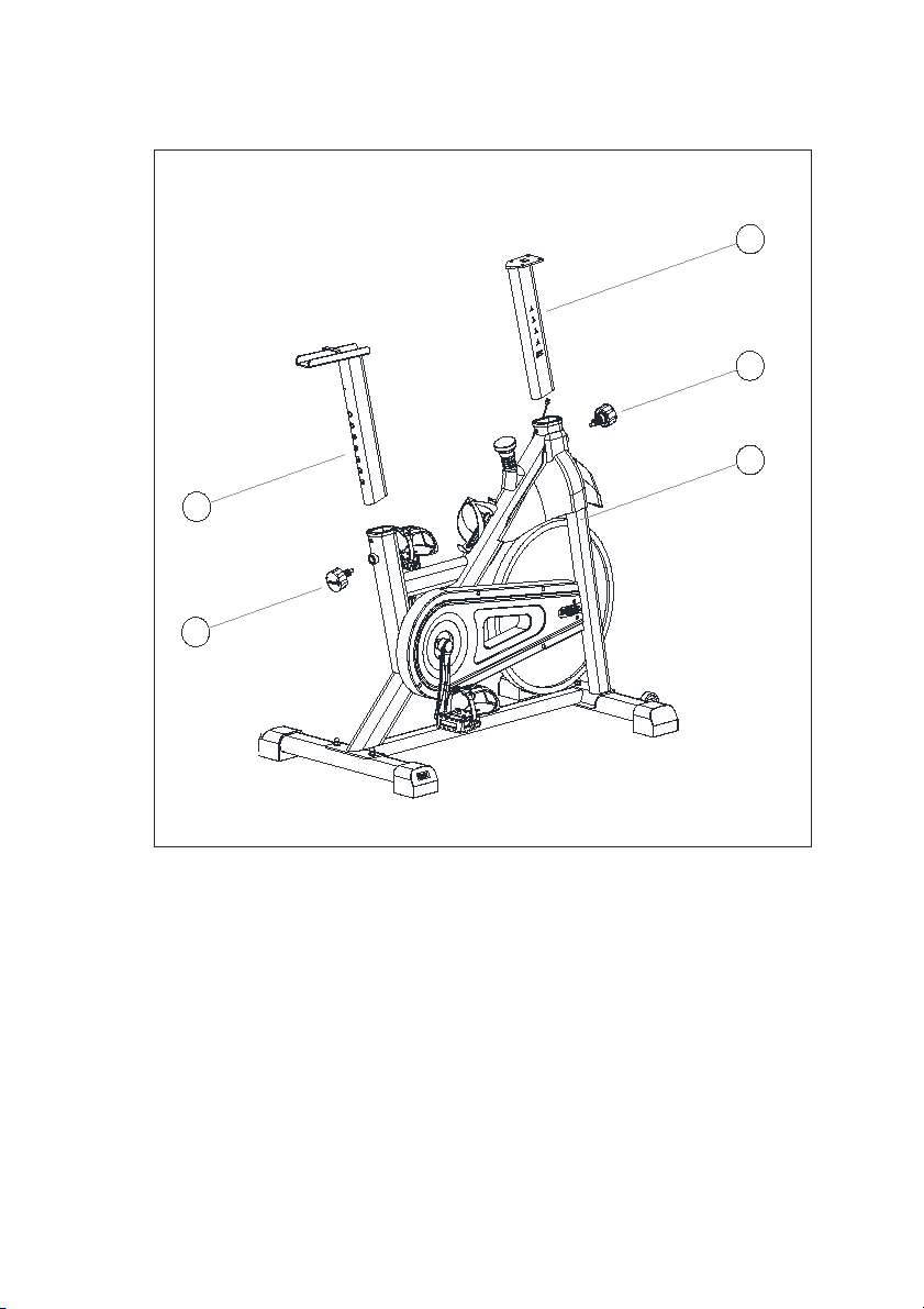
STEP 3
1
4
5
14
14
14
The Saddle Post (4) is inserted into the Main Body (1), and the Adjusting knob (14) is pulled
out so that the Adjusting knob (14) is automatically inserted into the corresponding hole of the
Saddle Post (4).
Similarly, the Handle Post (5) is inserted into the Main Body (1), and the Adjusting knob (14)
is pulled out so that the Adjusting knob (14) is automatically inserted into the corresponding hole
of the Handle Post (5).
The adjusting knobs (14) are installed in the front and back of the Main Body (1) respectively.
Note that no tightening is needed at this time.
7
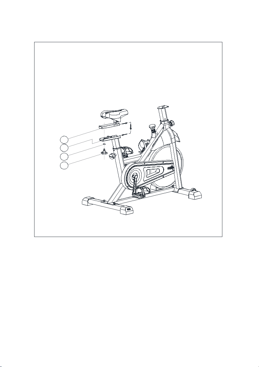
STEP 4
15
19
7
4
The seat adjustment frame (7) is installed on the seat post (4) and is fixed with a flat washer
(19) and an adjusting nut (15).
Note: Loosen the adjusting nut (15) to adjust the position of the seat adjusting frame (7) back
and forth to the corresponding position. The adjusting nut (15) needs to be tightened before use.
8
STEP 5
5
6
21
20 6
22
21# 4psc
20# 4psc
25#
The handle frame (6) is fixed on the handle post (5) with the spring washer (21) and the round
head bolt (20) and tightened with the Allen wrench (25).
9
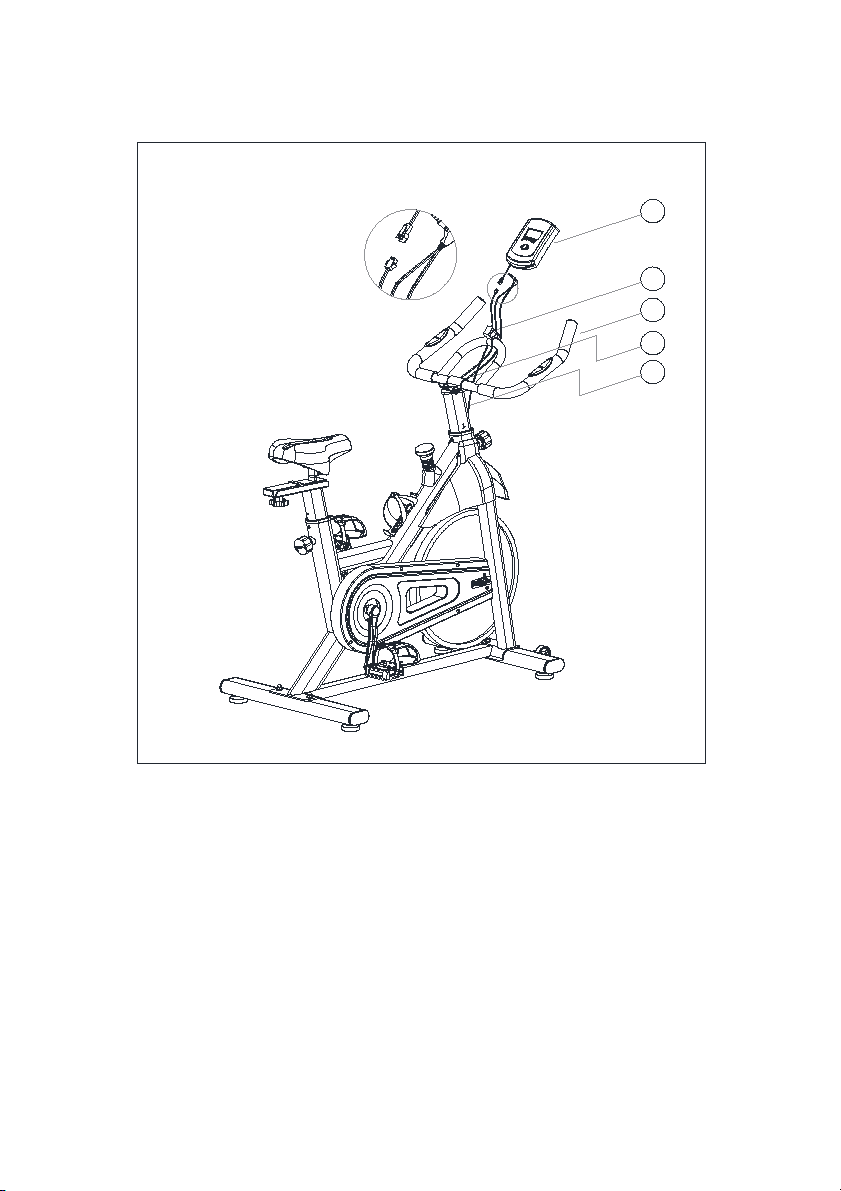
STEP 6
6
10
9
6
22
23
The Monitor Holder (10) is pulled and fixed on the Handle Frame (6) with the Self tapping
screw (24) and tightened with the inner hexagonal wrench (27).
The Monitor (9) is mounted on the Monitor Holder (10).
Insert the Pulse Wire(22) into the "pulse" hole on the back of the the Monitor (9).
Insert the Signal Wire (23) into the "sensor" hole on the back of the Monitor (9).

10
STEP 7
11
6
Install the Mobile phone holder (11) on the Handle Frame (6).
CAUTION: before using, please reconfirm that each part is tight and
firm, and the machine is stable.

11
COMPUTER FUNCTION
A, BATTERY INSTALLATION
Load two 1.5V AAA battery into the battery box on the back (after both batteries are installed, all
values will be "0")
B, FUNCTIONALLITY DESCRIPTION
1, automatic scanning (SCAN): open the screen or press the button to enter the SCAN state, all the
functions of the TIME-SPD-DIST-CAL-ODO-PUL will be automatically displayed on the main
screen.
2, the movement time (TIME): cumulative calculation of movement time from 00:00-99:59, the
user can press the button to select the time value display state.
3, the movement distance (DIST): cumulative calculation movement from the 0.0-999.9, the user
can press the button to select the value of the distance display.
4, calories (CAL): shows that the cumulative consumption of calories from 0.0-9999, the user can
press the button to select the value of the state of the display value. Note: this data is only a
rough description and cannot be used for medical treatment.
5, the speed of movement (SPEED): show the current speed of the athlete, the value of 0.0-999.9
km / mile / hour.
6, Odometer (ODO): the distance between motion and time is 0-9999 km.
7, Pulse (PUL): instant heart rate, 40-240 times / minute, Note: this data is only a rough
description and cannot be used for medical treatment.
8, reset: hold down the button for about 3 seconds, all the values will be returned to the "0", the
function can be reset.
C, ATTENTION
1, such as electronic display is not normal, the need to re install the battery to try again, the
battery,,+",can not be installed.
2, battery specification: 2 AAA 1.5V batteries
3, When the battery is dead, it must be removed from the electronic watch and handled safely.
12
TRAINING INSTRUCTIONS
IN ADDITION TO THE USE OF THIS EQUIPMENT, A REASONABLE DIET
SHOULD BE FOLLOWED TO MAINTAIN PHYSICAL FITNESS AND HEALTHY
MUSCLES.
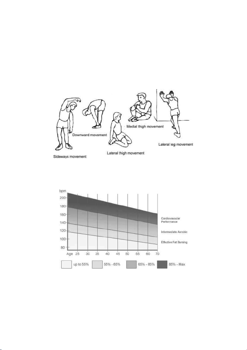
A, warm-up before training
This part of warming up can enhance the body’s blood circulation, and train the muscles, while
reducing the risk of cramps and muscle damage during training. Before and during each training
session please do warm-up exercises, some examples are shown in the diagram below, each
stretch is recommended to last for about 30 seconds.
B, training stage
This stage is the proper training phase, after a long period of use, your leg muscles will improve
flexibility. In the training process, the key is to do the training according to the training conditions,
and to choose the reasonable training intensity.
Note:
1B keep the heart rate within the corresponding target range for at least 1 minute of training, most
people in the beginning of training last 15-20 minutes.
This manual suits for next models
1
Table of contents
Other HIT FITNESS Exercise Bike manuals


