HIT FITNESS G6 PRO User manual
HIT00696
G6 PRO INDOOR CYCLING BIKE
USER MANUAL

CONTENTS
1.
Product Brief ................................................................................. 1
2.
Safety Instructions and Warnings................................................5
3.
Installation Instructions ................................................................ 7
4.
Warm-up Suggestions...................................................................12
5.
Console Function Instructions..................................................... 13
6.
Maintenance .................................................................................. 14
1
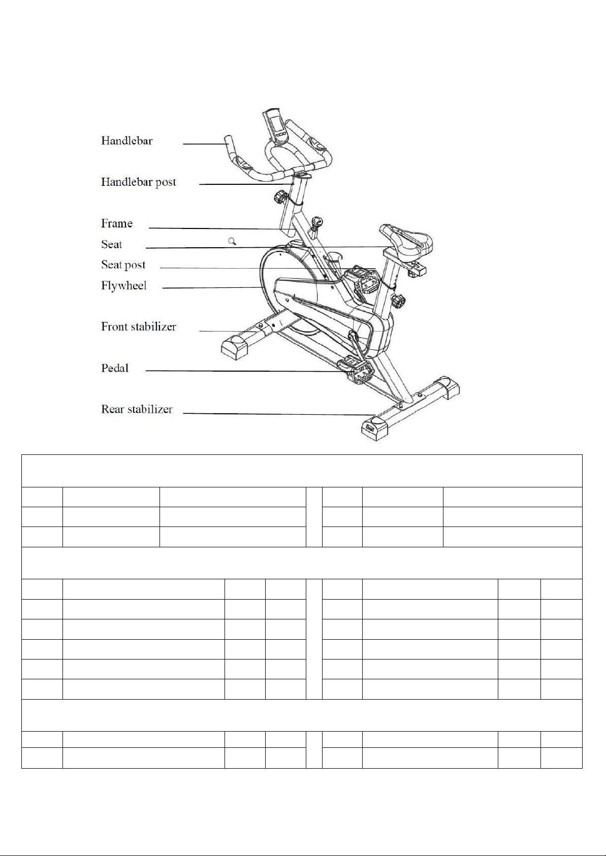
1.
Product Brief
Main Parameters
No.
Item
Description
No.
Item
Description
1
Max Load
140kg
3
Product Size
1060*530*1230mm
2
Flywheel
13kg
Packing List
No.
Item
Unit
Qty
No.
Item
Unit
Qty
1
Frame
pc
1
6
Handlebar Post
pc
1
2
Front Stabilizer
pc
1
7
Phone Holder
pc
2
3
Rear Stabilizer
pc
1
8
Front Handlebar
pc
1
4
Pedal
set
1
9
Seat Post
pc
1
5
Seat
pc
1
10
Toolkit
set
1
Toolkit List
No.
Item
Unit
Qty
No.
Item
Unit
Qty
1
Cap Nut
pc
4
4
Combination Wrench
pc
1
2
2
Flat Washer
pc
4
5
Allen Key
pc
1
3
Carriage bolt
Pc
4
5
6
Wrench pc
1

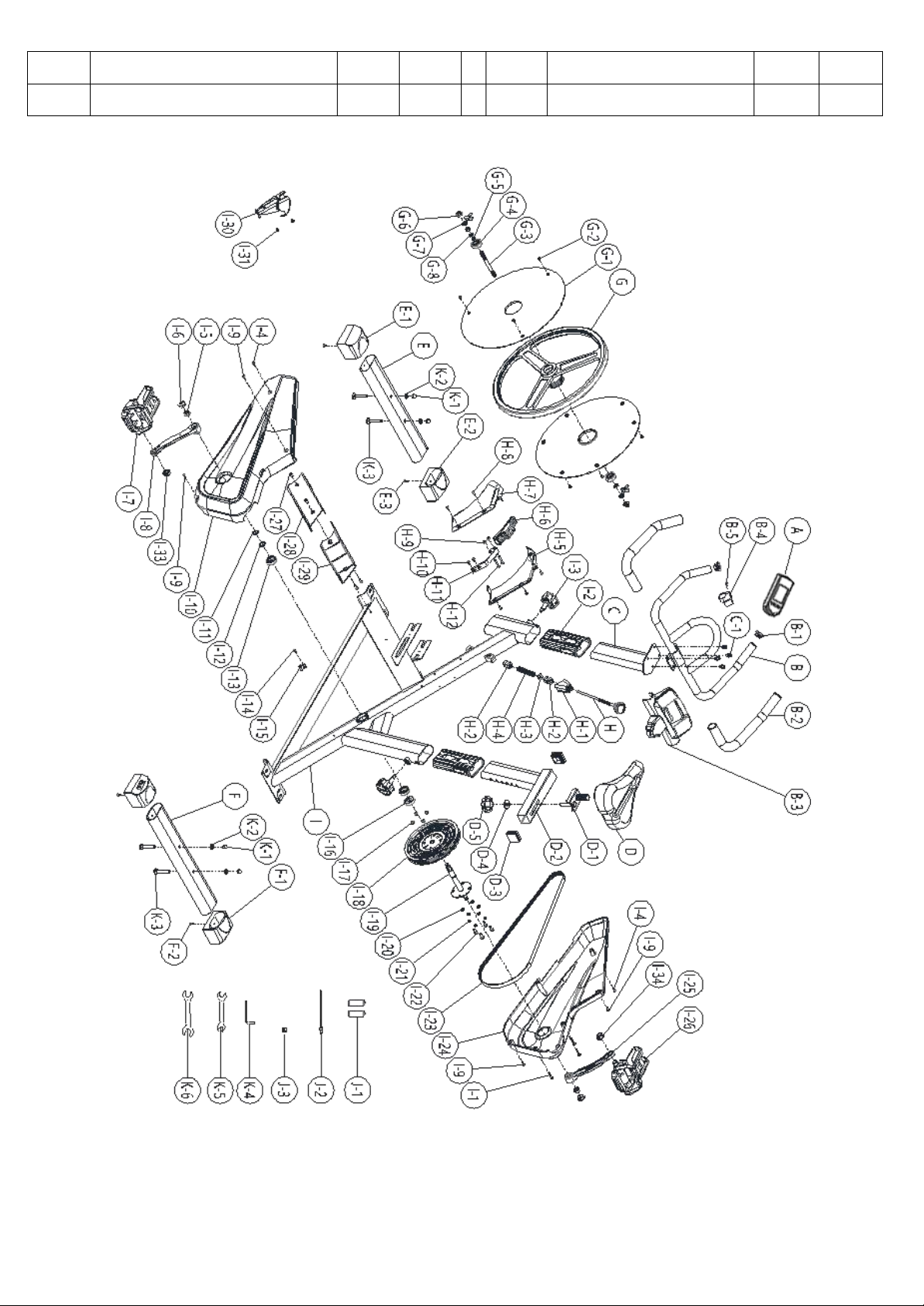
5
NO.
ITEM
QTY
NO.
ITEM
QTY
A
Monitor
1
H-5
Dust cap(right)
1
B
Front handlebar
1
H-6
Brake assembly
1
B-1
Tube plug
2
H-7
Dust cap(left)
1
B-2
Handlebar cover
2
H-8
Cross flat head self tapping screw
5
B-3
Phone holder
1
H-9
Lock nut
2
B-4
Monitor frame
1
H-10
Cross flat head self tapping screw
2
B-5
Cross flat head screw
1
H-11
Brake pad
1
C
Handlebar post
1
H-12
Cross flat head screw
2
C-1
Hexagon socket Head Cap
Screw
4
I
Frame
1
D
Saddle
1
I-1
Cross flat head screw
3
D-1
Slider
1
I-2
Handlebar post sleeve
2
D-2
Seat post
1
I-3
Pull pin knob
2
D-3
Tube plug
2
I-4
Cross recessed pan head self tapping
self drilling screws
2
D-4
Flat washer
1
I-5
Hexagon Flange Nut
2
D-5
Seat adjusting knob
1
I-6
Crank plug
2
E
Front Stabilizer
1
I-7
Left pedal
1
E-1
Tube plug with moving
wheel(left)
1
I-8
Crank arm(left)
1
E-2
Tube plug with moving
wheel(Right)
1
I-9
Cross flat head self tapping screw
4
E-3
Cross flat head screw
2
I-10
Left cover
1
F
Rear stabilizer
1
I-11
Limit stopper
1
F-1
Tube plug with level adj. gear
2
I-12
Wavy washer
1
F-2
Cross flat head screw
2
I-13
Bearing
2
G
Flywheel
1
I-14
Cross flat head self tapping screw
1
G-1
Flywheel cover
2
I-15
Sensor bracket
1
G-2
Cross Recessed Pan Head
Tapping Screw
6
I-16
Axle sleeve for Crank Shaft
1
G-3
Flywheel axis
1
I-17
Lock nut
4
G-4
Bearing
2
I-18
Pulley
1
G-5
Flat washer
1
I-19
Crank shaft
1
G-6
Hexagon Flange Nut
2
I-20
Flat washer
4
G-7
Belt tensioner
2
I-21
Spring washer
4
G-8
Hex nut
3
I-22
Outer hexagon bolt
4
H
Brake lever
1
I-23
Belt
1
H-1
Decorative cover(upper)
1
I-24
Right cover
1
H-2
Brake sleeve(lower)
2
I-25
Crank arm(right)
1
H-3
Square brake nut
1
I-26
Pedal(Right)
1

6
H-4
Brake spring
1
J-2
Sensor box
1
I-28
Left cover of supporting plate
1
I-27
Cross pan head screw
4
I-29
Right cover of supporting plate
1
J-3
Wire plug
1
I-30
Bottle bracket
1
K-1
Cap nut
4
I-31
Cross pan head tapping screw
2
K-2
Flat washer
4
K-3
Carriage bolt
4
I-33
Nut(Left pedal)
1
K-4
Allen key
1
I-34
Nut(Right pedal)
1
K-5
Combination wrench
1
J-1
Battery(not provided)
2
K-6
Wrench
1
2. Safety Instructions and Warnings
To make sure your safety and avoid injuries, Please read the following instructions
carefully before using the bike and also pay attention to the following safety warnings.
NOTE:Though the product has been thoroughly considered in terms of safety issues in its design
and production, please make sure to follow the instructions below. We do not bear any
consequences caused by improper operation.
This bike is suitable for indoor use. Set up and operate it on a solid level surface. Do not place
any objects on the bike.
If the power cord is damaged, to avoid danger, it must be replaced by professionals from the
manufacturer, its maintenance department or related departments. If not in use for a long time,
please unplug the power cord.
This products is of H level. When the product is not in use, please lock the flywheel to avoid
injury.
This product is not suitable for the disables and children. Please do not use it if you feel unwell,
otherwise it may cause injury.
Do not use the bike in a dusty room and maintain it a certain humidity. Avoid strong static
electricity or it will affect the normal use of the console. Please use the original parts, they are
forbidden to be replaced without instructions.
Do not use the bike near a hot or moving object.
Please unplug the bike before moving it. Non-professionals are not allowed to disassemble the
bike without authorization, otherwise serious consequences may occur.

5
2.
Safety Instructions and Warnings
To make sure of your safety and avoid injuries, Please read the following instructions
carefully before using the bike and also pay attention to the following safety warnings.
NOTE:Though the product has been thoroughly considered in terms of safety issues in its
design and production, please make sure to follow the instructions below.
We do not bear any consequences caused by improper use.
◆
This bike is suitable for indoor use. Set up and operate it on a solid level surface. Do not place
any objects on the bike.
◆
If the power cord is damaged, to avoid danger, it must be replaced by professionals from the
manufacturer, its maintenance department or related departments.
◆
Please unplug the power plug if the product is not used for long time.
◆
When the product is not in use, please lock the flywheel to avoid injury.
◆
This product is not suitable for children. Please do not use it if you feel unwell, otherwise it may
cause injury.
◆
Handicapped or disabled persons should not use the spinning bike without the advice of a
qualified health professional or physician.
◆
Do not use the bike in a dusty room and maintain it the room to a certain humidity. Avoid strong
static electricity or it will affect the normal use of the console. Please use the original parts,
they are forbidden to be replaced without instructions.
◆
Do not use the bike near a hot or moving object.
◆
Please unplug the bike before moving it. Non-professionals are not allowed to disassemble the
bike without authorization, otherwise serious consequences may occur.
◆
Please make sure the garment is fastened or zippered, do not wear loose or dangling clothing
while using the bike.

6
◆
If you feel unwell or uncomfortable during use, please stop and consult a physician.
◆
Use qualified sockets to avoid danger. If the plug is not compatible with the socket, please do
not touch the plug and ask an electrician to handle it.
◆
The product is suitable for home use, not for professional training and test, can not be used for
medical purposes.
◆
Do not use it when the shell is cracked, broken off (the internal structure is exposed) or the
welded part is cracked.
◆
Do not use immediately after eating, feeling fatigue, or not in a good physical condition.
--It may do harm to your health.
◆
Do not scatter objects like needles, trash or water on the plug. Do not touch the plug with
wet hands.
--It may cause electric shock, short circuit, or fire.
◆
Please unplug the bike when not in use.
H A R D WA R E I D E N T I F I C AT I O N C H A
R T
- - - - - - - - - - - - - - - - - - - - - - - - - - - - - - - - - - - - - - - - - - - - - - - - - - - - - - - - - - - - - - - - - - - - - - - - - - - - - - - - - - - - - -
This chart is provided to help identify the hardware used in the assembly process. Use the small
scale to check the length of the bolts and screws.
7
3.
Installation Instructions
As you assemble it, all screws are simply attached first, and finally tightened after
the bike is completely assembled.
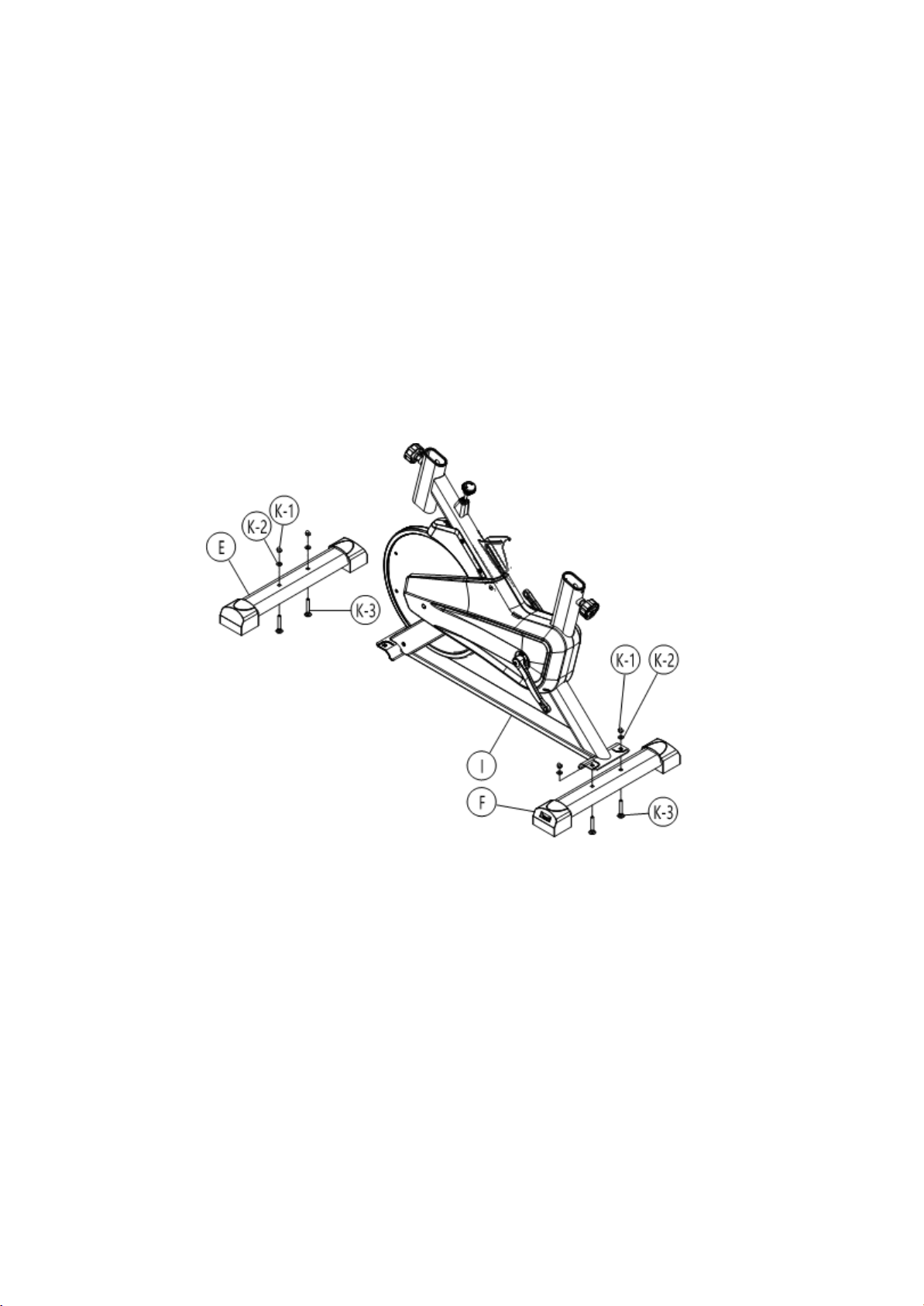
Step 1. Take out the bike frame I#, Front Stabilizer E#, and the Rear Stabilizer F# from the package.
Take out the combination wrench K-5# , cap nut K-1#, flat washer K-2#, and carriage bolt K-3. Install
as shown in the figure below: Place the stabilizers and the frame as shown below. Align the holes on
stabilizers with the ones on the frame, and place the fasteners with the order of carriage bolt K-3#, flat
washer K-2 and cap nut K-1# and finally use the combination wrench K-5 to secure it.

8
Step 2. Take out the Right Pedal I-26#, Nut I-34#, Left Pedal I-7# and Nut I-33# from the package.
Install as shown in the figure below: use the Combination Wrench K-5# to rotate in the arrow
direction and then use wrench K-6# to secure.
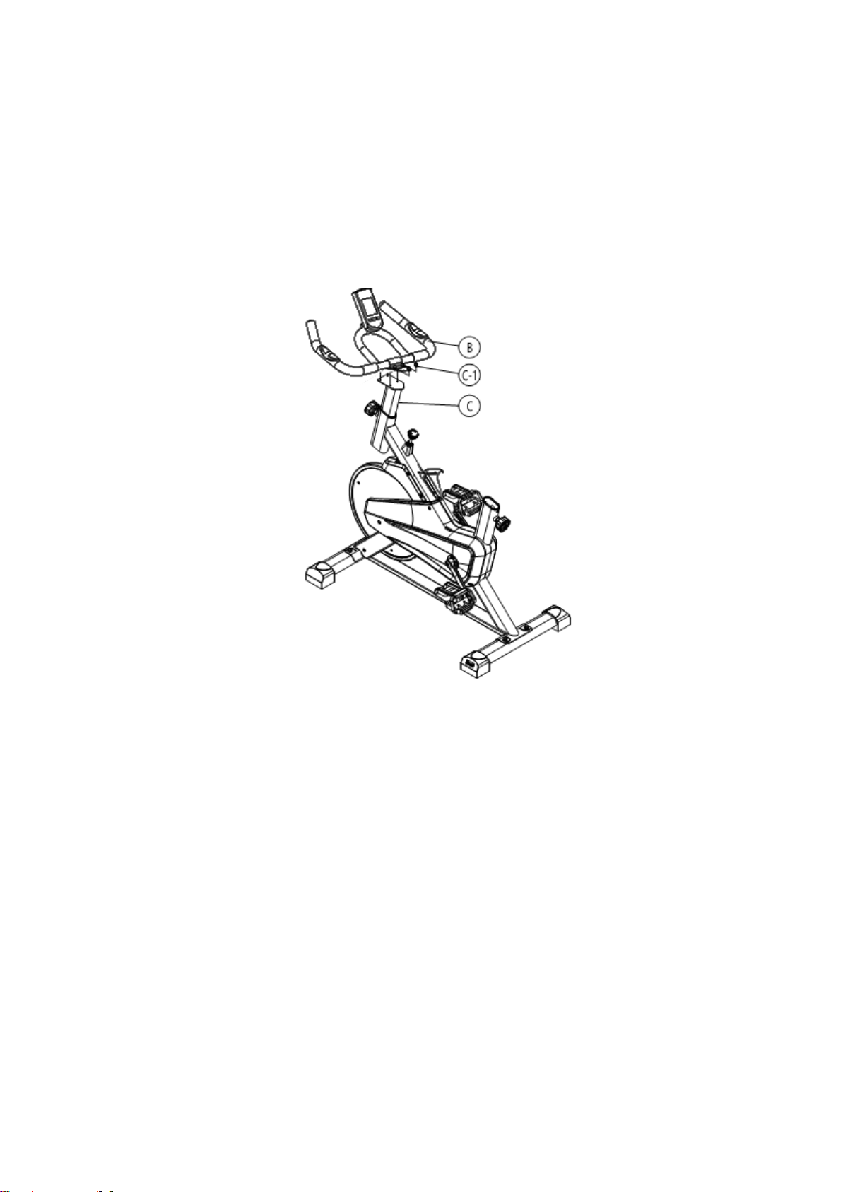
Step 3. Take out the Handlebar Post C#. Loose the Pull pin knob I-3#, and insert the
handlebar post C# into the frame I#. Adjust the height of the handlebar post according
to user’s height and use the pull pin knob I-3# to lock it.
9
Step 4. Take out the Front Handlebar B# and install as shown in the figure below: Use Allen key K-
4# to remove the pre-assembled Hexagon socket head cap screw. Install the front handlebar B# and
align it with the handlebar post C# and use the Allen key K-4 and screw C-1 to secureit.
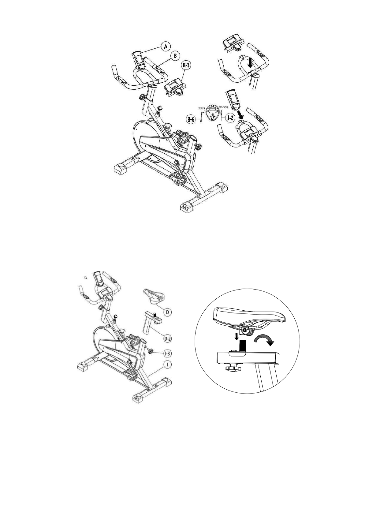
Step 5. Take out the monitor A# and phone holder B-3#. Install as shown in the pictures below:
Buckle the phone holder B-3# and monitor A# onto the front handlebar B# with the arrow showing
direction below. Insert the communication wires into the sensor slots on the back of the monitor.Insert
the handle pulse wires B-6# into the PULSE slots on the back of the monitor.
10
Step 6. Take out the Saddle D# and Seat post D-2# from the package, install as shown in the figure
below: Put the seat post D-2# into the frame I#. Adjust the height of the saddle according to the user’s
height and use the pull pin knob I-3# to lock it. Install the Saddle D# onto the Seat post D-2,and use
the Combination Wrench K-5# to lock the seat after adjusting into a proper angle and direction.

11
Please do not lock all screws tightly until you have followed all steps above to
assemble the bike. Please inspect carefully before using the bike
You can adjust the height of handlebar and seat with the adjusting knob according to
your sitting posture.
Note: Please don't exceed the STOP mark when adjusting the height of the
handlebar post.
Seat Adjustment:
You can adjust the seat distance from the handlebar with the adjustment handle under
the seat.
Please press STOP brake knob hard if in the event of an emergency.
When the product is not in use, please keep the resistance in the
highest level by rotating the brake knob and loose it before using next
time.

12
4.
Warm-up Suggestions
Warm-up and Stretching
WARM-UP
The purpose of warming up is to prepare your body for exercise and to minimize
injuries. Warming up for two to five minutes before strength training or aerobic
exercising can raise your heart rate and warm your working muscles which can also
help to avoid injuries.
STRETCHING
Stretching is very important to warm up your muscles before exercise to avoid injuries or to
relax your muscles to relieve the soreness in muscles after strength or aerobic training.
Muscles stretches are easier and more efficient at this time because of their elevated
temperature, which greatly reduces the risk of injury. Each stretch should be held for 15 to 30
seconds.
Here are the suggested warm-up and stretching exercise as below.

13
5.
Console Function Instruction
FUNCTION BUTTONS
MODE
a) Press the button to select TIME, DISTANCE, CAL and PULSE to preset.
SET
a)To set up the target value of TIME, DISTANCE, CAL and PULSE.b)
Hold down the button to speed up the increment.
RESET
a)Press the button to reset function value when setting .
b)Press the button and hold for 2 seconds to reset all value to be zero.
(When the user replace batteries, all the values will reset to ZERO automatically.)
FUNCTIONS & OPERATIONS
1.
Time
Accumulates total time from 00:00 up to 99:59.The user may preset target time by pressing SET
button .Each increment is 1 minute. Automatically count down from targeting value during
exercise.
2.
Speed
Display the current training speed from 0.0 to 999.9 KPH or MPH.
3.
Distance
Accumulates total distance from 0.0 up to 999.9 km or mile. The user may preset target distance
by pressing SET button. Automatically count down from targeting value during exercise.
4.
Calories
Accumulates calories consumption during training from 0 to max.999.9 calories. The user may
also preset the target calorie before training by press SET & MODEbutton.
Automatically count down from targeting value during exercise.
Note:
1)
If the computer displays abnormally, please re-install the battery and try again.
2)
The batteries must be removed from the appliance before it is scrapped and that they are
disposed of safely.
3)
While the user starts to do exercise, the Display will show out the workout value automatically.
Once they stop exercising over 256 sec. the Display will turn off.

14
6. Maintenance
CLEANING:
Thorough cleaning will extend the life of the spin bike.
Remove dust regularly to keep it clean. Make sure your sneakers are clean to avoid
carrying foreign objects into the spin bike.
MAINTENANCE:
Replace the defective parts immediately or do not use the product until the defective parts
are replaced. Please pay special attention to the most easily worn components.
This manual suits for next models
1
Table of contents
Other HIT FITNESS Exercise Bike manuals


Popular Exercise Bike manuals by other brands


Sunny Health & Fitness
Sunny Health & Fitness SF-B121021 user manual

Monark
Monark 827E instruction manual

Stamina
Stamina 1310 owner's manual

American Fitness
American Fitness SPR-BK1072A owner's manual
 Service manual")
Cateye
Cateye CS-1000 (CYCLO SIMULATOR) Service manual

BH FITNESS
BH FITNESS H9158H Instructions for assembly and use